Portwell WADE-8021, User Manual
The Portwell WADE-8021 is a high-quality, reliable product designed for optimal performance. Improve your user experience by downloading the free User Manual from manualshive.com. This comprehensive manual provides step-by-step instructions for set-up, troubleshooting, and maintenance of the WADE-8021, ensuring you get the most out of your device.
Share
Download


Reviews:
No comments
Related manuals for WADE-8021

AirPro DWL-A520
Brand: D-Link Pages: 8

AirPro DWL-A520
Brand: D-Link Pages: 63

T12
Brand: Gallagher Pages: 13

RCR-1
Brand: Raymarine Pages: 46

GeForce RTX 2070 GAMING Z 8G
Brand: MSI Pages: 47

N640GT series
Brand: MSI Pages: 1

DHI-ASR2101A
Brand: Dahua Pages: 24

U3CR01
Brand: V.TOP Pages: 9

35FCREADAL
Brand: StarTech.com Pages: 3

USB-SoundBox 7.1
Brand: Conrad Electronic Pages: 4

ANT-RDR
Brand: AMX Pages: 2

ARE i2-LF
Brand: AEG Pages: 39

ARE H9
Brand: AEG Pages: 36
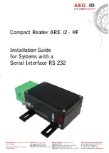
ARE i2 - HF
Brand: AEG Pages: 50
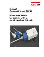
ARE I2
Brand: AEG Pages: 33

BCM94321CB2
Brand: Broadcom Pages: 16

CanProx One
Brand: Cansec Pages: 6

27730/20170302SZ019
Brand: CSL Pages: 40


