background image

www.polycom.com

© 2014, Polycom, Inc. All rights reserved. POLYCOM® and the names and marks associated with Polycom’s products are trademarks and/or service marks of

Polycom, Inc. and are registered and/or common law marks in the United States and various other countries. No portion hereof may be reproduced

or transmitted in any form or by any means, for any purpose other than the recipient’s personal use, without the express written permission of Polycom.

Polycom, Inc.

6001 America Center Drive

San Jose, CA 95002, USA

1725-08455-001/

D

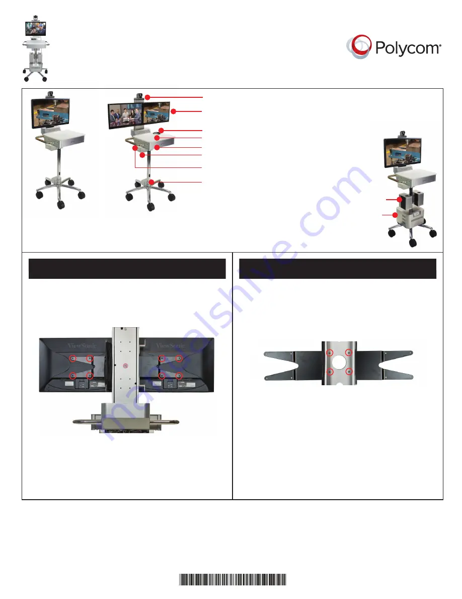
Setting Up the Polycom®
RealPresence® Utility Cart 500

Single 27” System

Dual 22” System

Base cart with laptop/accessory shelf

27” display or (2) 22” displays

Polycom EagleEye

TM

 IV camera

Storage drawer

AC and RJ45 jack

External 120V or 240V
power supply and
34Ah battery (lasts
approximately 4 hours)

Optional

Accessories

3” 2-way powered
monitor speaker system

Accessory basket

Microphone and 25’ cable

1  

Dual 22” Displays

Polycom RealPresence Group 500 system

Attach a 22” display on each side of the display bracket,
using four M4 x 10 Phillips pan head screws per display,
as shown circled in red below.

For a single 27” display, remove the dual display bracket
by opening the rear column cover and removing the
nuts holding the bracket, as shown circled in red below. 
Then, attach the 27” display, using four M4 x 10 Phillips
pan head screws.

Use this equipment only with the display(s) supplied
by Polycom. 

1  

Single 27” Display

Use this equipment only with the display(s) supplied
by Polycom. 

Summary of Contents for RealPresence Utility Cart 500

Page 1: ...f 27 display or 2 22 displays Polycom EagleEyeTM IV camera Storage drawer AC and RJ45 jack External 120V or 240V power supply and 34Ah battery lasts approximately 4 hours Optional Accessories 3 2 way powered monitor speaker system Accessory basket Microphone and 25 cable 1 Dual 22 Displays Polycom RealPresence Group 500 system Attach a 22 display on each side of the display bracket using four M4 x...

Page 2: ...clamp on each display using an M4 screw Connect the pre installed display cables and use the cable clamps to neatly fasten the cables behind the display Install the RealPresence Group 500 system power supply by removing the bottom plate Insert the power supply in the vertical position shown below then flip it to a horizontal position and reinstall the screw on the power supply bracket Connect the ...

Page 3: ...to the rear of the system Wrap the microphone cable on the cable hooks on one side of the display support column and neatly wrap the extra camera cable in the column 8 Optional Attach the utility shelf to either side of the drawer Open the drawer You may have to unlock it first Lift out the shelf Insert the shelf tabs into the side slots The shelf rests on the side handle The AC cable comes attach...

Page 4: ... Attach the power supply to the cart using the supplied screws Connect the RJ45 LAN cables from the power supply base to the LAN ports on the power supply Information is transmitted to LEDs on the power supply cover 10 Optional Battery Pack and Power Supply Module 11 Optional Battery Pack and Power Supply Module 12 Optional Battery Pack and Power Supply Module 13 Optional Battery Pack and Power Su...

Page 5: ...access for installing the cables down the pole Move the audio cable from the display down the pole Install the supplied AC power cable from the power strip and exit at the pole as shown below Pass the cables into the speaker assembly and attach the speaker assembly to the pole 15 Optional Battery Pack and Power Supply Module 16 Optional Powered Speaker Kit 17 Optional Powered Speaker Kit Take extr...

Page 6: ... Displays 1x Viewsonic 27 LED Display Model VS14818 Weight 10 9 lbs 4 9 kg or 2x Viewsonic 22 LED Display Model VA15451 Weight 6 9 lbs 3 1 kg each Ensure that the correctly rated battery option is fitted before connecting it to the mains supply CAUTION RISK OF EXPLOSION The battery can explode if it is replaced incorrectly or by an incorrect type Always observe correct polarity Only install batter...

Page 7: ...gs free from any obstructions The ambient operating temperature rating of this equipment is 0 40ºC and should not be exceeded Do not immerse the system in any liquid or place any liquids on it Do not spray liquids directly onto the system when cleaning Always apply the liquid first to a static free cloth For further information concerning the individual components of this equipment please refer to...

Page 8: ...rges depending on battery conditions environmental conditions and equipment load The Battery Charge LED Meter indicates the approximate charge level of the Battery Module see chart To power off connected equipment and the Power Supply Module s outlets and stop the battery from discharging press the Power button for one second The alarm will beep once briefly after one second has passed Release the...

Page 9: ...to automatic shutdown Stationary Operation Plugged in Charging Plug the system main power cord into a live AC wall outlet The system will deliver AC power to connected equipment while simultaneously charging the Battery Module Use connected equipment indefinitely as long as the Power Supply is connected to a live AC outlet If the utility power fails due to a blackout the system will automatically ...

Page 10: ...10 Setting up the Polycom RealPresence Utility Cart 500 Utility Cart 500 Wiring Diagram ...

Reviews: