


Pleiger Elektronik
GmbH & Co. KG
D-58456 Witten - Im Hammertal 51
D-58423 Witten - P.O.Box 32 63
Te49 (0) 23 24 * 3 98- 0
Telefax
+49 (0) 23 24
3 98- 3 89
www.pleiger-elektronik.de
[email protected]
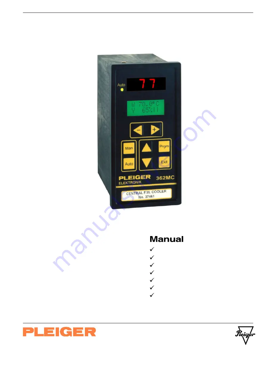
PLEIGER ELECTRONICS
362MC
Operation
Installation
Connection
Technical data
Hardware extensions
Functional extensions
Commissioning help
Edition: 6/2007
Subject to modifications


