Plankton Electronics ZAPS, Operation Manual
Introducing the Plankton Electronics ZAPS - a cutting-edge, compact electronic device engineered to revolutionize your audio experience. Unlock its full potential with our comprehensive Operation Manual, available for free download on our website. Explore endless possibilities and immerse yourself in the world of ZAPS, at your fingertips from manualshive.com.
Share
Download


Reviews:
No comments
Related manuals for ZAPS
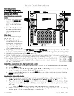
Bitbox
Brand: 1010 Music Pages: 2

SYSTEM 12
Brand: Moog Pages: 61

LIVEN 8bit warps
Brand: Sonicware Pages: 29

LIVEN BASS&BEATS
Brand: Sonicware Pages: 48

OB-X
Brand: Oberheim Pages: 25

K5000S
Brand: Kawai Pages: 132

DuoPoloy
Brand: CORNFIELD ELECTRONICS Pages: 24

Electribe ER-1 mkII
Brand: Korg Pages: 52

Mono Reverb black
Brand: Mosaic Pages: 6


