background image

Installation & Operation Manual

L20-294, rev. 0 (1/06)

IMPORTANT FOR FUTURE REFERENCE

Please complete this information and retain this manual
for the life of the equipment:

Model #: ___________________________
Serial #: ___________________________
Date Purchased: ____________________

ENGLISH

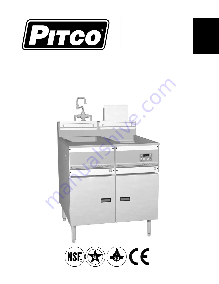
PG14D: Floor Model Gas Pasta Cooker
RS14D: Floor Model Rinse Station

Built after 4/1995

D

E

I

F

I

T

R

E

C

D

E S I G N


C

I

R

E

T

I

F

E D


Summary of Contents for PG14D

Page 1: ...rmation and retain this manual for the life of the equipment Model ___________________________ Serial ___________________________ Date Purchased ____________________ ENGLISH PG14D Floor Model Gas Pasta Cooker RS14D Floor Model Rinse Station Built after 4 1995 D E I F I T R E C D E S I G N C I R E T I F E D ...

Page 2: ...wer cord and it is damaged it must be replaced by a Pitco Authorized Service and Parts ASAP company technician or a similarly qualified person in order to avoid a hazard WARNING The power supply must be disconnected before servicing maintaining or cleaning this appliance WARNING The appliance is NOT jet stream approved DO NOT clean the appliance with a water jet WARNING DO NOT attempt to move this...

Page 3: ...UEL SUPPLY LINE LEAK AND PRESSURE TESTING 5 1 6 ELECTRICAL CONNECTIONS 6 1 7 VENTILATION AND FIRE SAFETY SYSTEMS 7 1 8 INSPECTION 8 1 9 INITIAL ADJUSTMENTS 9 1 9 1 FILLING THE APPLIANCE 9 1 9 2 LIGHTING INSTRUCTIONS 9 1 9 3 PILOT FLAME ADJUSTMENT 10 1 9 4 MAIN BURNER SYSTEM ADJUSTMENT 11 1 10 INITIAL CLEANING 13 2 OPERATION 14 2 1 OPERATIONAL FEATURES 14 2 2 FILLING THE APPLIANCE 16 2 2 1 FILLING ...

Page 4: ...E COOK TANK RINSE TANK IF EQUIPPED 19 3 1 3 CLEANING THE CABINET 19 3 2 MONTHLY PREVENTATIVE MAINTENANCE 20 3 2 1 DELIMING 20 3 3 ANNUAL PERIODIC PREVENTATIVE MAINTENANCE AND INSPECTION 20 3 3 1 TEMPERATURE PROBE HIGH LIMIT PROBE 20 3 3 2 CONTROLLER 20 3 3 3 CONTROL BOX ELECTRICAL COMPONENTS 20 3 3 4 TANK 21 3 3 5 DRAIN SYSTEM 21 3 3 6 GAS COMBUSTION SYSTEM 21 3 4 VENTILATION HOOD 21 4 TROUBLESHOO...

Page 5: ... for 15 days after delivery Check the packing list enclosed with your appliance to ensure that you have received all the parts to the appliance If you are missing any parts contact the dealer from whom the appliance was purchased As you unpack the appliance and its accessories be careful to keep the weight of the appliance evenly distributed Refer to the table below to identify which accessories s...

Page 6: ...his appliance The appliance s front panel tank splash back tank cover workshelf drain board is not a step Serious injury could result from slipping falling or contact with hot liquids WARNING DO NOT install this appliance next to a deep fat fryer A splash over of water into the hot oil may cause a flash fire WARNING DO NOT obstruct the flow of ventilation or air openings around the appliance Adequ...

Page 7: ...tside of the appliance with cardboard or a drop cloth when laying it down 2 Attach each leg caster with the hex head screws and nuts supplied Each leg caster requires four 20 x 5 8 hex head screws and nuts Insure that all screws are tight 3 Mount the screws from the inside of the appliance with the nut on the outside bottom of the appliance The nuts have lock washers attached to them therefore it ...

Page 8: ...e of a properly maintained water softener The incoming water pressure should be between 20 psi 1 38 bars to 60 psi 4 14 bars For higher water pressures a high pressure regulator must be installed to inlet plumbing to avoid damage caused by water hammer The maximum allowable incoming water temperature is 180 F 82 C Have your water tested and record the measured values below 1 4 2 DRAIN CONNECTIONS ...

Page 9: ...ors that comply with the Standard for Movable Gas Appliances ANSI Z21 69 CSA 6 16 latest edition This connection should include a quick disconnect device that complies with the Standard for Quick Disconnect Devices for Use With Gas Fuel ANSI Z21 41 CSA 6 9 latest edition When installing a quick disconnect you must also install adequate means for limiting the movement of the appliance without depen...

Page 10: ... codes and regulations WARNING The appliance must be grounded in accordance with local code if there is no local code comply with the NEC and ANSI NFPA No 70 latest edition for US and Canadian installations In all other cases refer to local and national codes and regulations To comply with European requirements European models are equipped with an equalization bonding clamp An equalization bonding...

Page 11: ...l emissions Excessive or unbalanced ventilation may cause drafts which could interfere with proper operation of the pilot and burners Leave at least 18 inches 45 72cm of open space between the flue of the appliance and the intake of the exhaust hood WARNING If your appliance is uses line current it is equipped with an oil proof electrical supply cord with a three prong safety plug This is to prote...

Page 12: ... is in its permanent location check the levelness Any additional leveling that is necessary can be performed as previously described 9 Ensure that the probe and high temperature limit is in place and secure Check the high limit bulb mounting screws to ensure that they are tight 9 Review the installation portion of this manual and ensure that all steps have been followed and executed properly ...

Page 13: ...n the knob Hold the knob in for approximately one minute to purge the air out of the line Hold a flame to the pilot until the pilot ignites this may take a little while the first time you light the pilot because of the air in the lines Once lit hold the knob in for approximately one minute and then release 4 If the pilot goes out wait 5 minutes and repeat step C If after three tries the pilot will...

Page 14: ...high limit wire terminal On particular systems pierce the high limit wire insulation with the tip of the test lead probe at the gas valve safety magnet connection 3 Connect the negative test probe to the pilot tubing 4 Remove the cap screw located below the pilot tubing on the gas valve The pilot flame adjustment screw is recessed behind this Turning the pilot flame adjustment screw clockwise lowe...

Page 15: ...supply line and light their main burners The pressure reading of the installed pressure gauge should not drop from the required installation pressure Any loss of pressure indicates inadequate supply line installation which will cause poor performance of all appliances during peak usage 3 The installed pressure gauge should be the same 0 1 W C 25mbar 02kPa as that marked on the data plate on the in...

Page 16: ...ermine the ideal flame profile 9 When the main burner flames have been properly adjusted lock the air collars in place by tightening the set screws A INSUFFICIENT FLOW The flame impinges on the tank front Tubes and baffles are carbonized Check vent and adjust if necessary Check heat tube and flue for blockage B EXCESSIVE FLOW The flame seems to lift off the burner face To correct adjust main burne...

Page 17: ...manual prior to filling or operating the appliance 2 The following steps should be followed using a grease dissolving commercial cleaner 3 Following the manufacturer s directions clean the tank interior and all other food contact surfaces 4 When cleaning is complete rinse the inside of the tank thoroughly with cool water Continue to rinse the tank until the cleaner has been completely and thorough...

Page 18: ...pped the appliance will stop heating if the drain valve is opened 5 Drain Outlet Water exits the cook tank through the drain outlet when draining or overflowing 6 Overflow Line When the cook tank water level reaches the overflow water will flow unobstructed through the overflow line and eventually exit the appliance through the drain outlet 7 High Temperature Reset Button This button may need to b...

Page 19: ...PG14D Floor Model Gas Pasta Cooker OPERATION 15 ...

Page 20: ...inse tank does not have level lines fill the tank so that the water is 4 inches 10 16cm below the overflow The tank can be filled up beyond the desired level but water may be lost through the overflow once pasta is placed into the tank 2 3 APPLIANCE START UP Refer to the following procedure to start the appliance prior to operation 1 Ensure that the drain valve is closed 2 Fill the cook tank with ...

Page 21: ...s with electric thermostat Press the boil simmer switch to the boil position All other Models Press the button until is displayed 2 4 3 TIMER OPERATION Not all control types include timers Timers provide accurate cook times for multiple product quantities and types Refer to the operator s manual for your appliance s specific control type to determine how to set the cook timers if equipped To start...

Page 22: ...2 tsp of oil per pound cooked is typical 2 5 APPLIANCE SHUTDOWN There are two shutdown modes of appliance operation STANBY and COMPLETE The standby mode removes the ability of the appliances main burners to operate Complete shutdown turns off the gas supply to the appliance Refer to the following procedures to enter the appropriate shutdown mode 2 5 1 STANDBY MODE 1 If the appliance is equipped wi...

Page 23: ...ank basket hanger baskets and temperature probe using a Scotchbrite or other abrasive pad with a commercial type cleaner specifically designed for cleaning and sanitizing food contact surfaces Follow the directions and familiarize yourself with the safe use of this cleaner prior to using it to clean the appliance Care must be taken to remove all the foreign material on the tank and on components i...

Page 24: ...rized Service Technician recommended by Pitco It may be necessary perform this inspection more then once a year 3 3 1 TEMPERATURE PROBE HIGH LIMIT PROBE 9 Verify probes are in good working condition Check for damage and that the fasteners are tightly secured to the tank 9 Verify compression fittings are leak free 9 Check wiring for loose electrical connections 3 3 2 CONTROLLER Perform the followin...

Page 25: ... leaks 9 Check and clean vent tube on gas valve pressure regulator 9 Check burners clean debris and grease from pilot and pilot orifice tips 9 Check and adjust burner manifold gas pressure to nameplate reading 9 Check incoming gas pressure when all gas appliances are on 9 Check ignition system and adjust pilot flame as required 9 Check flame sensor reading 9 Recheck for gas leaks after inspection ...

Page 26: ... procedure to reset the switch 1 Turn the appliance off 2 Allow the appliance ample time to cool to room temperature 3 Add water to the cook tank as needed 4 Press the high temperature reset button if equipped 5 The high limit switch is now reset and the appliance is ready for start up 4 3 DRAIN VALVE INTERLOCK If your appliance is equipped with a drain valve interlock circuit the appliance will s...

Page 27: ... on controller Controller does not activate Power Cord loose or not connected Connect power cord Controller displays that it is heating but water will not heat High temperature limit has tripped Allow appliance to cool and reset High temperature limit Display Problem Action Water temperature is low Wait for appliance to heat up Incorrect probe reading Contact Authorized Service Company Water level...

Page 28: ... 225 6684 World Wide Website Address www pitco com In the event of problems with or questions about your equipment please contact the Pitco Frialator Authorized Service and Parts representative ASAP covering your area or contact Pitco at the numbers listed to the left MAILING ADDRESS P O BOX 501 CONCORD NH 03302 0501 SHIPPING ADDRESS 10 FERRY ST CONCORD NH 03301 ...

Reviews: