ORDER NO.
PIONEER CORPORATION
4-1, Meguro 1-chome, Meguro-ku, Tokyo 153-8654, Japan
PIONEER ELECTRONICS (USA) INC.
P.O. Box 1760, Long Beach, CA 90801-1760, U.S.A.
PIONEER EUROPE NV
Haven 1087, Keetberglaan 1, 9120 Melsele, Belgium
PIONEER ELECTRONICS ASIACENTRE PTE. LTD.
253 Alexandra Road, #04-01, Singapore 159936
PIONEER CORPORATION
2008
2008 Printed in Japan
EJECT
POWER
STOP
STOP
REAR
DISC
1
USB
1
USB
2
DISC
2
EJECT
MEP-7000
MULTI ENTERTAINMENT PLAYER
TRACK SEARCH
CUE/LOOP
EJECT
TIME
A.CUE
IN/CUE
HOT LOOP
LOOP
RELOOP/EXIT
PITCH BEND
BROWSE
MIX
EFFECT
UTILITY
MT
0
MASTER
TEMPO
TEMPO
6/10/16WIDE
OUT/ADJUST
FWD
TEMPO
REV
MEMORY
CALL
SEARCH
QUE
JO
G
B
R
E
A
K
SCR
ATC
H
TRACK SEARCH
CUE/LOOP
EJECT
TIME
A.CUE
IN/CUE
HOT LOOP
LOOP
RELOOP/EXIT
PITCH BEND
MT
0
MASTER
TEMPO
TEMPO
6/10/16WIDE
OUT/ADJUST
FWD
TEMPO
REV
MEMORY
CALL
SEARCH
QUE
JO
G
B
R
E
A
K
SCR
AT
CH
A
LOAD
B
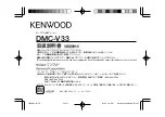
MEP-7000
LOAD
MULTI ENTERTAINMENT PLAYER
CO
N
TROL U
N
IT
DRIVE U
N
IT
MEP-7000
RRV3719
MULTI ENTERTAINMENT PLAYER
MEP-7000
THIS MANUAL IS APPLICABLE TO THE FOLLOWING MODEL(S) AND TYPE(S).
: This product comprises a control unit (CU-V170) and a drive unit. Note that
a user should bring in both units for servicing.
Model
Type
Power Requirement
Remarks.
MEP-7000
KUCXJ
AC 120
V
MEP-7000
WYXJ5
AC 220
V
to 240
V
MEP-7000
TLFXJ
AC 110
V
to 240
V
MEP-7000
WAXJ5
AC 220
V
to 240
V
For details, refer to "Important Check Points for good servicing".
T-ZZR JULY