background image

PIONEER CORPORATION

4-1, Meguro 1-Chome, Meguro-ku, Tokyo 153-8654, Japan 

PIONEER ELECTRONICS SERVICE INC.

P.O.Box 1760, Long Beach, CA 90801-1760 U.S.A.

PIONEER ELECTRONIC NV

Haven 1087 Keetberglaan 1, 9120 Melsele, Belgium 

PIONEER ELECTRONICS ASIACENTRE PTE.LTD.

253 Alexandra Road, #04-01, Singapore 159936

PIONEER CORPORATION 2001

K-ZZU. MAY 2001 Printed in Japan

ORDER NO.

CRT2671

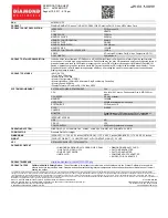
7 INCH WIDE AV SYSTEM DISPLAY

AVX-7300

UC

Service
Manual

CONTENTS

1. SAFETY INFORMATION............................................2

2. EXPLODED VIEWS AND PARTS LIST ......................2

3. BLOCK DIAGRAM AND SCHEMATIC DIAGRAM ..10

4. PCB CONNECTION DIAGRAM................................28

5. ELECTRICAL PARTS LIST........................................41

6. ADJUSTMENT .........................................................49

7. GENERAL INFORMATION.......................................49

7.1 DIAGNOSIS ........................................................49

7.1.1 TROUBLESHOOTING ..............................49

7.1.2 DISASSEMBLY .........................................53

7.1.3 CONNECTOR FUNCTION DESCRIPTION57

7.2 IC

..................................................................58

7.3 EXPLANATION ...................................................62

7.3.1 MECHANISM DESCRIPTIONS ................62

7.3.2 OPERATIONAL FLOW CHART.................66

8. OPERATIONS AND SPECIFICATIONS ....................67

AVX-7300

EW

AVX-7300

ES

NOTE:

-

Inverter for LCD back light becomes a high voltage. 

-

About FPC between control PCB and relay unit.

There is a direction of the connector and the installation is noted. 

Please note that the length of the line is short at the time of detaching. 

Summary of Contents for AVX-7300/ES

Page 1: ... EXPLODED VIEWS AND PARTS LIST 2 3 BLOCK DIAGRAM AND SCHEMATIC DIAGRAM 10 4 PCB CONNECTION DIAGRAM 28 5 ELECTRICAL PARTS LIST 41 6 ADJUSTMENT 49 7 GENERAL INFORMATION 49 7 1DIAGNOSIS 49 7 1 1 TROUBLESHOOTING 49 7 1 2 DISASSEMBLY 53 7 1 3 CONNECTOR FUNCTION DESCRIPTION57 7 2IC 58 7 3EXPLANATION 62 7 3 1 MECHANISM DESCRIPTIONS 62 7 3 2 OPERATIONAL FLOW CHART 66 8 OPERATIONS AND SPECIFICATIONS 67 AVX...

Page 2: ... repairs can adversely affect the safety and reliability of the product and may void the warranty If you are not qualified to perform the repair of this product properly and safely you should mot risk trying to do so and refer the repair to a qualified service technician WARNING This product contains lead in solder and certain electrical parts contain chemicals which are known to the state of Cali...

Page 3: ...1715 CRB1715 7 4 Owner s Manual Not used CRB1716 CRB1720 7 5 Owner s Manual Not used CRB1742 CRB1721 7 6 Owner s Manual Not used CRB1718 Not used 7 7 Owner s Manual Not used CRB1719 Not used 7 8 Installation Manual CRD3482 CRD3481 CRD3483 7 9 Card ARY1048 Not used Not used 7 10 Warranty Card Not used CRY1157 Not used 8 Carton CHG4405 CHG4407 CHG4406 9 Contain Box CHL4405 CHL4407 CHL4406 10 Screw M...

Page 4: ...4 AVX 7300 2 2 EXTERIOR 1 3 A E ...

Page 5: ... CNR1609 54 Screw BPZ20P060FMC 55 56 57 Cover CNS6570 58 Button CAC6992 59 Button CAC6993 60 Button CAC6997 61 Cushion CNM6270 62 64 65 Keyboard Unit See Contrast table 2 66 Button See Contrast table 2 67 Badge CAH1786 68 Connector CN1901 CKS4511 69 Spacer CNM7247 70 72 73 Button RGB CAC7004 74 Button V SRC CAC7010 75 Detach Grille Assy See Contrast table 2 76 77 78 IC IC1901 TSOP1840SB1 1 EXTERIO...

Page 6: ...6 AVX 7300 G 2 3 EXTERIOR 2 3 C F ...

Page 7: ...ive Motor CXB7612 34 Screw IMS20P030FMC 35 Screw JFZ20P020FZK 36 Screw JFZ20P040FZK 37 Screw JGZ20P020FMC 38 Washer YE20FUC 39 Screw M2x2 2 CBA1419 40 Screw M2x2 5 CBA1447 41 Screw M1 7x3 CBA1475 42 Screw M2x2 CBA1484 43 Screw M3x3 CBA1534 44 Washer CBF1064 45 Spring CBH2469 46 Spring CBH2470 47 Spring CBL1527 48 Spring CBL1534 49 Spring CBL1545 50 Cord Assy CDE6685 51 Shaft CLA4007 52 Chassis CNA...

Page 8: ...8 AVX 7300 B 2 4 EXTERIOR 3 3 D ...

Page 9: ...table 2 18 Keyboard Unit See Contrast table 2 19 Screw BPZ20P060FMC 20 Screw JFZ20P022FNI 21 Sheet CNM7593 22 Sheet CNM7594 2 CONTRAST TABLE AVX 7300 UC AVX 7300 EW and AVX 7300 ES are constructed the same except for the following Part No Mark No Description AVX 7300 UC AVX 7300 EW AVX 7300 ES 8 Grille Unit CXB7268 CXB7268 CXB7557 14 Cover CNS6628 CNS6628 CNS6564 16 Screw CBA1484 CBA1484 CBA1551 1...

Page 10: ...0 KEY1 KEY2 KEY0 KEY1 KEY2 5 RGB com 44 OSD 15 BEEP_M 45 VSYNC 61 LSENS 76 AVON 59 PBSENS 54 X1 70 X2 69 KEY3 80 X601 4 19MHz 29 CN101 CN1103 R 30 G 31 B 27 HSY 26 VSY HSY VSY DIM VSEL OSD VIDEO G R B 45 DIMMER 15 RGB COM 21 OSD 33 46 V SYNC 20 21 22 24 25 6 36 30 18 5 IC 605 TC74VHCT08AFT Q1101 C RELAY UNIT Q404 Q653 CN651 CN401 CN1901 3 RGLED B 10 11 REMIN 6 3 10 11 6 reset reset 60 IC 603 S 807...

Page 11: ...T Q2941 Q2942 IC 2941 OZ960IS 7 12 Q2943 20 Q2944 S2942 DOWN UP MENU S2944 S2943 T2941 CN2941 DIM 6 D INVERTER PCB LCD MODULE IC 1901 TSOP1840SB1 KEY MATRIX RESET ILM B S1902 GRILLE PCB CN1301 3 1 B PHOTO PCB IC 1301 NJM062V 7 OPEN CLOSE S1301 CN2804 6 3 2 1 2 5 F ENCODER PCB IC2807 TC7W14FU IC2806 GP1S25 7 1 2 4 IC2805 GP1S25 5 3 4 2 2 DRIVE SW S2801 R DEGPUL DEG0SW 1 2 1 2 IC2804 TC7S14FU 1 2 IC...

Page 12: ...TER SYNC SEPARATOR C CN1103 E CN1901 EW A 3 2 CONTROL PCB GUIDE PAGE Note When ordering service parts be sure to refer to EXPLODED VIEWS AND PARTS LIST or ELECTRICAL PARTS LIST A a A b A a A a A b A b A b A b A a A a Large size SCH diagram Guide page Detailed page A a ...

Page 13: ...e component parts indicates the importance of the safety factor of the part Therefore when replacing be sure to use parts of identical designation Symbol indicates a resistor No differentiation is made between chip resistors and discrete resistors NOTE Symbol indicates a capacitor No differentiation is made between chip capacitors and discrete capacitors A CONTROL PCB Control Unit Consists of Cont...

Page 14: ...14 AVX 7300 A 1 2 3 4 B C D 1 2 3 4 EW ES MONITOR MICRO COMPUTER SYNC SEPARATOR CN1103 A a A b A a 1 ...

Page 15: ...15 AVX 7300 5 6 7 8 A B C D 5 6 7 8 EW ES MONITOR MICRO COMPUTER C CN110 E CN1901 EW A a A b A a 2 3 ...

Page 16: ...16 AVX 7300 A 1 2 3 4 B C D 1 2 3 4 1K 1 2W A CONTROL PCB Control Unit Consists of Control PCB Photo PCB A a A b A b 1 ...

Page 17: ...R022 The mark found on some component parts indicates the importance of the safety factor of the part Therefore when replacing be sure to use parts of identical designation Symbol indicates a resistor No differentiation is made between chip resistors and discrete resistors NOTE Symbol indicates a capacitor No differentiation is made between chip capacitors and discrete capacitors A a A b A b 2 3 ...

Page 18: ...18 AVX 7300 A 1 2 3 4 B C D 1 2 3 4 OPEN CLOSE C CN1101 B PHOTO PCB Control Unit Consists of Control PCB Photo PCB B 3 3 PHOTO PCB ...

Page 19: ...19 AVX 7300 ...

Page 20: ...20 AVX 7300 A 1 2 3 4 B C D 1 2 3 4 L fixation always D CN2941 B CN1301 LCD MODULE F CN2804 C 3 5 RELAY UNIT H CN001 ...

Page 21: ...21 AVX 7300 5 6 7 8 A B C D 5 6 7 8 C RELAY UNIT A CN101 C ...

Page 22: ...22 AVX 7300 To CCFL C CN1101 D INVERTER PCB Keyboard Unit Consists of Inverter PCB Grille PCB D2951 1SS355 D2950 UDZ5R6 B A 1 2 3 4 B C D 1 2 3 4 3 6 INVERTER PCB D ...

Page 23: ...N651 E GRILLE PCB Keyboard Unit Consists of Inverter PCB Grille PCB EW model UC ES model EWmodel CSG1112 UC ES CSG1113 EW CSG1112 UC ES CSG1113 EW RGB V SRC Reset DETACH SENSE 1 2 3 4 A B C D 1 2 3 4 3 7 GRILLE PCB E ...

Page 24: ...24 AVX 7300 A 1 2 3 4 B C D 1 2 3 4 F M M1 Drive Motor CXB7612 Yellow Black Red White CN1102 ENCODER PCB Encoder Unit Consists of Encoder PCB SW PCB SW PCB C F G DEG0 G 3 4 ENCODER UNIT ...

Page 25: ...25 AVX 7300 ...

Page 26: ...26 AVX 7300 A 1 2 3 4 B C D 1 2 3 4 H C CN1101 3 8 VIDEO SCHEMATIC ...

Page 27: ...27 AVX 7300 5 6 7 8 A B C D 5 6 7 8 H H VIDEO SCHEMATIC ...

Page 28: ... PCB DIAGRAMS 1 The parts mounted on this PCB include all necessary parts for several destination For further information for respective destinations be sure to check with the schematic diagram 2 Viewpoint of PCB diagrams Capacitor Connector P C Board Chip Part SIDE A SIDE B A A IC Q C CN1103 FRONT ...

Page 29: ...29 AVX 7300 5 6 7 8 A B C D 5 6 7 8 SIDE A A E E CN1901 ...

Page 30: ...30 AVX 7300 A 1 2 3 4 B C D 1 2 3 4 A CONTROL PCB A AV BUS IP OUT IP IN OPT OUT SPEAKER ...

Page 31: ...31 AVX 7300 5 6 7 8 A B C D 5 6 7 8 SIDE B A IC Q FRONT RGB CORD ...

Page 32: ...32 AVX 7300 A 1 2 3 4 B C D 1 2 3 4 F CN2804 A CN101 IC Q B CN1301 H CN001 D CN2941 C 4 2 RELAY UNIT SIDE A RELAY UNIT C ...

Page 33: ...33 AVX 7300 1 2 3 4 A B C D 1 2 3 4 IC Q C SIDE B RELAY UNIT C ...

Page 34: ...34 AVX 7300 A 1 2 3 4 B C D 1 2 3 4 CCFL MENU UP DOWN C CN1101 D 4 3 INVERTER PCB INVERTER PCB D INVERTER PCB D SIDE A SIDE B ...

Page 35: ...35 AVX 7300 1 2 3 4 A B C D 1 2 3 4 IC Q IC1901 Q1901 RGB V SRC RESET DETACH SENSE IC Q Q1902 Q1903 Q1904 A CN651 E 4 4 GRILLE PCB GRILLE PCB SIDE A SIDE B E GRILLE PCB E ...

Page 36: ...36 AVX 7300 A 1 2 3 4 B C D 1 2 3 4 G CN1102 C M1 F 4 5 ENCODER PCB ENCODER PCB F SIDE A SIDE B ENCODER PCB F ...

Page 37: ...37 AVX 7300 1 2 3 4 A B C D 1 2 3 4 DEG0 F CN2806 4 6 SW PCB G SIDE A SIDE B SW PCB G SW PCB G ...

Page 38: ...38 AVX 7300 A 1 2 3 4 B C D 1 2 3 4 4 7 VIDEO SCHEMATIC H VIDEO SCHEMATIC H C CN1101 ...

Page 39: ...39 AVX 7300 5 6 7 8 A B C D 5 6 7 8 H ...

Page 40: ...40 AVX 7300 A 1 2 3 4 B C D 1 2 3 4 4 8 PHOTO PCB IC Q C CN1101 OPEN CLOSE B PHOTO PCB B SIDE A SIDE B PHOTO PCB B ...

Page 41: ... CTF1379 L 403 Inductor CTF1379 L 404 Inductor CTF1379 L 405 Inductor CTF1379 L 406 Inductor CTF1379 L 601 Inductor CTF1379 L 602 Inductor CTF1379 L 603 Inductor CTF1379 L 604 Inductor CTF1379 L 605 Inductor CTF1379 L 606 Inductor CTF1379 L 607 Inductor CTF1420 Unit Number CWM7742 UC CWM7741 EW CWM7743 ES Unit Name Control Unit MISCELLANEOUS IC 101 IC NJM2903V IC 103 IC TC74VHCT08AFT IC 301 IC TC7...

Page 42: ...102J R 44 RS1 16S333J R 45 RS1 16S104J R 57 RS1 16S153J R 58 RS1 16S473J R 62 RS1 16S681J R 64 RS1 16S0R0J R 101 RS1 16S102J R 102 RS1 16S102J R 103 RAB4C102J R 104 RAB4C102J R 105 RAB4C102J R 106 RAB4C102J R 107 RS1 16S102J R 108 RAB4C221J R 109 RS1 16S101J R 110 RS1 16S102J R 111 RS1 16S101J R 112 RS1 16S103J R 113 RS1 16S103J R 114 RS1 16S392J R 115 RS1 16S912J R 116 RS1 16S2003F R 117 RS1 16S1...

Page 43: ...K50 C 43 CKSRYB472K50 C 44 CKSRYB472K50 C 45 CEV101M16 C 52 680µF 16V CCH1415 C 101 CKSRYB102K50 C 102 CKSRYB102K50 C 103 CEV101M16 C 104 CEV470M6R3 C 105 CKSRYB102K50 C 106 CEV4R7M25 C 107 CEV470M16 C 108 CKSRYB102K50 C 109 CEV101M16 C 110 CEV101M16 C 111 CEV101M16 C 112 CEV101M16 C 114 CKSRYB102K50 C 115 CKSRYB105K6R3 C 116 CSZS330M6R3 C 117 CFHSQ562J16 C 118 CKSRYB102K50 C 119 CKSRYB103K50 C 12...

Page 44: ...392J R 1122 RS1 16S392J R 1123 RS1 16S473J R 1124 RS1 16S105J R 1125 RS1 16S102J R 1126 RS1 16S512J R 1127 RS1 16S152J R 1128 RS1 16S0R0J R 1129 RS1 16S0R0J R 1130 RS1 16S222J R 1134 RS1 16S151J R 1135 RS1 16S0R0J CAPACITORS C 1101 CKSRYB104K16 C 1102 CEV470M16 C 1103 CEV470M16 C 1104 CSZSR101M6R3 C 1107 CSZSR101M6R3 C 1108 CKSRYB103K50 C 1109 CKSYB106K6R3 C 1112 CSZSR101M6R3 C 1114 CEV101M16 C 11...

Page 45: ...2944 RS1 16S473J R 2945 RS1 16S102J R 2946 RS1 16S513J R 2947 RS1 16S105J R 2948 RN1 16SE6802D R 2949 RS1 16S103J R 2951 RS1 16S103J R 2953 RS1 16S471J R 2955 RS1 16S393J R 2958 RS1 10S122J R 2966 RS1 16S153J CAPACITORS C 1901 CKSRYB104K16 C 1902 CKSRYB105K6R3 C 2941 CKSRYB104K16 C 2942 CKSRYB105K6R3 C 2943 CKSRYB103K50 C 2944 CKSRYB105K6R3 C 2945 CKSRYB474K10 C 2946 CKSRYB105K6R3 C 2947 CKSRYB104...

Page 46: ...4 Q 205 Transistor 2SA1162 Q 206 Q 207 IC TC7S66FU Q 208 IC TC7S66FU Q 210 Q 211 IC TC7S66FU Q 212 IC TC7S66FU Q 271 IC TC74HC4053AFT Q 272 Transistor 2SA1162 Q 282 IC TC7W14FU Q 291 IC TC7SET08FU Q 292 IC TC7S14FU Q 293 IC TC7S14FU Q 501 IC TA75072F Q 502 Transistor 2SC3265 Q 503 Transistor 2SA1298 Q 504 Transistor 2SC3265 Q 505 Transistor 2SA1298 Q 651 IC AN6308S Q 652 Transistor 2SC2712 Q 801 Q...

Page 47: ...S101J R 234 RS1 16S102J R 235 RS1 8S680J R 236 RS1 8S680J R 237 RS1 8S680J R 238 RS1 16S681J R 239 RS1 16S561J R 240 RS1 16S1802F R 242 RS1 16S624J R 243 RS1 16S274J R 244 RS1 16S334J R 245 RS1 16S563J R 246 RS1 16S101J R 247 RS1 16S151J R 248 R 249 R 250 R 251 RS1 16S474J R 260 RS1 16S102J R 261 RS1 16S103J R 262 RS1 16S101J R 272 RS1 16S152J R 273 RS1 16S681J R 274 RS1 16S183J R 275 RS1 16S221J ...

Page 48: ...2 CSZSR47M20 C 223 CKSRYF105Z10 C 224 CSZS1R0M25 C 225 CKSRYB103K50 C 226 CKSRYB103K50 C 227 CKSRYB103K50 C 228 CKSRYB103K50 C 229 CKSRYB103K50 C 230 CKSRYB103K50 C 231 CCSRCH681J50 C 232 CCSRCH331J50 C 234 CSZSR68M16 C 235 CKSRYB103K50 C 236 CKSRYB154K10 C 237 CKSRYF104Z25 C 238 CSZSR68M16 C 239 CSZSR68M16 C 240 CKSRYF104Z25 C 241 CKSRYF104Z25 C 242 CKSRYF104Z25 C 243 CKSQYB474K25 C 246 CKSYB225K...

Page 49: ...ed at Pin 33 of Q201 IR3Y29BM 18 5V is obtained at JP851 12V is obtained at JP852 3 3V is obtained at JP853 5 3V is obtained at JP809 and 7 5V is obtained at JP808 Sync signal is obtained at Pin 36 of Q201 IR3Y29BM Check Pin 13 14 of Q003 Gate array and its periphery Check Pin 3 of Q201 C204 and its periphery Yes Yes Yes Yes Yes Yes Yes Yes No No No No No No No No Go to Item2 No power Go to Item2 ...

Page 50: ...s input RGB signal for LCD is obtained at Pin 26 to Pin 28 of CN003 Connector Normal signal is obtained at each terminal of CN003 Check CN003 and its periphery Check Q271 TC74HC4053AFS and its periphery Go to Item 3 Out of Sync Go to Item 3 Out of Sync Check CN001 R248 to R250 the input connecting flexible cable and its periphery Yes Yes Yes Yes Yes Yes Yes Yes No No No No No No No No Replace LCD ...

Page 51: ...d its periphery Check Q801 VR801 and their periphery Yes Yes Yes Yes Yes Yes 7 5V is obtained at TP03 Yes Check C801 Yes No No No No No No No No Check Q803 T801 and their periphery Check F801 input flexible cables and their periphery Check 18 5V line to remove short circuits CN003 R017 Q003 and their periphery Check 12V line to remove short circuits Q502 Q505 Q501 and their periphery Check 3 3V li...

Page 52: ...ck Q201 IR3Y29BM and replace it Yes Yes No No No No No Check Q282 Pin 9 of Q003 Gate array and their periphery Check Pin 3 of Q201 C204 and their periphery Check CN001 R248 to R250 input flexible cables and their periphery Check X202 Ceramic resonator Q207 Q212 and their periphery Check X201 Ceramic resonator Q208 Q211 and their periphery Video signal is obtained at Pin 3 of Q201 IR3Y29BM RGB sign...

Page 53: ... and left side are aligned properly 3 Please do not attempt to operate the drive mechanism when the grill is not attached as doing so can cause the guides A and B to be caught by the edge of the chassis resulting in damage to these parts 4 Please remember to reapply grease on applicable parts when servicing gears and related parts Gears GEM1013 Gear GGM1034 Rack and all boards 5 Please be careful ...

Page 54: ...ove the six screws and then remove the Case Removing the Bracket Fig 5 Remove the two screws and then remove the two Brackets Removing the Holder Fig 4 Remove the four screws and then remove the Holder Fig 4 Fig 5 Case Holder Bracket Bracket ...

Page 55: ...hen remove the Grille Assy Removing the Control PCB Fig 6 Straight the tabs at six locations indicated Remove the screw Disconnect the connector and then remove the Control PCB Fig 6 Grille Assy Removing the Frame Fig 7 Remove the eight screws and then remove the Frame Fig 7 Frame Control PCB ...

Page 56: ...rs Remove the gear Pull out the Display Assy Fig 8 Display Assy Removing the LCD Module Fig 9 Remove the three screws and then remove the Cover Remove the four screws Disconnect the connector and then remove the LCD Module Fig 9 Cover LCD Module Cover Cover Display assy becomes such a condition ...

Page 57: ... 15 16 1 B U 2 GND 3 ILM 4 NC 5 ACC 6 P B 7 NC 8 NC 9 NC 10 NC 11 V IN 12 V IN_G 13 NC 14 NC 15 NC 16 NC 1 ANR 2 ANG 3 ANB 4 GNDSIG 5 CSYNC 6 NC 7 NC 8 MOREM 9 PRH 10 PRV 11 ILM 12 DSENS 13 SP 14 ACONT 15 GNDA 16 SWACC5 17 PWRVI 18 PWRFL 19 SP 20 GNDFL 20 19 2 20 2 1 19 1 ...

Page 58: ... ac I Auto clear input 7 10 P6 P9 O Port output 11 VSS GND 12 P0 O Port output 13 P1 R O Port output or R output 14 P2 O Port output 15 P3 G O Port output or G output 16 P4 O Port output 17 P5 B O Port output or B output 18 HOR I Horizontal synchronous signal input 19 VERT I Vertical synchronous signal input 20 VDD Positive power supply terminal 1 10 11 20 PD5582A GP1S25 1 3 2 NC IN_A GND OUT_Y VC...

Page 59: ...SENSE1 I C Plus sense 1 32 DEG0SW I C Detection sense SW input of 0 in angle 33 VSS GND 34 pwsens I C Navigation R513 power ON input 35 pwsave O C Power save output 36 IPAUTO I N DVDSIP synchronization information 37 isens I N Illumination sensor input 38 dled O N Burglar alarm LED driving output 39 swvdd O N Remote controller power and external light sensing power outputs 40 BLTPW O C LCD backlig...

Page 60: ...unding circuit 72 XT2 Sub clock terminal 73 TESTIN I Test mode 74 AVDD I Analog power for A D converter 75 AVREF0 I Reference voltage input for A D converter 76 LSENS C External light sensor input 77 KEYIN1 C Key input 1 78 KEYIN2 C Key input 2 79 KEYIN3 C Key input 3 80 KEYIN4 C Key input 4 Format Meaning C C MOS N N channel open drain PE5230A 20 21 40 41 60 61 80 1 INPUT GND 1 2 3 OUTPUT REGULAT...

Page 61: ...B PDR_A ZVS Phase Shift Controller HF OSC PDR_C NDR_D Burst Mode Control OVP ENA hys COMP hys COMP 1 5V 2V Reference OPLAMP EA Ignition 1 25V 2V 2 50V sub POFF POFF I 3uA I 6uA Soft Start ACTIVE HIGH OZ960IS DECODER TSD 9 8 7 6 5 4 3 2 10 11 12 13 14 15 16 1 PREAMP CTL AMP GND VCTL RC PCT RIN VB M1 ATC CS AMP TL AMP M2 FIN Pc Vcc TL CS RT2 RT1 RM1 RM2 RM2 RM1 BA6951FS ...

Page 62: ... system is in the automatic ejection and retraction setting 6 The back and forth movements are set to a high speed mode and angular control is set to a low speed mode at all times switch is set by the hardware 7 Braking is continuous even after the motor has stopped 8 The brake is applied once when the motor switches from one operating mode to another 7 3 EXPLANATION 7 3 1 MECHANISM DESCRIPTION Ou...

Page 63: ...been stored in the memory however the motor will continue to operate until that angle has been attained 54 edges 100 degrees or the position stored in the memory Retraction Operation 1 The motor is driven in a low speed mode when the OPEN CLOSE key is pressed or after six seconds when an ACC OFF state is attained when the automatic ejection and retraction setting is set to ON 2 The motor is driven...

Page 64: ...l abnormality exists and the operation will be halted at that point 3 The brake operation is performed at 14ms 200ms time required for monitoring the chattering after the prescribed L angular pulses are detected Angular adjustments 1 When the UP key is pressed the monitor is raised from its initial position 100 degrees and will continue to rise until the key is released The operation will stop one...

Page 65: ...ward operation Reverse operation CLOSE Remaining in 6 sec CLOSE condition CLOSE Continued OPEN operation CLOSE Final position memory OPEN OPEN CLOSE CLOSE Mode setting Automatic ejection and retraction setting OFF ACC operation mode In OPEN condition During OPEN operation During CLOSE operation In CLOSE condition or when in or when in or when in or when in ACC OFF condition ACC OFF condition ACC O...

Page 66: ...66 AVX 7300 VDD 5V 68pin Power ON BSENS L ASENS L bsens 66pin asens 65pin DSENS L dsens 63pin SWVDD H 39pin Completes power on operation SYSPW H 55pin ADPOW L 6pin 7 3 2 OPERATIONAL FLOW CHART ...

Page 67: ...0 8 OPERATIONS AND SPECIFICATIONS 8 1 OPERATIONS Key Finder The following diagram shows the display when it is deployed Display V SOURCE button WIDE button RGB button RESET button OPEN CLOSE button ANGLE buttons ...

Page 68: ...le metal body Power supply side Ground side Connection method 2 Clamp firmly with needle nosed pliers Clamp the parking brake switch power supply side lead Note The position of the parking brake switch depends on the vehicle model For details consult the vehicle Owner s Manual or dealer This Product 1 Yellow To terminal always supplied with power regardless of ignition switch position Yellow video...

Page 69: ... 4 H 1 D in display 169 W 125 H 16 D mm 6 5 8 W 4 7 8 H 5 8 D in Weight 1 5 kg 3 3 lbs Display Screen size Aspect ratio 7 inch wide 16 9 effective display area 154 87 mm Pixels 336 960 1 440 234 Type TFT active matrix transmissive type Color system For U S and Canadian models NTSC Compatible Color system Other area models NTSC PAL Compatible Operating temperature range 20 to 60 C Storage temperatu...

Reviews: