pico Technology ADC-20, User Manual
The Pico Technology ADC-20 is a top-quality device that offers precise data acquisition capabilities. To make the most out of its features, it is crucial to consult the User Manual. You can effortlessly download the detailed manual for free from our website, ensuring seamless and optimal usage of your ADC-20.
Share
Download


Reviews:
No comments
Related manuals for ADC-20

iCAM M300
Brand: Gen2wave Pages: 44

PR1000IS Series
Brand: MadgeTech Pages: 4

OM-CP-OCTRTD
Brand: Omega Pages: 4
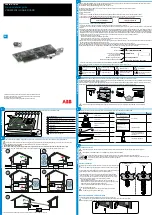
VSN300
Brand: ABB Pages: 2

VSN700
Brand: ABB Pages: 32

1750
Brand: Fluke Pages: 60

USB-9472
Brand: National Instruments Pages: 20

READy Mini Concentrator
Brand: Kamstrup Pages: 20

uR1800
Brand: YOKOGAWA Pages: 129

SmartLOG 2021
Brand: AccuTherm Pages: 12

TruBlue 255 LEVEL
Brand: TE Connectivity Pages: 26

MJK Chatter
Brand: Xylem Pages: 50

ST1046
Brand: iDuino Pages: 4

DT171
Brand: Elma Instruments Pages: 16

2420-EX
Brand: ELPRO Pages: 28

SymphoniePLUS
Brand: NRG Systems Pages: 2

GT-120B
Brand: Mobile Action Pages: 10

OOT550-DL3B2
Brand: AMIC Pages: 53


