manualshive.com logo in svg
background image

SERVICE STATION MANUAL

664711 IT-664712 EN-664713 FR-664714 DE-664715

ES-664716 PT-664717 OL-664718 EL

XEVO 125 Euro 3

Содержание XEVO 125 Euro 3

Страница 1: ...SERVICE STATION MANUAL 664711 IT 664712 EN 664713 FR 664714 DE 664715 ES 664716 PT 664717 OL 664718 EL XEVO 125 Euro 3 ...

Страница 2: ...s to components parts or accessory supplies which it considers necessary to improve the product or which are required for manufacturing or construction reasons Not all versions shown in this publication are available in all Countries The availability of individual versions should be confirmed with the official Piaggio sales network Copyright 2007 PIAGGIO C S p A Pontedera All rights reserved Repro...

Страница 3: ...able to read the sections of this manual concerning special tools along with the special tool catalogue N B Provides key information to make the procedure easier to understand and carry out CAUTION Refers to specific procedures to carry out for preventing damages to the vehicle WARNING Refers to specific procedures to carry out to prevent injuries to the repairer Personal safety Failure to complet...

Страница 4: ......

Страница 5: ...S CHAR TOOLING TOOL MAINTENANCE MAIN TROUBLESHOOTING TROUBL ELECTRICAL SYSTEM ELE SYS ENGINE FROM VEHICLE ENG VE ENGINE ENG SUSPENSIONS SUSP BRAKING SYSTEM BRAK SYS COOLING SYSTEM COOL SYS CHASSIS CHAS PRE DELIVERY PRE DE TIME TIME ...

Страница 6: ......

Страница 7: ...INDEX OF TOPICS CHARACTERISTICS CHAR ...

Страница 8: ...mpressed air in such a way that you do not breathe in the dust produced by the wear of the friction material Even though the latter contains no asbestos inhaling dust is harmful Maintenance rules Use original PIAGGIO spare parts and lubricants recommended by the Manufacturer Non original or non conforming spares may damage the vehicle Use only the appropriate tools designed for this vehicle Always...

Страница 9: ...Vehicle identification Chassis prefix M36601 Engine prefix M368M Dimensions and mass XEVO 125 Euro 3 Characteristics CHAR 3 ...

Страница 10: ...2 Nm at 8 000 rpm Lubrication Engine lubrication with lobe pump inside crank case controlled by a chain with double filter mesh and paper Lubrication pressure 4 bar Minimum lubrication pressure 100 C 0 8 bar Fuel supply KEIHIN CVEK 30 carburettor and electrical fuel pump Cooling Forced coolant circulation system Fuel Unleaded petrol 95 RON Exhaust muffler absorption type exhaust muffler with catal...

Страница 11: ...ons FRAME AND SUSPENSIONS Specification Desc Quantity Chassis Tubular and sheet steel Front suspension Hydraulic telescopic fork with Ø 35 mm stem Front suspension travel 90 mm Rear suspension Two double acting shock absorbers adjustable to four positions at preloading Rear suspension travel 90 mm Brakes BRAKES Specification Desc Quantity Front brake Ø 260 mm disc brake with hydraulic control acti...

Страница 12: ...m jet 38 Max air jet 70 Minimum air jet 130 Throttle valve spring 100 160 g Minimum mixture set screw initial opening 1 Tapered pin Ø 2 49 Diffuser nozzle Ø 2 8 Starter air jet Ø 1 5 Starter jet 42 Starter device resistance 20 Ω Starter pin travel 10 Tightening Torques REAR BRAKE Name Torque in Nm Rear brake disc screws 5 6 5 Rear brake calliper pipe fitting 20 25 Rigid flexible pipe fitting 13 18...

Страница 13: ...wheel shaft 45 50 Fork plate screw 25 34 CHASSIS Name Torque in Nm Centre stand bolt 25 30 Side stand bolt 35 40 Engine arm bolt frame arm 33 41 Swinging arm buffer nut 64 72 Frame swinging arm bolt 64 72 Engine swinging arm bolt 64 72 CHASSIS Product Description Specifications Loctite 243 Medium strength threadlock Apply LOCTITE 243 medium strength threadlock STEERING Name Torque in Nm Upper stee...

Страница 14: ...ENGINE CYLINDER HEAD Name Torque in Nm Manifold silencer retaining bolt 15 20 Nut fixing muffler to cylinder head 16 18 Camshaft retention plate screw 4 6 Timing chain tensioner central screw 5 6 Timing chain tensioner support screw 11 13 Starter ground support screw 11 15 Timing chain tensioner slider screw 10 14 Inlet manifold screws 11 13 Tappet set screw lock nut 6 8 Starter ground screw 7 8 5...

Страница 15: ...11 57 018 56 959 56 966 0 045 0 059 Piston D 57 018 57 025 56 966 56 973 0 045 0 059 Cylinder 1st Over size A1 57 197 57 204 57 145 57 152 0 045 0 059 Cylinder 1st Over size B 1 57 204 57 211 57 152 57 159 0 045 0 059 Piston 1st Over size C 1 57 211 57 218 57 159 57 166 0 045 0 059 Piston 1st Over size D 1 57 218 57 225 57 166 57 173 0 045 0 059 Cylinder 2nd Over size A2 57 397 57 404 57 345 57 35...

Страница 16: ...ame Description Dimensions Initials Quantity Crankshaft half bearing Category B blue 1 973 1 976 Crankshaft half bearing Type C yellow 1 976 1 979 Crankshaft half bearing Category E green 1 979 1 982 CRANKCASE CRANKSHAFT COUPLINGS Name Description Dimensions Initials Quantity Crankshaft catego ry 1 Crankcase category 1 E E Crankshaft catego ry 1 Crankcase category 2 C C Crankshaft class 2 Crankcas...

Страница 17: ...Fitting clearances Crankshaft crankcase axial clearance H 0 15 0 40 mm when cold XEVO 125 Euro 3 Characteristics CHAR 11 ...

Страница 18: ...a value of piston protrusion It indicates by how much the plane formed by the piston crown protrudes from the plane formed by the upper part of the cylinder The further the piston protrudes from the cylinder the thicker the base gasket to be used to restore the compression ratio and vice versa N B NO GASKETS AND SEALS SHOULD BE ASSEMBLED BETWEEN THE CRANKCASE AND CYL INDER AND THE DIAL GAUGE EQUIP...

Страница 19: ...er The further the piston protrudes from the cylinder the thicker the base gasket to be used to restore the compression ratio and vice versa N B NO GASKETS AND SEALS SHOULD BE ASSEMBLED BETWEEN THE CRANKCASE AND CYL INDER AND THE DIAL GAUGE EQUIPPED WITH SUPPORT SHOULD BE SET TO ZERO FOR MEASUREMENT A TO BE TAKEN WITH THE PISTON AT TOP DEAD CENTRE POSITION AND ON A RECTIFIED PLANE MODELS WITH META...

Страница 20: ...aper ring 1st Oversize 57 2 x 1 A 0 10 0 30 Oil scraper ring 1st Oversize 57 2 x 2 5 A 0 15 0 35 Compression ring 2nd Oversize 57 4 x 1 A 0 15 0 30 Oil scraper ring 2nd Oversize 57 4 x 1 A 0 10 0 30 Oil scraper ring 2nd Oversize 57 4 x 2 5 A 0 15 0 35 Compression ring 3rd Oversize 57 6 x 1 A 0 15 0 30 Oil scraper ring 3rd Oversize 57 6 x 1 A Oil scraper ring 3rd Oversize 57 6 x 2 5 A 0 15 0 35 Cha...

Страница 21: ... FILTER OIL Oil for air filter sponge Mineral oil with specific additives for increased adhesiveness AGIP GP 330 Grease for brake levers throttle White calcium complex soap based spray grease with NLGI 2 ISO L XBCIB2 AGIP CITY HI TEC 4T Engine oil SAE 5W 40 API SL ACEA A3 JASO MA Synthetic oil AGIP BRAKE 4 Brake fluid FMVSS DOT 4 Synthetic fluid SPECIAL AGIP PERMANENT fluid coolant Monoethylene gl...

Страница 22: ...Characteristics XEVO 125 Euro 3 CHAR 16 ...

Страница 23: ...INDEX OF TOPICS TOOLING TOOL ...

Страница 24: ...OLS Stores code Description 020151Y Air heater 020331Y Digital multimeter 020333Y Single battery charger 020334Y Multiple battery charger 001467Y014 Pliers to extract ø 15 mm bear ings Tooling XEVO 125 Euro 3 TOOL 2 ...

Страница 25: ...Stores code Description 020412Y 15 mm guide 020335Y Magnetic support for dial gauge 020565Y Flywheel lock calliper spanner 020439Y 17 mm guide 020359Y 42x47 mm adaptor XEVO 125 Euro 3 Tooling TOOL 3 ...

Страница 26: ... 20 mm guide 020459Y Punch for fitting bearing on steer ing tube 020458Y Puller for lower bearing on steer ing tube 005095Y Engine support 008564Y Flywheel extractor 020434Y Oil pressure control fitting Tooling XEVO 125 Euro 3 TOOL 4 ...

Страница 27: ...ter for valve removal tool 020424Y Driven pulley roller casing fitting punch 020431Y Valve oil seal extractor 020193Y Oil pressure gauge 020306Y Punch for assembling valve seal rings 020360Y Adaptor 52 x 55 mm XEVO 125 Euro 3 Tooling TOOL 5 ...

Страница 28: ... mm guide 020375Y Adaptor 28 x 30 mm 020376Y Adaptor handle 020444Y Tool for fitting removing the driv en pulley clutch 020330Y Stroboscopic light for timing con trol 001467Y035 Belle for OD 47 mm bearings Tooling XEVO 125 Euro 3 TOOL 6 ...

Страница 29: ...ing pulley lock wrench 020319Y Immobilizer check tester 020287Y Clamp to assemble piston on cyl inder 020263Y Sheath for driven pulley fitting 020262Y Crankcase splitting strip 020430Y Pin lock fitting tool XEVO 125 Euro 3 Tooling TOOL 7 ...

Страница 30: ...on 020428Y Piston position check support 020426Y Piston fitting fork 020425Y Punch for flywheel side oil seal 020423Y driven pulley lock wrench 020414Y 28 mm guide 020393Y Piston fitting band Tooling XEVO 125 Euro 3 TOOL 8 ...

Страница 31: ...382Y Valve cotters equipped with part 012 removal tool 020455Y 10 mm guide 020442Y Pulley lock wrench 020440Y Water pump service tool 020329Y MityVac vacuum operated pump 020357Y 32 x 35 mm adaptor XEVO 125 Euro 3 Tooling TOOL 9 ...

Страница 32: ...409Y Multimeter adaptor Peak volt age detection 020456Y Ø 24 mm adaptor 020332Y Digital rev counter 020074Y Support base for checking crank shaft alignment 020055Y Wrench for steering tube ring nut Tooling XEVO 125 Euro 3 TOOL 10 ...

Страница 33: ... 001330Y Tool for fitting steering seats 020454Y Tool for fitting piston pin stops 200 250 020622Y Transmission side oil guard punch 020444Y011 adapter ring 020444Y009 46x55 Wrench 001467Y Extractor for bearings for holes XEVO 125 Euro 3 Tooling TOOL 11 ...

Страница 34: ...Stores code Description 001467Y013 Pliers to extract ø 15 mm bear ings 020444Y010 adapter ring Tooling XEVO 125 Euro 3 TOOL 12 ...

Страница 35: ...INDEX OF TOPICS MAINTENANCE MAIN ...

Страница 36: ...o longer dis played Maintenance chart EVERY 2 YEARS Action Coolant change Brake fluid change secondary air filter outside cleaning EVERY 3 000 KM 10 Action Engine oil level check top up AFTER 1 000 KM 65 Action Engine oil replacement Hub oil change Idle speed adjustment Throttle lever adjustment Steering adjustment Brake control levers greasing Brake pads check condition and wear Brake fluid level...

Страница 37: ...r adjustment Driven pulley roller casing Greasing Driving belt replacement Sliding blocks variable speed rollers check Coolant level check Steering adjustment Brake control levers greasing Brake pads check condition and wear Brake fluid level check Transmission elements lubrication Safety locks check Suspensions check Electrical system and battery check Headlight adjustment Tyre pressure and wear ...

Страница 38: ...ake control levers greasing Brake pads check condition and wear Brake fluid level check Transmission elements lubrication Safety locks check Suspensions check Electrical system and battery check Headlight adjustment Tyre pressure and wear check Vehicle and brake test road test See instructions in Idle speed adjustment section AFTER 30 000 KM 42 000 KM 66 000 KM 90 Action Engine oil change Engine o...

Страница 39: ...justment Tyre pressure and wear check Vehicle and brake test road test See instructions in Idle speed adjustment section AFTER 72 000 KM 270 Action Engine oil replacement Engine oil change Hub oil change Spark plug electrode gap check replacement Valve clearance check Air filter clean Idle speed adjustment Throttle lever adjustment Driving belt replacement Sliding block variable speed rollers chan...

Страница 40: ...S Checking the spark advance To check ignition advance use the stroboscopic light with induction pincers connected to the spark plug power wire Connect the induction pincers being careful to respect the proper polarity the arrow stamped on the pincers must be pointing at the spark plug Place the light selector in central position 1 spark 1 crankshaft turn as in 2 T engines Start the engine and che...

Страница 41: ... the fixing screw of the right side lid on the right rear fairing and remove it Remove the spark plug cap Use the supplied spanner with retaining rubber ring to remove the spark plug Disconnect and remove the spark plug cable Examine it carefully and replace it if the insulator is chipped or cracked Measure electrode gap with a thickness gauge and if necessary adjust the gap by carefully bend ing ...

Страница 42: ...place 3 Pull out the dipstick and check that the oil level is above the first notch from the bottom If the oil level is below the Max notch refill the hub with the adequate amount of oil 4 Screw the dipstick back in checking that it is locked in place N B THE REFERENCE MARKS ON THE HUB OIL LEVEL DIPSTICK EXCEPT FOR THE ONE IN DICATING THE MAX LEVEL REFER TO OTH ER MODELS BY THE MANUFACTURER AND HA...

Страница 43: ...0 rear oil hub SAE 80W 90 Oil that exceeds the requirements of API GL3 specifications Characteristic Transmission oil 150 cm Replacement Remove the oil cap A Unscrew the oil drainage cap B and drain out all the oil Screw in the drainage cap again and fill the hub with the prescribed oil Recommended products AGIP ROTRA 80W 90 Rear hub oil SAE 80W 90 Oil that exceeds the requirements of API GL3 spec...

Страница 44: ...ne oil In 4T engines engine oil is used to lubricate the distribution elements main bearings and thermal group An insufficient quantity of oil can cause serious damage to the engine itself In all four stroke engines a loss of efficiency in oil performance and consumption should be considered normal Con sumption can particularly reflect the conditions of use i e when driving at full acceleration al...

Страница 45: ...e new cartridge filter being careful to lubri cate the O ring before fitting it Change the engine oil Since a certain quantity of oil still remains in the circuit engine oil must be added through the plug A Then start up the scooter leave it running for a few minutes and switch it off after five minutes check the level and if necessary top up without exceeding the MAX level The cartridge filter mu...

Страница 46: ...pstick A again and check that the level is between the MAX and MIN marks top up if required If the check is carried out after the vehicle has been used and therefore with a hot engine the level line will be lower in order to carry out a cor rect check wait at least 10 minutes after the en gine has been stopped so as to get the correct level Oil top up Always check the oil level before topping up i...

Страница 47: ...cator on the head turn the crankshaft once more N B TIME THE TIMING SYSTEM UNIT IF IT IS NOT IN PHASE Checking the valve clearance To check valve clearance centre the reference marks of the timing system Use a thickness gauge to check that the clear ance between the valve and the register corre sponds with the indicated values When the valve clearance values intake and drainage respective ly are d...

Страница 48: ...nd MAX level CAUTION DO NOT EXCEED THE MAX LEVEL WHEN FILLING SO AS TO AVOID THE COOLANT ES CAPING FROM THE EXPANSION TANK WHEN THE vehicle IS IN USE Recommended products SPECIAL AGIP PERMANENT fluid coolant Monoethylene glycol based antifreeze fluid CU NA NC 956 16 Braking system Level check The front and rear brake fluid reservoirs are both positioned on the handlebars Proceed as follows Rest th...

Страница 49: ...r the front brake pump Under standard climatic conditions replace cool ant as indicated in the scheduled maintenance table WARNING ONLY USE DOT 4 CLASS BRAKE FLUIDS COOLING SYSTEM FLUIDS ARE HIGHLY COR ROSIVE MAKE SURE THAT IT DOES NOT COME INTO CONTACT WITH THE PAINT WORK CAUTION MAKE SURE THE BRAKE FLUID DOES NOT GET INTO YOUR EYES OR ON YOUR SKIN OR CLOTHES IF THIS HAPPENS ACCIDENTALLY WASH WIT...

Страница 50: ... central screw A underneath the Piaggio badge N B THE ABOVE PROCEDURE COMPLIES WITH THE EUROPEAN STANDARDS REGARDING MAXIMUM AND MINIMUM HEIGHT OF LIGHT BEAMS REFER TO THE STATUTORY REGU LATIONS IN FORCE IN EVERY COUNTRY WHERE THE vehicle IS USED SAS filters inspection and cleaning Remove the secondary air filter cover after undo ing the 3 fixing screws A then remove the fil tering element B Wash ...

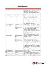
Страница 51: ...INDEX OF TOPICS TROUBLESHOOTING TROUBL ...

Страница 52: ...quired Oil level exceeds maximum Check for causes and fill to reach the correct level Lack of compression parts cylinder and valves worn Replace the worn parts Transmission belt worn Replace Inefficient automatic transmission Check the rollers the pulley movement and make sure the drive belt is in good conditions replace the damaged parts and lubricate the moveable driven pulley with specific grea...

Страница 53: ...ttery following the instructions shown in the chapter Intake coupling cracked or clamps incorrectly tightened Replace the intake coupling and check the clamps are tightened Defective floating valve Check the proper sliding of the float and the func tioning of the valve Carburettor nozzles clogged Dismantle wash with solvent and dry with com pressed air Fuel pump fault Check the pump control device...

Страница 54: ...that the air calibra tion elements are clean check if the sponge filter is clean too Incorrect idle adjustment Adjust using the rpm indicator Pressure too low at the end of compression Check the thermal group seals and replace worn components Faulty spark plug or incorrect ignition advance Replace the spark plug or check the ignition circuit components The starter remains on Check electric wiring ...

Страница 55: ...sible Cause Operation Secondary air device cut off valve not working Replace the secondary air device Depression intake pipe of the secondary air device disconnected or dented Replace the pipe Reed valve of the secondary air device does not close correctly and wears out the rubber coupling between the device and the head pipe Replace the device and the coupling Transmission and brakes Clutch grabb...

Страница 56: ...ft of the disc Defective piston sliding Check calliper and replace any damaged part Electrical system Battery BATTERY Possible Cause Operation Battery This is the device in the system that requires the most frequent attention and the most thorough maintenance If the vehicle is not used for some time 1 month or more the battery needs to be re charged periodically The battery runs down com pletely i...

Страница 57: ...g the above adjustments check the seats in which the ball bearings rotate if they are recessed or if the balls are squashed replace them Malfunctions in the suspension system If the front suspension is noisy check the efficien cy of the front shock absorbers the condition of the ball bearings and relevant lock nuts the limit switch rubber buffers and the movement bushings In conclusion check the t...

Страница 58: ...Troubleshooting XEVO 125 Euro 3 TROUBL 8 ...

Страница 59: ...INDEX OF TOPICS ELECTRICAL SYSTEM ELE SYS ...

Страница 60: ...tor 7 Main fuses 8 Plug socket 9 Battery 10 Starter motor 11 Start up remote control switch 12 Start up button 13 Secondary fuses 14 Stop button on rear brake 15 Stop button on front brake 16 Boot opening switch 17 Rear boot actuator 18 Saddle opening actuator 19 Electrical actuators control unit Electrical system XEVO 125 Euro 3 ELE SYS 2 ...

Страница 61: ...ront light A Tail light bulbs B Low beam light bulb C High beam light bulb 34 Front right turn indicator 35 Ambient temperature sensor 36 Remote control headlight 37 Engine oil pressure sensor 38 Horn 39 Horn button 40 MODE button 41 Thermistor 42 Instrument panel 43 Wheel turning sensor 44 Fuel level transmitter 45 Light switch remote control 46 Thermoswitch 47 Electric fan 48 Fuel electric pump ...

Страница 62: ...ed Ve Green Vi Purple Conceptual diagrams Ignition KEY 1 Electronic ignition device 2 Immobilizer aerial 5 Engine stop switch 7 Main fuses 9 Battery 49 Key switch 51 Spark plug 52 HV coil Electrical system XEVO 125 Euro 3 ELE SYS 4 ...

Страница 63: ... Battery 13 Secondary fuses 26 Light switch 28 Licence plate light bulb 30 Rear light B Tail light bulbs 33 Front light A Tail light bulbs B Low beam light bulb C High beam light bulb 36 Remote control headlight 42 Instrument panel 49 Key switch 53 Automatic starter XEVO 125 Euro 3 Electrical system ELE SYS 5 ...

Страница 64: ...ine stop switch 6 Voltage regulator 7 Main fuses 9 Battery 10 Starter motor 11 Start up remote control switch 12 Start up button 13 Secondary fuses 14 Stop button on rear brake 15 Stop button on front brake 30 Rear light A Stop light bulbs 49 Key switch Electrical system XEVO 125 Euro 3 ELE SYS 6 ...

Страница 65: ...mmobilizer aerial 5 Engine stop switch 7 Main fuses 9 Battery 13 Secondary fuses 35 Ambient temperature sensor 37 Engine oil pressure sensor 41 Thermistor 42 Instrument panel 43 Wheel turning sensor 44 Fuel level transmitter 49 Key switch XEVO 125 Euro 3 Electrical system ELE SYS 7 ...

Страница 66: ...13 Secondary fuses 16 Boot opening switch 17 Rear boot actuator 18 Saddle opening actuator 19 Electrical actuators control unit 20 Wiring for antitheft device 21 Hazard button 22 Turn indicator switch 23 Turn indicator control device 24 Helmet compartment light switch 25 Rear case light switch Electrical system XEVO 125 Euro 3 ELE SYS 8 ...

Страница 67: ...ic ignition system is fed with direct cur rent and is protected by an antitheft immobilizer integrated to the control unit The ignition system consists of electronic control unit immobilizer aerial master and service keys with built in transponder H V coil diagnosis LED The diagnosis LED also works as a theft deterring blinker This function is activated every time the key switch is turned to OFF a...

Страница 68: ...ector and check if There is battery voltage between the terminal No 3 Red and the ground connection There is battery voltage between terminal No 3 Red and terminal No 6 Negative as shown in the figure If no voltage is detected check the wiring to the battery positive lead and see if the 15A fuse is in good conditions There is battery voltage between terminals No 1 and No 6 with the key switch set ...

Страница 69: ... be necessary to repeat the procedure from the start Once the control unit has been programmed the control unit is inseparably matched with the MAS TER key transponder This matching allows programming further service keys in case of loss replacement etc Each new time new data is programmed the previously stor ed one is deleted If a service key setting is lost it is essential to carefully check the...

Страница 70: ...connector from the control unit and check the aerial continuity with the 020331Y multimeter If non conforming values are measured replace the aerial If no failures are found in the aerial replace the control unit CAUTION BEFORE PROGRAMMING THE NEW ELECTRONIC CONTROL UNIT CHECK THAT NO FAILURE CODE IS INDICATED THIS IS NECESSARY TO AVOID SPOILING A NEW CONTROL UNIT Electric characteristic immobiliz...

Страница 71: ...ition system The Pick Up is connected to the control unit by a single cable then for the ground circuit the control unit is connected to the Pick Up by the chassis and the engine ground lead To avoid disturbances in the ignition system during start up it is very important that the engine chassis ground connection bonding is efficient No spark plug Once the lack of power to the spark plug has been ...

Страница 72: ...con forming values are measured check the wiring If failures are detected check the HV coil secondary Electric characteristic High voltage coil primary resistance value High voltage coil primary resistance value 0 4 0 5 Ohm HV coil secondary check Disconnect the spark plug cap from the HV cable and measure the resistance between the HV cable terminal and the HV coil negative terminal see figure If...

Страница 73: ...ring the start up test with the voltage peak adaptor and con necting the positive terminal to the ground one and the negative to the coil positive connector If non conforming values are measured replace the control unit N B THE PLASTIC CAP OF THE POSITIVE TERMI NAL ON THE HV COIL PRIMARY IS BLACK AND THE NEGATIVE TERMINAL ONE IS GREEN Electric characteristic High voltage coil voltage value High vo...

Страница 74: ... 5 earth 3 earth 1 earth Stage indicative resistance 0 7 0 9 Ω Minimum oil pressure switch check With a tester check the circuit between connec tions 4 and ground with engine off is not inter rupted Pick Up check Check that there is a resistance of approx 105 124 Ω at 20 C between connection 6 and the ground lead In case values different from the ones stated are detected replace the defective part...

Страница 75: ...ated by the system with lights on and a high running engine In case the generated current value is lower than 10A repeat the test using a new regulator and stator alternatively Choke Inspection Refer to the engine section to check the resistance and operating conditions of the component As re gards voltage supply keep the connector connec ted to the system and check that the two terminals receive ...

Страница 76: ... check the white pink cable of the turn indicator switch for voltage Keep the switch activated to the left If there is voltage check the turn indicator management device otherwise check the orange white cable of the switch again If there is voltage in the cable replace the turn indicator switch because it is faulty otherwise check cable harness and repeat the procedure Check the turn indicator man...

Страница 77: ...indicator bulb Type ALL GLASS Power 12V 5W Quantity 2 RHS 2 LHS 8 Rear tail light bulb Type ALL GLASS Power 12V 5W Quantity 2 9 Stop light bulb Type SPHERICAL Power 12V 10W Quantity 2 10 License plate light bulb Type ALL GLASS Power 12V 5W Quantity 1 Fuses The electrical system is equipped with 12 protec tive fuses for the various circuits on the vehicle subdivided into two fuse boxes A and B lo c...

Страница 78: ...ery compartment on left side of the vehicle 2 Fuse No 2 Capacity 15A Protected circuits Electric fan battery powered electronic igni tion device Live power supply to load fuses no 7 8 10 12 light remote control engine stop switch automatic starter electronic ignition device Location Battery compartment on left side of the vehicle 3 Fuse No 3 Capacity 15A Protected circuits Battery powered plug soc...

Страница 79: ...er supply to horn switch light Location Battery compartment on vehicle RHS 9 Fuse No 9 Capacity 7 5 A Protected circuits Live power supply to tail lights license plate light instrument panel lightning Location Battery compartment on vehicle RHS 10 Fuse No 10 Capacity 7 5 A Protected circuits Live power supply to wheel revolution sensor digital display in strument panel warning lights Location Batt...

Страница 80: ... CLOCK button for less than 1 sec ond displays the following sequence TIME DATE To set the clock push and hold the CLOCK but ton longer than 3 seconds The numbers showing the hours will begin flash ing Set the hour using the SET button Push the CLOCK button again and the minutes numbers start flashing Set the minutes using the SET button Push the CLOCK button again and the day numbers start flashi...

Страница 81: ...al recharge If voltage is below 12 60 V a renewal recharge is required as explained in 2 2 Constant voltage battery charge mode Constant voltage charge equal to 14 40 14 70V Initial charge voltage equal to 0 3 0 5 for Nominal capacity Charge time 10 to 12 h recommended Minimum 6 h Maximum 24 h 3 Constant current battery charge mode Charge current equal to 1 10 of the nominal capacity of the batter...

Страница 82: ... with distilled water Before 24 hours elapse recharge the battery following these steps Connect the battery charger terminals observing the correct polarity Wit the battery charger drw 020333Y and or drw 020334Y operate the battery charger control by selecting the position corresponding to that capacity Otherwise charge the battery with direct current equal to 1 10 of rated capacity e g for a batt...

Страница 83: ...of the connector of the fuel pump control device and the negative probe to pin 3 making sure there is bat tery voltage as indicated in the table PUMP SUPPLY Specification Desc Quantity Key set to KEY ON Supply to the pump for 13 seconds Engine revs from 0 to 200 rpm Always OFF Engine revs from 200 to 1200 rpm Always ON Engine revs from 1200 to 2000 rpm 0 2 seconds ON 9 seconds OFF Engine rpm 2000 ...

Страница 84: ...ound Black 6 Magneto flywheel Yellow AUTOMATIC STARTER CONNECTOR 1 Live positive Orange 2 Ground Brown TURN INDICATOR CONTROL DEVICE CON NECTOR 1 Hazard switch Brown 2 LHS Turn indicator switch White Pink 3 RHS Turn indicator switch Blue Black 4 LHS Turn indicator bulbs Pink 5 RHS Turn indicator bulbs White Blue 6 Battery powered Grey Green 7 Light switch remote control Purple White 8 Live Orange ...

Страница 85: ...l Purple INSTRUMENT PANEL CONNECTOR A 1 Not connected 2 Not connected 3 Not connected 4 Not connected 5 Instrument panel lighting Yellow Black 6 Battery powered Red Green 7 Not connected 8 Not connected 9 Not connected 10 Not connected 11 Ground Black 12 Live Grey Black INSTRUMENT PANEL CONNECTOR B 1 Speed sensor Green 2 Fuel level indicator White Green 3 Thermistor Yellow Green 4 Water temperatur...

Страница 86: ...tor Blue 12 Ambient temperature sensor White Yellow 13 Ambient temperature sensor negative Yellow Blue 14 Engine stop switch Sky Blue 15 Immobilizer LED Yellow 16 Engine check warning light Brown Black 17 Ground Black 18 Hazard warning light Purple Black 19 Ground Ground 20 Not connected Electrical system XEVO 125 Euro 3 ELE SYS 28 ...

Страница 87: ...INDEX OF TOPICS ENGINE FROM VEHICLE ENG VE ...

Страница 88: ...anifold after that re move the muffler backwards Unscrew the 2 nuts that fix the exhaust manifold to the head and remove it Removal of the engine from the vehicle Remove the side panels Undo the 2 screws fixing the rear brake calliper to the supporting arm and re move it Keep the pipes connected to the cal liper and move it aside towards the vehicle front part so as not to hinder the next removal ...

Страница 89: ...the holding spring and re move the coolant out pipes Remove the holding spring and re move the petrol pump low pressure pipe from the inlet manifold Move the accelerator wire from the throttle control rocking lever unscrew the set screw and disconnect the trans mission from the carburettor XEVO 125 Euro 3 Engine from vehicle ENG VE 3 ...

Страница 90: ...ng the rubber cap Remove the holding spring and move the petrol feed pipe to carburettor Cut the plastic clamp and disconnect the starter supply connection Remove the lower screws fastening the rear shock absorbers to the engine crankcase and the supporting arm Engine from vehicle XEVO 125 Euro 3 ENG VE 4 ...

Страница 91: ...emove the footrest and the left side fairing move the lower central cover slightly to the outside and remove the three screws fixing the supporting plate of the swinging arm buffer Remove the buffer sealing seeger ring and remove the supporting plate of the swinging arm buffer Support the vehicle adequately with the jack Remove the engine swinging arm fixing pin by acting on the nut and the pin he...

Страница 92: ...Locking torques N m Engine swinging arm pin nut 33 41 Shock ab sorber lower clamp 33 41 Rear brake calliper tightening screws 20 25 Engine from vehicle XEVO 125 Euro 3 ENG VE 6 ...

Страница 93: ...INDEX OF TOPICS ENGINE ENG ...

Страница 94: ... Using the clutch bell lock wrench shown in the figure remove the driven pulley shaft locking nut and washer Specific tooling 020423Y driven pulley lock wrench Remove the cap dipstick from the engine oil filling hole A Remove the ten screws Remove the transmission cover If this operation is carried out directly on the vehi cle remove the cooling air supply coupling of the transmission housing Air ...

Страница 95: ...andle 020375Y Adaptor 28 x 30 mm 020412Y 15 mm guide Refitting the driven pulley shaft bearing Slightly heat the crankcase from the inside so as not to damage the painted surface Insert the bearing in its seat Refit the Seeger ring CAUTION USE AN APPROPRIATE REST SURFACE TO AVOID DAMAGING THE COVER PAINT N B ALWAYS REPLACE THE BEARING WITH A NEW ONE UPON REFITTING Specific tooling 020376Y Adaptor ...

Страница 96: ...d Measure the clutch bell inside diameter Characteristic Max value clutch bell Max value Ø 134 5 mm Clutch bell standard value Standard value Ø 134 134 2 mm Checking the bell working surface eccentricity Install the bell on a driven pulley shaft using 2 bearings inner diameter 15 and 17 mm Lock with the original spacer and nut Place the bell shaft assembly on the support to check the crankshaft al...

Страница 97: ...he tool internal side Insert the adapter ring No 8 in the pins Assemble the driven pulley unit on the tool intro ducing the rivets heads in the adapter ring Make sure that the clutch is perfectly inserted into the adapter ring before proceeding to loosen tight en the clutch nut Use the special 46x55 wrench component No 9 to remove the nut fixing the clutch in place Separate the driven pulley compo...

Страница 98: ...S CAN CAUSE THE CLUTCH TO TEAR CAUTION DO NOT OPEN THE MASSES USING TOOLS TO PREVENT A VARIATION IN THE RETURN SPRING LOAD Characteristic Check minimum thickness 1 mm Pin retaining collar Simultaneously turn and pull the collar manually to remove it N B USE TWO SCREWDRIVERS IF YOU HAVE DIF FICULTY N B BE CAREFUL NOT TO PUSH THE SCREW DRIVERS IN TOO FAR TO AVOID DAMAGE THAT COULD ENDANGER THE O RIN...

Страница 99: ...c tooling 001467Y035 Belle for OD 47 mm bearings Remove the roller bearing using the modular punch Specific tooling 020376Y Adaptor handle 020456Y Ø 24 mm adaptor 020363Y 20 mm guide Inspecting the driven fixed half pulley Measure the outer diameter of the pulley bushing Check the faying surface with the belt to make sure there are no flaws Check the riveted joints are functional Check the evennes...

Страница 100: ...ion Desc Quantity Wear limit 0 3 mm standard diameter Diameter 41 000 41 035 mm maximum allowable diameter Ø 41 08 mm Refitting the driven half pulley bearing Support the pulley bushing adequately from the threaded side using a wooden surface Fit a new roller sleeve as in the figure For the fitting of the new ball bearing follow the example in the figure using a modular punch Fit the retention rin...

Страница 101: ...ed to refitting them in their slots Refit the torque server closure collar Using a curved spout grease gun lubricate the driven pulley assembly with approximately 6 g of grease Apply the grease through one of the holes in the bushing until it comes out through the hole on the opposite side This operation is necessary to avoid the presence of grease beyond the O rings N B THE TORQUE SERVER CAN BE G...

Страница 102: ... mm Refitting the clutch Support the driven pulley spring compressor ap propriate tool with the control screw in vertical axis Arrange the tool with the medium length pins screwed on the inside Insert the adapter ring No 8 in the pins Preassemble the cooling fan to the clutch in such a way that the keying facets are aligned and the 3 pin heads A of the fulcrum axis can be seen in full Insert the c...

Страница 103: ...tool Preload the clutch return spring with a traction rotation combined action until it reaches the pul leys maximum opening and place the belt on the minimum rolling diameter Remove the driven pulley belt unit from the tool N B FOR DESIGN REASONS THE NUT IS SLIGHT LY ASYMMETRIC THE FLATTEST SURFACE SHOULD BE MOUNTED IN CONTACT WITH THE CLUTCH N B DURING THE SPRING PRELOADING PHASE BE CAREFUL NOT ...

Страница 104: ...k the width of the belt Characteristic Driving belt minimum width 21 5 mm Driving belt standard width 22 5 0 2 mm During the wear check foreseen in the scheduled maintenance check that the rim bottom of the toothing does not show signs of scores or cracking see figure otherwise replace the belt Engine XEVO 125 Euro 3 ENG 12 ...

Страница 105: ...e Check that the internal bushing shown in the fig ure is not abnormally worn and measure inner diameter A Measure the pulley sliding bushing outside di ameter shown in the figure Check that the rollers are not damaged or worn Check the guide shoes for the variator back plate are not worn Check the wear of the roller housings and of the belt faying surfaces on both pulley halves Check that station...

Страница 106: ...Diameter 26 000 26 021 mm Refitting the driving pulley Preassemble the movable half pulley with the roller contrast plate by putting the rollers in their housings with the larger support surface touching the pulley according to the direction of rotation Check that the roller contact plate does not have flaws and is not damaged on the grooved edge Mount the complete bushing unit on the driving shaf...

Страница 107: ...ribed torque Avoid the half pulley rotation with the appropriate stop key tool Rotate the engine manually until the belt is slight ly taut CAUTION IT IS EXTREMELY IMPORTANT THAT THE BELT IS PERFECTLY FREE WHEN THE FIXED DRIVING HALF PULLEY IS ASSEMBLED THIS IS TO AVOID CARRYING OUT A WRONG TIGHTENING OF THE DRIVING HALF PULLEY Specific tooling 020368Y driving pulley lock wrench Locking torques N m...

Страница 108: ...l washer and the driven pulley nut Tighten the nut to the prescribed torque using the lock wrench and the torque wrench tools Replace the plastic cover Specific tooling 020423Y driven pulley lock wrench Locking torques N m Transmission cover screws 11 13 Driven pul ley shaft nut 54 60 End gear Removing the hub cover Empty the rear hub through the oil drainage plug Remove the 7 flanged screws indic...

Страница 109: ...Check the state of the bearings being examined wear clearance and noisiness If faults are de tected do the following Use the specific bearing extractor to remove the three 15 mm bearings 2 in the crankcase and 1 in the hub cover Specific tooling 001467Y013 Pliers to extract ø 15 mm bearings XEVO 125 Euro 3 Engine ENG 17 ...

Страница 110: ...ft the corre sponding bearing and oil seal remove the trans mission cover and the clutch group as explained above Extract the driven pulley shaft from its bearing Remove the oil guard using a screwdriver work ing from inside the bearing and being careful not to damage the housing make it come out of the belt transmission side Remove the seeger ring shown in the figure With the sectional punch remo...

Страница 111: ...distorted Check the bearing bearings In case of anomalies replace the damaged components Refitting the wheel axle bearing Support the hub cover on a wooden surface Heat the cover crankcase with special heat gun Fit the wheel shaft bearing with a modular punch as shown in the figure Specific tooling 020150Y Air heater support 020151Y Air heater 020376Y Adaptor handle 020360Y Adaptor 52 x 55 mm 0204...

Страница 112: ...15 mm bearings must be fitted using the appropriate tools The 42 mm side of the adapter must be turned towards the bearing Refit the seeger ring with the opening facing the bearing and the new oil seal flush with the crank case on the pulley side Refit the driven pulley shaft bearing with a mod ular punch as shown in the figure Specific tooling 020150Y Air heater support 020151Y Air heater 020376Y...

Страница 113: ...n the figure Refitting the ub cover Fit a new gasket together with the centring dowels Seal the gasket of the breather pipe using black silicone sealant Fit the gearbox cover making sure the breather pipe is in the correct position Place the 3 shortest screws identifiable by their different colour as shown in the figure Fasten the breather pipe support bracket with the lower short screw Assemble t...

Страница 114: ...he 4 retainers and the flywheel cover Removing the stator Remove the electric terminal of the minimum oil pressure switch Remove the two Pick Up screws and the one for the wiring harness bracket as well as the two stator fixing screws shown in the figure Remove the stator and its wiring Engine XEVO 125 Euro 3 ENG 22 ...

Страница 115: ...s N m Stator assembly screws 3 4 Refitting the flywheel cover Place the flywheel with the top dead centre mark aligned with the crankcase Place the flywheel cover by aligning the reference marks of the drive and the crankcase cover Reassemble the cover on the engine placing the three connectors in the drive for the water pump Carry out the steps in the reverse order from the dismantling procedure ...

Страница 116: ...eel and the Pick Up control plate Refitting the flywheel magneto Fit the flywheel being careful to insert the key properly Lock the flywheel nut to the prescribed torque Check that the Pick Up air gap is between 0 34 0 76 mm The air gap cannot be modified when assembling the Pick Up Different values result from deformations visible on the Pick Up support N B A VARIATION IN THE AIR GAP DISTANCE MOD...

Страница 117: ... the two screws to the prescribed torque Locking torques N m Starter motor screws 11 13 Cylinder assy and timing system Removing the intake manifold Remove the flywheel cover completely as de scribed in the flywheel cover section Loosen the 3 crews and remove the intake mani fold N B SCREWS AGAINST ACCIDENTAL OPERA TION ARE PROVIDED XEVO 125 Euro 3 Engine ENG 25 ...

Страница 118: ...crankshaft and the sprocket wheel separation washer Remove the tappet cover Remove the central screw fastener and the au tomatic valve lifter retaining cover as shown in the figure Remove the return spring of the automatic valve lifter unit and the automatic valve lifter unit and its end of stroke washer Loosen the central screw on the tensioner first Remove the two fixings shown in the figure Rem...

Страница 119: ...pacer bar and the tensioner slider The chain tensioning pad must be removed from the transmission side As regards the lower chain guide pad it may only be removed after the head has been removed N B IT IS ADVISABLE TO MARK THE CHAIN IN OR DER TO ENSURE THAT THE INITIAL DIREC TION OF ROTATION IS MAINTAINED Removing the cam shaft Remove the two screws and the cam shaft retainer shown in the diagram ...

Страница 120: ...s from the flywheel side holes N B IN CASE OF NEED THE HEAD MAY BE RE MOVED WITH THE CAMSHAFT PINS ROCK ING LEVERS AND FIXING BRACKET THE HEAD CAN ALSO BE REMOVED WITHOUT RE MOVING THE CHAIN AND THE DRIVING SHAFT CHAIN TIGHTENER Engine XEVO 125 Euro 3 ENG 28 ...

Страница 121: ...ves Using the appropriate tool fitted with an adaptor remove the cotters caps springs and valves Remove the oil guards with the appropriate tool Remove the lower spring supports CAUTION REPLACE THE VALVES IN SUCH A WAY AS TO RECOGNISE THEIR ORIGINAL POSITION ON THE HEAD Specific tooling 020382Y011 adapter for valve removal tool 020382Y Valve cotters equipped with part 012 removal tool 020306Y Punc...

Страница 122: ...CAUTION TO AVOID DAMAGING THE PISTON SUPPORT IT WHILE REMOVING THE CYLINDER N B BE CAREFUL NOT TO DAMAGE THE SEALING RINGS DURING REMOVAL Engine XEVO 125 Euro 3 ENG 30 ...

Страница 123: ...y diameter on the piston Calculate the piston pin coupling clearance Measure the outside diameter of the piston per pendicular to the gudgeon pin axis Carry out the measurement as shown in the fig ure 41 1 mm from the crown Using a bore meter measure the inner cylinder diameter at three different points according to the directions shown in the figure Check that the head matching surface exhibits n...

Страница 124: ...EASON MEASURE MENT OF THE DIAMETER MUST BE CARRIED OUT ACCORDING TO THE AXIS OF THE PIS TON Characteristic Pin diameter Standard diameter 56 997 57 025 piston diameter 56 945 56 973 mm Pin diameter Standard clearance 0 015 0 029 mm Pin diameter Standard diameter 14 996 15 000 mm Wrist pin seat on the piston Standard diameter 15 001 15 006 mm Diameter of the wrist pin seat on the piston Standard cl...

Страница 125: ...its original di ameter Using the piston insert the rings perpendicularly to the cylinder axis Measure the opening see figure of the sealing rings using a feeler gauge If any measurements are greater than specified replace the piston rings N B BEFORE REPLACING ONLY THE PISTON RINGS ENSURE THAT THE CLEARANCE BETWEEN THE PISTON RINGS AND THE PISTON RING GROOVES AND BETWEEN THE PISTON AND THE CYLINDER...

Страница 126: ...ol With opening in the position indicated on the tool S left D right Place the wrist pin stop ring into position using a punch Fit the wrist pin stop using the plug as shown in the figure CAUTION USING A HAMMER MIGHT DAMAGE THE STOPS HOUSING N B THE TOOL FOR INSTALLING THE STOP RINGS MUST BE USED MANUALLY Specific tooling 020430Y Pin lock fitting tool Engine XEVO 125 Euro 3 ENG 34 ...

Страница 127: ...supplied nuts as shown in the figure Rotate the crankshaft until TDC the inverted point of the dial gauge rotation Position the dial gauge on the piston as shown in the figure and measure how much the piston pro trudes By means of the table shown in the specifications chapter identify the cylinder base gasket thickness to be used for refitting Correctly identify the cylin der base gasket thickness...

Страница 128: ...ence mark facing the crown of the piston Offset the piston ring gaps on the three rings by 120 to each other as shown in the figure Lubricate the components with engine oil N B THE TWO PISTON RINGS ARE MADE WITH A TAPERED CYLINDRICAL CONTACT CROSS SECTION THIS IS TO ACHIEVE A BETTER BEDDING Refitting the cylinder Insert the cylinder base gasket with the thickness determined above Using the fork su...

Страница 129: ...um allowable run out 0 05 mm Check that the camshaft and the rocker pin ca pacities exhibit no wear Check that the cylinder head cover surface the intake manifold and the exhaust manifold are not worn Characteristic bearing A Ø 12 000 12 018 mm bearing B Ø 20 000 20 021 mm bearing C Ø 37 000 37 025 mm XEVO 125 Euro 3 Engine ENG 37 ...

Страница 130: ...ve the centre screw with the washer and the tensioner spring Check that the one way mechanism is not worn Check the condition of the tensioner spring If examples of wear are found replace the whole assembly Inspecting the valve sealings Insert the valves into the cylinder head Alternatively check the intake and exhaust valves The test is carried out by filling the manifold with petrol and checking...

Страница 131: ...ter 5 000 5 012 mm Valve seat wear Exhaust guide Accepted limit 5 022 Valve seat wear Exhaust guide Standard diameter 5 000 5 012 mm Inspecting the valves Measure the diameter of the valve stems in the three positions indicated in the diagram Calculate the clearance between valve and valve guide Check that there are no signs of wear on the sur face of contact with the articulated register termi na...

Страница 132: ...ITTED IN Characteristic Valve check standard length Outlet 94 4 mm Valve check standard length Inlet 94 6 mm Valve check Maximum admissible clearance Outlet 0 072 mm Valve check Maximum admissible clearance Inlet 0 062 mm Valve check standard clearance Outlet 0 025 0 052 mm Valve check standard clearance Inlet 0 013 0 040 mm Valve check Minimum admissible diameter Outlet 4 95 mm Valve check Minimu...

Страница 133: ... springs and half cones Check that the upper and lower supporting wash ers of the springs the cotters and the oil seal do not show signs of abnormal wear Replace the components when worn XEVO 125 Euro 3 Engine ENG 41 ...

Страница 134: ... tool 020382Y011 adapter for valve removal tool Inspecting the cam shaft Inspect the cam shaft for signs of abnormal wear on the cams Check the cam height Check there is no wear on the cam shaft retaining plate and its associated groove on the cam shaft If any of the above dimensions are outside the specified limits or there are signs of excessive wear replace the defective components with new one...

Страница 135: ...m Cam shaft check Maximum admissible axial clearance 0 42 mm Cam shaft check Standard axial clearance 0 11 0 41 mm Cam shaft check Standard height Outlet 29 209 mm Cam shaft check Standard height Inlet 30 285 mm Cam shaft check Minimum admissible diame ter Bearing B diameter 19 950 mm Cam shaft check Minimum admissible diame ter Bearing A Ø 36 94 mm Cam shaft check Standard diameter Bearing B diam...

Страница 136: ...s on the outside of the timing chain side and tighten them to the specified torque N B BEFORE INSTALLING THE HEAD MAKE SURE THAT THE LUBRICATION CHANNEL IS CLEAN USING A COMPRESSED AIR JET Locking torques N m Timing chain tensioner support screw 11 13 Assemble the lower timing chain sprocket wheel on the crankshaft with the chamfer facing the insertion side Loop the timing chain around the sprocke...

Страница 137: ...e top Lubricate the 2 bearings and insert the cam shaft in the cylinder head with the cams corresponding to the rockers Insert the retention plate and tighten the two screws shown in the figure to the prescribed tor que Locking torques N m Plate screws 4 6 Nm XEVO 125 Euro 3 Engine ENG 45 ...

Страница 138: ...o the prescribed torque Locking torques N m Counterweight screw 7 8 5 Fit the end of stroke ring on the valve lifting mass and fit the automatic valve lifting cam to the cam shaft N B LUBRICATE WITH GREASE THE END OF STROKE RING IN ORDER TO AVOID ACCIDEN TAL LEAKS THAT MAY FALL INTO THE ENGINE ASSEMBLE THE AUTOMATIC VALVE LIFTER RETURN SPRING DURING THIS OPERATION THE SPRING MUST BE LOA DED AT APP...

Страница 139: ...s to the prescribed torque Make sure the gasket is positioned properly Remove the flywheel cover completely as already described in the flywheel chapter Reassemble the oil pump control the chain compartment cover the by pass and the oil sump as described in the lubrication chapter Reassemble the driving pulley the belt and the transmission cover as described in the transmission chapter Locking tor...

Страница 140: ...ion chapter Remove the flywheel cover together with the water pump the flywheel and the stator as described in the magneto flywheel chapter Remove the oil filter and the oil pressure switch Remove the cylinder piston head unit as described in the cylinder head timing system chapter Remove the two retainers indicated in the figure and the starter motor Before opening the engine crankcase it is advi...

Страница 141: ...ALL Remove the coupling gasket of the crankcase halves Remove the two screws and the internal cover shown in the diagram CAUTION WHILE OPENING THE CRANKCASES AND RE MOVING THE DRIVING SHAFT CHECK THAT THE THREADED SHAFT ENDS DO NOT INTER FERE WITH THE MAIN BUSHINGS FAILURE TO OBSERVE THIS PRECAUTION CAN DAM AGE THE MAIN BUSHINGS Remove the oil guard on the flywheel side Remove the oil filter fitti...

Страница 142: ...standard values and the surfaces show no signs of scoring N B IN CASE OF NEW UTILISATION MAINTAIN THE FIRST FITTING POSITION If the axial clearance between crankshaft and crankcase exceeds the standard and the crankshaft does not have any defect the problem must be due to either excessive wear or wrong machining on the engine crankcase Check the diameters of both bearings of the crank shaft accord...

Страница 143: ... not be replaced and when cleaning the crankshaft be very careful that no impurities get in through the shaft s lubrication holes In order to prevent damaging the connecting rod bushings do not attempt cleaning the lubrication duct with compressed air Make sure that the 2 caps on the crankpin are properly fitted A wrong installation of a cap can seriously affect the bushing lubrication pressure N ...

Страница 144: ...heel side oil seal Inspect the coupling surfaces on the crankcase halves for scratches or deformation taking partic ular care with the cylinder crankcase surfaces and the crankcase halves surfaces Defects in the crankcase coupling gasket be tween the crankcase halves or the mating surfaces shown in the diagram could cause a drop in the oil pressure lubricating the main bearings and con nection rod...

Страница 145: ... comprised of two half bearings one with holes and channels for lubrica tion whereas the other is solid The solid half bearing is intended to stand the thrusts caused by combustion and for this reason it is arranged opposite the cylinder To prevent obstructions in the oil feeding chan nels the matching surface of the two half bearings must be perfectly perpendicular to the cylinder ax is as shown ...

Страница 146: ...ATION A RED B BLUE C YELLOW Type A RED Type B BLUE Type C YEL LOW Crankshaft half bearing 1 970 1 973 1 9703 1 976 1 976 1 979 Bush ing cat egory Crank case halves category Internal bush ing diameter after fitting Possible fitting A 1 29 025 29 040 Original B 1 29 019 29 034 Original and spare 2 29 028 29 043 C 2 29 022 29 037 Original Match the shaft with two category 1 crank webs with the catego...

Страница 147: ... CATEGORY B BUSHINGS BLUE Characteristic Standard driving depth 1 35 1 6 Diameter of crankcase without bushing 32 953 32 963 Refitting the crankcase halves Fit the internal bulkhead by locking the two screws to the prescribed torque Fit the oil filter fitting and tighten it to the specified torque Place a new gasket on one of the crankcase halves preferably on the transmission side to gether with ...

Страница 148: ...ing torques N m Internal engine crankcase bulkhead transmis sion side half shaft screws 4 6 Engine crankcase coupling screws 11 13 Oil filter on crankcase fitting 27 33 Engine oil drainage plug mesh filter 24 30 Lubrication Conceptual diagrams LUBRICATION CIRCUIT Engine XEVO 125 Euro 3 ENG 56 ...

Страница 149: ...XEVO 125 Euro 3 Engine ENG 57 ...

Страница 150: ...oil pressure is between 0 5 1 2 atm With the engine idling at 6000 rpm and the oil temperature at 90 C check that the oil pressure is between 3 2 4 2 atm Remove the specific tool once the check is com plete refit the oil pressure switch and its washer tighten the washer to the prescribed torque and fit the flywheel cover If the oil pressure is not within the specified limits in the following order...

Страница 151: ...pressure sensor 12 14 Crankshaft oil seals Removal First remove the transmission cover and the com plete driving pulley Install the base of the appropriate tool on the oil guard using the screws provided Specific tooling 020622Y Transmission side oil guard punch XEVO 125 Euro 3 Engine ENG 59 ...

Страница 152: ... tool Tighten the threaded bar onto the crankshaft as far as it will go Use the nut to move the base of the tool until you can feel the end of the oil seal driving stroke Remove all of the tool components following the inverse procedure CAUTION DO NOT LUBRICATE THE SURFACE FOR KEY ING ONTO THE ENGINE CRANKCASE CAUTION ORIENT THE OIL GUARD BY POSITIONING THE CHAIN HOUSING CHANNEL FACING DOWNWARDS W...

Страница 153: ...in the figure Block the rotation of the oil pump control pulley inserting a screwdriver through one of its two holes Remove the central screw with Belleville washer as shown in the diagram Remove the chain Remove the control sprocket with relative O ring Remove the oil pump by unscrewing the two screws in the figure XEVO 125 Euro 3 Engine ENG 61 ...

Страница 154: ...mp body keep ing the two reference marks visible Replace the clip Check the clearance between the rotors in the position shown in the diagram Measure the distance between the outer rotor and the pump body see figure Check the axial clearance of the rotors using a trued bar as shown in the figure Characteristic Axial rotor clearance Limit values admitted 0 09 mm Distance between the outer rotor and...

Страница 155: ...he engine crankcase The pump can only be fitted in one position Tighten the screws to the prescribed torque Fit the sprocket wheel with a new O ring Fit the chain Fit the central screw and the belleville washer Tighten to the prescribed torque Fit the oil pump cover by tightening the two screws to the prescribed torque N B FIT THE BELLEVILLE WASHER SO THAT ITS OUTER RIM TOUCHES THE PULLEY MAKE SUR...

Страница 156: ... and the two rear brake fluid pipe fixing brackets Remove the screw the by pass piston the gas ket and centring dowels shown in the figure Inspecting the by pass valve Check the unloaded spring length Check that the small piston is not scored Ensure that it slides freely on the crankcase and that it guarantees a good seal If not eliminate any impurities or replace defec tive parts Characteristic B...

Страница 157: ...heel and the transmission cover as de scribed in the Transmissions chapter When testing the lubrication system refer to chapter Crankcase and Crankshaft regard ing lubrication of the crankshaft and connect ing rod Locking torques N m Oil sump screws 10 14 SAS valve Inspecting the one way valve Remove the SAS valve Provisionally assemble the rubber coupling of the SAS valve outlet to ensure tightne...

Страница 158: ... a vacuum value higher than 0 5 BAR Check that this value is kept all the time If a worn seal is detected replace it With a T bypass and flexible rubber hoses make a parallel connection between the rubber coupling and the vacuum intake of the CUT OFF valve Connect the bypass to the MITYVAC pump Set the pump set to the low pressure mode VACUUM Using a pair of long flat pliers choke the rubber hose ...

Страница 159: ... CUT OFF VALVE ALSO DAM AGES IDLE FUNCTIONING Specific tooling 020329Y MityVac vacuum operated pump Fuel supply To clean the filtering element proceed as follows remove the cover and take out the paper filtering element clean with compressed air and refit Make sure the filtering element is in the correct position Check that the air passage sections are not damaged or deformed Check the correct sea...

Страница 160: ...he inlet manifold the air delivery pipe to the diaphragm and the intake fitting Take out the carburettor and rotate it so as to remove the screw with the water joint and the pipes N B THIS LAST OPERATION IS NECESSARY SO AS NO TO EMPTY THE COOLING SYSTEM Remove the protection the bracket and the start er acting on the screw shown in the figure Remove the 2 screws and the starter support with the ga...

Страница 161: ...mber Remove the 4 fixing screws shown in the figure and the vacuum chamber cover WARNING DURING THE REMOVAL OF THE CARBURET TOR COVER TAKE SPECIAL CARE NOT TO RELEASE THE SPRING ACCIDENTALLY Remove the vacuum valve together with the di aphragm XEVO 125 Euro 3 Engine ENG 69 ...

Страница 162: ...t joint 1 8 of a turn and re move take out the spring and vacuum valve nee dle Remove the 4 screws indicated in the figure Remove the chamber with the accelerating pump its control and gasket Engine XEVO 125 Euro 3 ENG 70 ...

Страница 163: ...ION PUMP VALVES ARE MADE UP OF NOZZLES SPRING AND BALL N B AVOID REMOVING THE PISTON OF THE PUMP AND ITS CONTROL Adequately support the carburettor and using a rod and hammer remove the float pin acting from the throttle control side Remove the float and the plunger Remove the maximum nozzle XEVO 125 Euro 3 Engine ENG 71 ...

Страница 164: ...ove the sprayer N B WHEN CLEANING THE CARBURETTOR BODY REMOVE THE SPRAYER TO AVOID LOSING PARTS IF THE SPRAYER IS FORCED IN ITS HOUSING DO NOT ATTEMPT TO REMOVE IT AS THIS WILL ONLY DAMAGE IT Engine XEVO 125 Euro 3 ENG 72 ...

Страница 165: ...ESSIONS AND INLET NOZZLE MINIMUM AND MAXIMUM AIR GAUGE THROTTLE VALVE CONTROL SHAFT DO NOT REMOVE THROTTLE SHAFT CONNECTION SCREWS THE FIXING SCREWS ARE CAULKED AFTER ASSEMBLY AND THEIR REMOVAL DAMAGES THE SHAFT Refitting the carburettor Kehin Before refitting wash the carburettor body accu rately with petrol and compressed air Pay special attention to the fuel supply pipe and the plunger seat XEV...

Страница 166: ... ORIENTED TO THE THROTTLE VALVE NOZZLE INCORRECT ORIENTATION RESULTS IN INADEQUATE SPRAY ING Check that there are 5 closing ball joints for the operating pipes on the carburettor body Check that the coupling surfaces the tank and the diaphragm are not dented Check that the depression valve housing pipe is not scratched Check that the throttle valve and the shaft do not show abnormal wear Check tha...

Страница 167: ...tely inserted and lock it Assemble the maximum nozzle Check that the tapered pin does not show signs of wear on the sealing surfaces of the shock ab sorber pin and the return clamp Replace the rod if worn out Check that the float is not worn on the pin housing or on the contact plate with the plunger and that there are no fuel infiltration Replace it in case of anomalies Introduce the float with t...

Страница 168: ...rew tightness introducing a small amount of fuel in the tank Assemble a new gasket on the tank Assemble the tank on the carburettor body fas tening the 4 screws Check that the control roller is free to rotate in its own seat N B MAKE SURE THE TANK GASKET IS COR RECTLY INTRODUCED N B AVOID DEFORMING THE ACCELERATION PUMP CONTROL ROCKING LEVER Wash and blow the flow screw properly Check that screw i...

Страница 169: ...e and needle Kehin Check that the tapered pin of the vacuum valve does not show wear Check that the depression valve does not show threads on the external surfaces Check that the vacuum intake hole is not clogged Check that the diaphragm is not damaged or has hardened otherwise replacement the whole valve Insert the tapered pin into the vacuum valve housing Reassemble the vacuum valve on the carbu...

Страница 170: ...in lock Remove the cover of the vacuum chamber being careful to correctly insert the spring in its place on the cover Tighten the screws Wash and blow dry the filter sponge of the am bient pressure intake Engine XEVO 125 Euro 3 ENG 78 ...

Страница 171: ...Check that the piston slides freely from the seat to the support Check that the piston sealing gasket is not de formed The starter must be more or less functional de pending on the ambient temperature Measure the protrusion of the piston as shown in the figure and check its corresponding value Make sure that the starter is adjusted for the am bient temperature The starter should disconnect progres...

Страница 172: ...he starter to the carburettor being careful to position the O Ring correctly insert the plate with the machined side contacting the starter tighten the fixing screws Position the starter as shown in the figure Assemble the protection casing N B TO CARRY OUT THIS CHECK PAY SPECIAL ATTENTION NOT TO GENERATE SHORT CIR CUITS USE A CABLE SECTION WITH A TER MINAL SUITABLE TO BE CONNECTED TO THE STARTER ...

Страница 173: ...5 mi nutes at approximately 50 kph Connect a millimetre thermometer 020331y on the sump using a cover with oil expressly pre pared for probes Start the engine and before adjusting the idle speed make sure that the oil temperature is be tween 70 80 C Using the rpm indicator of the analyser or an in dependent one 020332y adjust the idle set screw until 1600 1700 rpm is obtained N B THE WASTED SPARK ...

Страница 174: ...Engine XEVO 125 Euro 3 ENG 82 ...

Страница 175: ...INDEX OF TOPICS SUSPENSIONS SUSP ...

Страница 176: ...eel axle clamp and remove the clamp Front wheel hub overhaul Check that the wheel bearings do not show signs of wear If you have to replace the wheel bearings proceed as follows Remove the plastic cover facing the disc brake side to avoid causing damages by loosening the five fixing screws Remove the two bearings using pliers 14 or 34 and the special bell 9 Remove the internal spacer Suspensions X...

Страница 177: ...o site side to the brake disc to facilitate removing the disc brake side bearing and the spacer bushing Specific tooling 020376Y Adaptor handle 020456Y Ø 24 mm adaptor 020412Y 15 mm guide Heat the bearing seat on the side the brake disc with the heat gun Insert the bearing using the punch consisting of adaptor handle 42x47 mm adaptor and 15 mm guide and drive it up to the stop XEVO 125 Euro 3 Susp...

Страница 178: ...t the internal spacer with the part fitted with the Seeger ring facing the bearing on the brake disc side installed previously Heat the bearing seat on the side opposite the brake disc with the heat gun Insert the two bearings using the punch consist ing of adaptor handle 32x35 mm adaptor and 15 mm guide and drive it up to the stop Specific tooling 020376Y Adaptor handle 020357Y 32 x 35 mm adaptor...

Страница 179: ...covers as ex plained in the Bodywork Chapter Remove the handlebar wiring fixing clips and disconnect the electric con nectors from the brake levers Unscrew the fittings then remove the front and rear brake pump piping Remove the flexible transmission of the accelerator and remove the throt tle Loosen the clamp fixing the handlebar to the steering tube and pulling up wards remove the handlebar then...

Страница 180: ...rk Removal Remove the front wheel Remove the handlebar and tip it onto the shield back plate being careful not to damage the plate Using the appropriate tool loosen and remove the upper ring nut the space washer the counter ring nut and the spacer ring Extract the fork N B TAKE CARE TO SUPPORT THE FORK SO AS TO PREVENT IT FROM COMING OFF ABRUPT LY Specific tooling 020055Y Wrench for steering tube ...

Страница 181: ...with copper washer shown in the figure To prevent the rotation of the pumping insert a 12 mm hexagonal wrench for internal parts in the stem Remove the dust guard ring using a screwdriver as shown in the figure Remove the oil guard safety lock using a screw driver Using the appropriate special tool remove the oil seal Insert the tie rod complete with cable into the oil guard Insert the two half ri...

Страница 182: ...ndard length 21 winding spring 175 7 2 1 mm Allowable limit after use 15 winding spring 114 3 mm Allowable limit after use 21 winding spring 173 7 mm Check there are no signs of wear or seizing up between the stem and the leg If there are replace the damaged part Characteristic Maximum leg diameter 35 10 mm Minimum stem diameter 34 90 mm Check that the oil holes on the pumping element are not clog...

Страница 183: ...tem end Insert the stem in the leg being careful not to let the stem guide bushing come out Inset and screw up the copper washer to the pre scribed torque To prevent the pumping member from rotating insert a 12 mm Allen key into the stem Pour 125 1 cm of oil into the stem Recommended products AGIP FORK 7 5 W Fork oil Grade 7 5 W Insert the 21 winding springs the support plate with the chamfer faci...

Страница 184: ...screw with copper washer 25 35 Refitting Grease using lithium soap grease on the roller bearings Recommended products AGIP GREASE PV2 Grease for the steering bearings pin seats and swinging arm White anhydrous calcium based grease to protect roller bearings temperature range between 20 C and 120 C NLGI 2 ISO L XBCIB2 Insert the fork into the headstock Insert the spacer ring Using an appropriate to...

Страница 185: ...be 45 50 Upper steering ring nut 30 36 Steering lower ring nut 10 13 then loosen by 90 Tight ening screw for calliper support to the fork 45 55 Front wheel shaft 45 50 See also Refitting the front wheel Steering bearing Removal Remove the fork Check that the upper ball bearing and the seat of the lower roller bearings do not show signs of wear or pricking In case of replacement proceed as follows ...

Страница 186: ...e roller bearing does not show signs of wear or pricking In case of replacement proceed as follows Support the fork in a vice Insert the contrast plate in the upper end of the steering tube N B ONLY REMOVE THE UPPER BALL BEARING IF YOU REALLY NEED TO Suspensions XEVO 125 Euro 3 SUSP 12 ...

Страница 187: ...t the roller bearing Specific tooling 020458Y Puller for lower bearing on steering tube For the version with steering fifth wheel remove the seat on the steering tube by means of the special punch as indicated in the photograph Specific tooling 020004Y Punch for removing fifth wheels from headstock XEVO 125 Euro 3 Suspensions SUSP 13 ...

Страница 188: ...seat on the lower part Insert the tie rod screw of the appropriate tool fitted out with the adaptors for planting the bearing and seat it in the headstock as in the photograph Using two 24 mm wrenches tighten the screw until the seat and the bearing are fully set in place N B ALWAYS USE A NEW BEARING AND A NEW SEAT Specific tooling 001330Y Tool for fitting steering seats Suspensions XEVO 125 Euro ...

Страница 189: ...ll muffler assembly Remove the screw fixing the right hand shock absorber to the bracket Remove the two screws supporting the brake calliper on the bracket Remove the cotter pin the cap the wheel axle fixing nut and the outer one of the two spacers Remove the screws fixing the mudguard and the brake pipe to the bracket Remove the screw fixing the brake pipe to the bracket Remove the two screws fix...

Страница 190: ...ffler arm clamping screws 27 30 Rear wheel axle nut 104 126 Shock absorber crankcase attachment bracket 20 25 Lower shock absorber clamping screw 33 41 Nm Rear brake calliper fixing screws 25 30 Nm Swing arm Removal Place the scooter on its centre stand Remove the swinging arm engine fitting shown in the photo Move the engine back remove the spring anchoring the swinging arm to the frame as shown ...

Страница 191: ... components and silent block rubber buffers Replace the work components that cause exces sive clearance on the rear suspension Overhaul Check there is no sticking in the movement of the connection of the swinging arm on the engine side to the swinging arm on the frame side Check the axial clearance between the two swinging arms using a feeler gauge Characteristic Standard clearance 0 40 0 60 mm Al...

Страница 192: ...m min thickness 4 mm Check there is no sticking in the rotation Check the axial clearance of the swinging arm on the frame side Characteristic Standard clearance 0 40 0 60 mm Allowable limit after use 1 5 mm Separate the swinging arm on the engine side from the vehicle side arm Remove the plastic bushings and the internal spacer shown in the photo Using a suitable pin remove the roller casings as ...

Страница 193: ...l swinging arm spacer on the frame side 290 0 1 mm Length of the swinging arm tube on the frame side 283 0 1 mm Lubricate roller casings and the plastic bushings with grease Insert the spacers Assemble the two arms with the relative bolt in the position shown in the photograph Adjust the bolt as shown in the photograph Position the frame side swinging arm with the most protruding part pointing tow...

Страница 194: ... bloc bracket Undo the silent bloc ring shown in the photograph Hold the full silent bloc bracket in the clamp Using the appropriate tool remove the silent bloc from the bracket from the side corresponding to the inside of the vehicle This is to guarantee the tool is centred properly on the support Suspensions XEVO 125 Euro 3 SUSP 20 ...

Страница 195: ...te the fitting by tightening the nuts on the relative bolts to the proper tightening torque Locking torques N m Engine and vehicle side swinging arm junction bolt 33 41 Nm Swinging arm pin Engine 64 72 Body shell Swinging arm pin 76 83 Screw fixing the silent block support plate to the body 42 52 Shock absorbers Removal Proceed as follows place the scooter on its centre stand lift the engine a lit...

Страница 196: ...bsorber lower clamp 33 41 Upper shock absorber clamp 33 41 Centre stand REMOVAL Use a jack to support the vehicle properly Remove the two return springs from the centre stand Undo the nut shown in the figure Remove the bolt from the right side Remove the centre stand FITTING Install the sealing rings on the support tube of the stand Carry out the operations described above in re verse order then i...

Страница 197: ...otect roller bearings temperature range between 20 C and 120 C NLGI 2 ISO L XBCIB2 Locking torques N m stand retaining bolt 20 25 Side stand REMOVAL Uncouple the centre stand return spring Remove the screw shown in the photograph FITTING To refit carry out the removal operations in re verse order and comply with the specified torque Locking torques N m Side stand fixing bolt 35 40 XEVO 125 Euro 3 ...

Страница 198: ...Suspensions XEVO 125 Euro 3 SUSP 24 ...

Страница 199: ...INDEX OF TOPICS BRAKING SYSTEM BRAK SYS ...

Страница 200: ...SYSTEM OF THE CIRCUIT BEING INSPECTED Refitting To fit the calliper follow the above operations but in reverse order Locking torques N m Rear brake calliper fixing screws 20 25 Rear brake calliper pipe fitting 20 25 Front brake calliper Removal Remove the two retainers fastening the front brake calliper to the support as shown in the pho tograph N B SHOULD IT BE NECESSARY TO REPLACE THE CALLIPER F...

Страница 201: ...s to the prescribed torque and apply the recommended product N B THE ARROW STAMPED ON THE DISC INDICATING THE RUNNING DIRECTION MUST BE FITTED TOWARDS THE OUTSIDE OF THE VEHICLE Recommended products Loctite 243 Medium strength threadlock Loctite 243 medium strength threadlock Locking torques N m Brake disc fixing screw 5 6 5 Disc Inspection Remove the rear brake calliper Check the disc thickness w...

Страница 202: ...er attachment points Suitably fix the flange to the wheel axle with the original nut and spacer and a Ø 17 mm bearing N B SO AS NOT TO GET A DISTORTED READING CAUSE THE DRIVEN PULLEY SHAFT TO TURN IN ORDER TO ROTATE THE DISC Specific tooling 020335Y Magnetic support for dial gauge Characteristic Max deviation allowed 0 1 mm If you detect incorrect values replace the disc If the anomaly persists re...

Страница 203: ...o sign of rust oil or grease or other dirt and must not show signs of deep scoring Characteristic New rear disc thickness 4 0 mm Disc thickness at wear limit front 3 5 mm Using the appropriate tool measure how much the disc protrudes when the wheel is fitted properly The protrusion measured near the external edge of the disc must be less than 0 1 mm If a value is measured other than the specified ...

Страница 204: ...below the minimum value The replacement must be made with greater re sidual thickness if the pad has not worn evenly A 0 5 mm thickness difference in the residual friction material is permitted Characteristic Minimum value 1 5 mm See also Front brake calliper Refitting To fit proceed as follows Insert the two pads in the callipers Screw the two pad lock pins to the correct torque and apply the rec...

Страница 205: ...brake calliper Loosen the two pins shown in the figure that lock the two pads be careful with the pad spring clamp Remove the brake pad and check there are no faults or warping Replace it if such anomalies are present Check the thickness of the friction material is more than 1 5 mm If it is not replace it The replacement must be made with greater re sidual thickness if the pad has not worn evenly ...

Страница 206: ...ng it up to the required pressure Keeping the brake lever pulled loosen the bleed screw to purge the air in the system Then tighten the bleed screw Repeat the operation until only brake fluid comes out of the rubber pipe Remove the fluid recovery pipe and refit the rubber cap over the bleed screw Top up the brake fluid to the right level in the reservoir If necessary bleeding can be done using a s...

Страница 207: ...ervoir If necessary bleeding can be done using a special vacuum pump N B DURING THE BLEEDING OPERATIONS MAKE SURE THE BRAKE FLUID DOES NOT COME INTO CONTACT WITH THE BODYWORK SO AS NOT TO DAMAGE IT FURTHERMORE DURING THE BLEEDING OPERATIONS REGARDING THE BRAKE CALLIPERS MAKE SURE THE BRAKE FLUID DOES NOT COME INTO CONTACT WITH THE DISC BRAKES AND WITH THE BRAKE PADS FAILURE TO COMPLY WITH THIS NOR...

Страница 208: ... COME INTO CON TACT WITH THE PAINTED PARTS OF THE VE HICLE THE BRAKING CIRCUIT FLUID IS HY GROSCOPIC WHICH MEANS THAT IT ABSORBS MOISTURE FROM THE SUR ROUNDING AIR IF MOISTURE CONTAINED IN THE BRAKE FLUID EXCEEDS A CERTAIN VALUE THIS WILL RESULT IN INEFFICIENT BRAKING Coppie di bloccaggio N m Viti vaschetta pompa freno 1 5 2 Never use brake liquid in open or partially used containers Under standar...

Страница 209: ... USE FLUID FROM SEALED CONTAINERS UNDER NORMAL DRIVING AND CLIMATIC CONDITIONS YOU SHOULD CHANGE THIS LIQUID EVERY TWO YEARS IF THE BRAKES ARE USED INTENSELY AND OR IN HARSH CONDITIONS CHANGE THE FLUID MORE FREQUENTLY CAUTION WHEN CARRYING OUT THE OPERATION BRAKE FLUID MAY LEAK FROM BETWEEN THE BLEED SCREW AND ITS SEAT ON THE CALLIPER CAREFULLY DRY THE CALLIPER AND DE GREASE THE DISC SHOULD THERE ...

Страница 210: ... ALWAYS USE FLUID FROM SEALED CONTAINERS UNDER NORMAL DRIVING AND CLIMATIC CONDITIONS YOU SHOULD CHANGE THIS LIQUID EVERY TWO YEARS IF THE BRAKES ARE USED INTENSELY AND OR IN HARSH CONDITIONS CHANGE THE FLUID MORE FREQUENTLY CAUTION WHEN CARRYING OUT THE OPERATION BRAKE FLUID MAY LEAK FROM BETWEEN THE BLEED SCREW AND ITS SEAT ON THE CALLIPER CAREFULLY DRY THE CALLIPER AND DE GREASE THE DISC SHOULD...

Страница 211: ...INDEX OF TOPICS COOLING SYSTEM COOL SYS ...

Страница 212: ...Circuit diagram COOLING CIRCUIT Specification Desc Quantity A Carburettor heating circuit Cooling system XEVO 125 Euro 3 COOL SYS 2 ...

Страница 213: ...ther in the expansion tank Loosen the screw by two turns until the commu nication hole is revealed with the head as shown in the photo Wait until only coolant comes out of the rubber pipe so as to eliminate any air bubbles inside the circuit Tighten the bleed valve respecting the maximum torque Bring the coolant up to the correct level inside the expansion tank Locking torques N m Bleed screw 3 Th...

Страница 214: ... prop erly CAUTION TO EXECUTE THE TEST CORRECTLY MAKE SURE NEITHER THE THERMOSTAT NOR THE THERMOMETER TOUCHES THE CONTAINER Specific tooling 020331Y Digital multimeter 020151Y Air heater Characteristic Thermostat check opening travel 3 5 mm at 80 C Thermostat check Opening start temperature 69 5 72 5 C Refitting Place the thermostat with the bleeding hole at the highest point Make sure that the ru...

Страница 215: ...Locking torques N m Thermostat cover screws 3 4 XEVO 125 Euro 3 Cooling system COOL SYS 5 ...

Страница 216: ...Cooling system XEVO 125 Euro 3 COOL SYS 6 ...

Страница 217: ...INDEX OF TOPICS CHASSIS CHAS ...

Страница 218: ... remove the saddle Side fairings Remove the side panel Undo the three clamping screws of the bumper band and remove it See also Side fairings Driving mirrors Remove the joint rubber of the mirror housing from the bottom Unscrew the two screws then remove the covering from the support arm Remove the 2 lower retainers fixings the mirror to the frame Chassis XEVO 125 Euro 3 CHAS 2 ...

Страница 219: ...ols have been disconnected See also Front handlebar cover Instrument panel Remove the instrument panel support and tip it Undo the six fixing screws A to re move the instrument panel See also Analogue instrument panel support Front handlebar cover Undo the three screws A fixing the handlebar upper cover and slide it off upwards XEVO 125 Euro 3 Chassis CHAS 3 ...

Страница 220: ... fixing screws at the bot tom part Take out the cover by pulling it up wards Headlight assy Remove the upper cover of the head light Undo the two upper fixing screws A the lower screw B and remove the headlight assembly once the connec tor has been removed Chassis XEVO 125 Euro 3 CHAS 4 ...

Страница 221: ...l cover Remove the saddle Remove the shield back plate Remove the side panels Undo the two rear fixing screws and free the coupling teeth Remove the two front screws A Unscrew the fuel tank cap temporarily Disconnect the opening contacts of the central compartment and the boot opening lever Take out the cover and then screw up the fuel tank cap See also Seat XEVO 125 Euro 3 Chassis CHAS 5 ...

Страница 222: ...he mats on the footrest Remove the ten fixing screws A five per side on the shield back plate Remove the front mudguard Remove the six screws B four per side fixing the shield with the radiator grille and the spoiler Remove the shield See also Headlight assy Front mudguard Chassis XEVO 125 Euro 3 CHAS 6 ...

Страница 223: ...d the plug socket Undo the screw fixing the caps of the two lower screws and remove them Remove the three fixing screws to the frame Remove the instrument panel support Remove the shield back plate by re moving the lower part To make the operation easier it might be necessary to turn the steering alter nately to right and left to free the upper appendages See also Legshield Analogue instrument pan...

Страница 224: ... wheel house to the frame Disconnect the brake pipe to the pump and slide it off See also Legshield Taillight assy After accessing the rear glove box undo two rear light clamping screws D Once you have removed the rear light remove screw E and remove the turn indicator Chassis XEVO 125 Euro 3 CHAS 8 ...

Страница 225: ...e frame central cover Undo the four screws fixing the foot rest two of which are underneath the mat and remove the footrest Undo the two screws A on the inter nal side of the footrest Undo the four fixing screws B on the edge of the footrest and remove the lower cover The diagram illustrates what to do on the right hand footrest follow the same procedure to re move the left hand footrest XEVO 125 ...

Страница 226: ...ab handle Remove the two upper screws A fix ing the side fairings Remove the license plate light support then undo the two fairing fixing screws H underneath it Remove the rear light unit Undo the screw C under the turn in dicator Chassis XEVO 125 Euro 3 CHAS 10 ...

Страница 227: ...s and top side fairings License plate holder Remove the rear and side fittings and the pipe above the helmet compart ment retaining frame Remove the two side licence plate sup port clamping screws Lift the helmet compartment to allow the licence plate support to free itself from the two threaded appendages on the rear frame tube See also Helmet bay XEVO 125 Euro 3 Chassis CHAS 11 ...

Страница 228: ...sen the hose tightening screw on the carburettor and remove the hose Push the box upwards to free it from the appendages on the crankcase and remove it Undo the clamping screws A two of which are on the knob type head and remove the air box cover See also Side fairings Chassis XEVO 125 Euro 3 CHAS 12 ...

Страница 229: ...e two screws A on the left fairing Undo the four screws fixing the frame upper pipe and remove it once the boot light connector has been removed Open the glove box flap Undo the 2 screws two on the bottom of the hel met compartment Undo the 2 screws located in the front part of the helmet compartment XEVO 125 Euro 3 Chassis CHAS 13 ...

Страница 230: ...onnect the spark plug HV wire Pull the right and left fuse box out downwards freeing the tooth with a screwdriver from above Slide off the battery positive and negative leads and the diagnostics socket from the side slots See also Side fairings Frame central cover Fuel tank Remove the central chassis cover Remove the footrest Remove the three tank retainers Disconnect the electric wiring and the f...

Страница 231: ...See also Footrest Front mudguard Remove the four fixing screws A two per side on the mudguard internal side XEVO 125 Euro 3 Chassis CHAS 15 ...

Страница 232: ...rt Remove the side fairings Remove the frame upper pipe Undo the ten screws C five per side fixing the helmet compartment First slide off the rubber rim and then remove the upper cover Undo the four screws D two per side on the lower part of the case support Pull up the case support to remove it See also Side fairings Helmet bay Chassis XEVO 125 Euro 3 CHAS 16 ...

Страница 233: ...n the com partment under the saddle Flyscreen Remove the driving mirrors Undo the four fixing screws A and the screw B then take out the cover Remove the four screws C fixing the windshield Remove the windshield being careful to collect the washers supporting the rubber support blocks See also XEVO 125 Euro 3 Chassis CHAS 17 ...

Страница 234: ...two front screws Undo the two screws A at the side of the handlebar cover and the two screws B on the upper part of the shield back plate Detach the cover from the front frame Remove the two instrument panel con nectors Remove the entire assembly See also Flyscreen Legshield Chassis XEVO 125 Euro 3 CHAS 18 ...

Страница 235: ...INDEX OF TOPICS PRE DELIVERY PRE DE ...

Страница 236: ...m bolt Swinging arm bolt Engine Engine arm pin Frame arm Handlebar lock nut Steering lower ring nut Upper steering ring nut Electrical system Electrical system Main switch Headlamps high beam low beam position and parking lights and the respective warning lights Adjusting the headlights according to the regulations currently in force Tail light parking light stop light Front and rear stop light sw...

Страница 237: ... ABOUT 15 MINUTES AND SEEK MEDICAL ATTENTION AT ONCE IF IT IS SWALLOWED IMMEDIATELY DRINK LARGE QUANTITIES OF WATER OR VEGETABLE OIL SEEK IMMEDIATE MEDICAL ATTENTION THE BATTERIES PRODUCE EXPLOSIVE GAS KEEP THEM AWAY FROM NAKED FLAMES SPARKS AND CIGARETTES IF THE BATTERY IS CHARGED IN A CLOSED PLACE TAKE CARE TO ENSURE ADEQUATE VENTILATION ALWAYS PROTECT YOUR EYES WHEN WORKING CLOSE TO BATTERIES K...

Страница 238: ...TION NEVER EXCEED THE RECOMMENDED INFLATION PRESSURES OR TYRES MAY BURST Functional inspection Functional check up Braking system hydraulic Lever travel Braking system mechanical Lever travel Clutch Proper functioning check Engine Throttle travel check Others Check documentation Check the frame and engine numbers Tool kit License plate fitting Check locks Check tyre pressures Installation of mirro...

Страница 239: ...INDEX OF TOPICS TIME TIME ...

Страница 240: ...y to carry out repairs For each operation the description code and time envisages are specified Engine ENGINE Code Action Duration 1 001001 Engine Replacement 2 003064 Engine oil Change 3 001127 Engine Complete service Time XEVO 125 Euro 3 TIME 2 ...

Страница 241: ...ion 1 001153 Crankcase halves gasket Replacement 2 001133 Engine crankcase Replace ment 3 001124 Lubrication by pass Re placement 4 001099 Oil seal flywheel side Re placement 5 002028 Rear wheel hub Replace ment XEVO 125 Euro 3 Time TIME 3 ...

Страница 242: ...Crankshaft CRANKSHAFT Code Action Duration 1 001117 Crankshaft Replacement Time XEVO 125 Euro 3 TIME 4 ...

Страница 243: ...Cylinder assy CYLINDER UNIT PISTON Code Action Duration 1 001002 Cylinder Piston Replace ment 2 001176 Rings Pin Replacement 3 001154 Pin ring piston assembly Service XEVO 125 Euro 3 Time TIME 5 ...

Страница 244: ...t 2 001045 Valves Replacement 3 001049 Valves Adjustment 4 001056 Head gasket Replacement 5 007009 Cylinder pump rubber cou pling Replacement 6 001057 Thermostat Replacement 7 001083 Thermistor Replacement 8 007012 Coolant bleed valve Re placement Time XEVO 125 Euro 3 TIME 6 ...

Страница 245: ...Rocker arms support assy ROCKING LEVER UNIT Code Action Duration 1 001148 Valve rocking levers Re placement 2 001044 Camshaft Replacement 3 001169 Decompressor Replace ment XEVO 125 Euro 3 Time TIME 7 ...

Страница 246: ...cover HEAD COVER Code Action Duration 1 001093 Spark plug Replacement 2 001089 Head cover Replacement 3 001088 Head cover gasket Replace ment 4 001074 Oil vapour recovery pipe Re placement Time XEVO 125 Euro 3 TIME 8 ...

Страница 247: ...Oil filter OIL FILTER Code Action Duration 1 001123 Oil filter Replacement 2 001160 Oil pressure sensor Re placement 3 001102 Oil mesh filter Change Cleaning XEVO 125 Euro 3 Time TIME 9 ...

Страница 248: ...riven pulley DRIVEN PULLEY Code Action Duration 1 001022 Clutch Replacement 2 001012 Driven pulley Service 3 001110 Driven pulley Replacement 4 001155 Clutch bell Replacement Time XEVO 125 Euro 3 TIME 10 ...

Страница 249: ...lt chain Re placement 3 001042 Oil pump Service 4 001112 Oil pump Replacement 5 001122 Oil pump chain Replace ment 6 001172 Chain cover flap Replace ment 7 001130 Oil sump Replacement 8 001129 Chain tightener Service and replacement 9 888133 Chain cover flap Check re placement XEVO 125 Euro 3 Time TIME 11 ...

Страница 250: ...INAL REDUCTION Code Action Duration 1 001010 Geared reduction unit Serv ice 2 003065 Gearcase oil Replacement 3 001156 Reduction gear cover Re placement 4 004125 Rear wheel axle Replace ment Time XEVO 125 Euro 3 TIME 12 ...

Страница 251: ...ME Code Action Duration 1 001086 Driving half pulley Replace ment 2 001011 Driving belt Replacement 3 001006 Driving pulley Service 4 001066 driving pulley Replacement 5 001177 Variator rollers shoes Re placement XEVO 125 Euro 3 Time TIME 13 ...

Страница 252: ...n 1 001096 Transmission crankcase cov er Replacement 2 001135 Transmission cover bearing Replacement 3 001170 Air deflector Replacement 4 001132 Transmission air inlet pipe Replacement 5 001131 Transmission air intake Re placement Time XEVO 125 Euro 3 TIME 14 ...

Страница 253: ...Starter motor STARTER MOTOR Code Action Duration 1 001020 Starter motor Replacement 2 001017 Start up pinion Replace ment 3 005045 Starter motor cable assembly Replacement XEVO 125 Euro 3 Time TIME 15 ...

Страница 254: ...Flywheel magneto MAGNETO FLYWHEEL AND SECONDARY AIR Code Action Duration 1 001087 Flywheel cover Replace ment Time XEVO 125 Euro 3 TIME 16 ...

Страница 255: ... Replacement 4 001173 Rotor Replacement 5 001067 Stator Replacement 6 001161 Secondary air filter Replace ment Cleaning 7 001162 Secondary air housing Re placement 8 001174 SAS valve Replacement 9 001163 SAS valve Head connection Replacement Carburettor XEVO 125 Euro 3 Time TIME 17 ...

Страница 256: ...3 Intake manifold Replace ment 2 001081 Automatic choke Replace ment 3 001008 Carburettor Inspection 4 001063 Carburettor Replacement 5 007020 Carburettor heating tubing replacement 6 003058 Carburettor Adjustment Time XEVO 125 Euro 3 TIME 18 ...

Страница 257: ...Exhaust pipe MUFFLER Code Action Duration 1 001009 Muffler Replacement 2 001092 Exhaust manifold Replace ment 3 001095 Muffler guard Replacement XEVO 125 Euro 3 Time TIME 19 ...

Страница 258: ...Air cleaner AIR CLEANER Code Action Duration 1 001015 Air filter box Replacement 2 001014 Air filter Replacement cleaning 3 004122 Air cleaner carburettor union Replacement Time XEVO 125 Euro 3 TIME 20 ...

Страница 259: ... 1 004001 Chassis Replacement 2 004146 Front frame Replacement 3 004147 Footrest support bracket one side Replacement 4 004148 Footrest support bracket both sides Replacement 5 004116 Rear frame Replacement XEVO 125 Euro 3 Time TIME 21 ...

Страница 260: ...Centre stand STAND REPAIR TIME Code Action Duration 1 004004 Stand Replacement 2 004102 Side stand Replacement 3 001053 Stand bolt Replacement Time XEVO 125 Euro 3 TIME 22 ...

Страница 261: ...Legshield spoiler FRONT SHIELD Code Action Duration 1 004020 Headlight frame Replace ment XEVO 125 Euro 3 Time TIME 23 ...

Страница 262: ...ar view mirror Replace ment Side fairings SIDE COVERS Code Action Duration 1 004068 Passenger handgrip Re placement 2 004085 Fairing 1 Replacement 3 004012 Rear side panels Replace ment 4 004036 Frame cover Replacement 5 004013 Side bumper Replacement Time XEVO 125 Euro 3 TIME 24 ...

Страница 263: ...CK PLATE Code Action Duration 1 004065 Shield back plate Replace ment 2 004156 Glove box flap and or support Replacement 3 004145 Glove box Replacement 4 007024 Expansion tank cap Re placement XEVO 125 Euro 3 Time TIME 25 ...

Страница 264: ...e Action Duration 1 004135 Fuel tank port Replacement 2 004011 Frame central cover Re placement 3 004075 Front mat Replacement 4 004059 Spark plug inspection flap Replacement 5 004015 Footrest Replacement Time XEVO 125 Euro 3 TIME 26 ...

Страница 265: ...rd PARAFANGHI Code Action Duration 1 004002 Front mudguard Replace ment 2 004167 Grill radiator cover Re placement 3 004009 Rear mudguard Replace ment 4 004053 Spoiler Replacement XEVO 125 Euro 3 Time TIME 27 ...

Страница 266: ...1 004005 Fuel tank Replacement 2 004007 Fuel valve Replacement 3 005010 Tank float Replacement 4 004089 Tank petrol pump pipe Re placement 5 004109 Fuel tank breather Replace ment 6 888141 Fuel tank coupling check Time XEVO 125 Euro 3 TIME 28 ...

Страница 267: ...Rear shock absorber REAR SHOCK ABSORBER Code Action Duration 1 003007 Rear shock absorber Re placement XEVO 125 Euro 3 Time TIME 29 ...

Страница 268: ...Duration 1 004018 Front handlebar cover Re placement 2 004019 Rear handlebar cover Re placement 3 004099 Odometer housing Replace ment 4 004026 Handlebar cover Replace ment 5 003043 Steering tube dust guard Replacement Time XEVO 125 Euro 3 TIME 30 ...

Страница 269: ...Mirror support and or brake pump fitting U bolt Replace ment 6 002024 Front brake pump Replace ment 7 002067 Rear brake pump Replace ment 8 002037 Brake lever Replacement 9 002071 Left knob Replacement 10 002059 Right hand knob Replace ment 11 002060 Complete throttle control Replacement 12 002047 Front brake fluid and air bleeding system Replace ment 13 002080 Rear brake oil bleeding sys tem Repl...

Страница 270: ...e Action Duration 1 003081 Swinging arm supporting flange Replacement 2 004058 Silent block Replacement 3 001072 Engine frame swinging arm attachment Replacement 4 003080 Swinging arm on frame Re placement Time XEVO 125 Euro 3 TIME 32 ...

Страница 271: ...Seat SADDLE Code Action Duration 1 004003 Saddle Replacement XEVO 125 Euro 3 Time TIME 33 ...

Страница 272: ...anel GRUPPO STRUMENTI COMANDI AL MANUBRIO Code Action Duration 1 005078 Odometer glass Replace ment 2 005014 Odometer Replacement 3 005038 Dashboard warning telltale lights Replacement Time XEVO 125 Euro 3 TIME 34 ...

Страница 273: ...r Replacement 3 005133 Electric glove box activator Replacement 4 004054 Saddle lock catch Replace ment 5 004173 Trunk opening splitter Re placement 6 004158 Saddle opening splitter Re placement 7 004172 Rear case closure hook Re placement 8 005072 Immobilizer aerial Replace ment Turn signal lights Rear lights XEVO 125 Euro 3 Time TIME 35 ...

Страница 274: ...005031 Licence plate light bulb Re placement 4 005032 Licence plate light glass Re placement 5 005022 Rear turn indicators Re placement 6 005066 Rear light bulbs Replace ment 7 005068 Rear turn indicator bulb Re placement 8 005030 Rear headlight cable unit Replacement Front lights Time XEVO 125 Euro 3 TIME 36 ...

Страница 275: ... 1 005002 Front light replacement 2 005008 Headlight bulbs Replace ment 3 005044 Front lights cable unit Re placement 4 005012 Front turn indicators Re placement 5 005067 Front turn indicator bulb Re placement XEVO 125 Euro 3 Time TIME 37 ...

Страница 276: ... 002041 Front brake disc Replace ment 2 003037 Front wheel rim Replace ment 3 003038 Front wheel axle Replace ment 4 003040 Front wheel bearings Re placement 5 003047 Front tyre Replacement 6 004123 Front wheel Replacement Time XEVO 125 Euro 3 TIME 38 ...

Страница 277: ...ration 1 001016 Rear wheel Replacement 2 001071 Rear wheel rim Replace ment 3 004126 Rear wheel tyre Replace ment 4 002070 Rear brake disc Replace ment 5 003077 muffler rear shock absorber support arm Service XEVO 125 Euro 3 Time TIME 39 ...

Страница 278: ...ation 1 004073 Fuel pump Replacement 2 004072 Fuel filter Replacement 3 004086 Petrol pump depression tube Replacement 4 004087 Filter petrol pump pipe Re placement 5 004137 Pump carburettor hose Re placement Time XEVO 125 Euro 3 TIME 40 ...

Страница 279: ...Electric devices XEVO 125 Euro 3 Time TIME 41 ...

Страница 280: ...trol unit Replacement 6 005035 Headlight remote control Replacement 7 005007 Battery Replacement 8 005011 Start up remote control switch change 9 005009 Voltage regulator replace 10 005052 Fuse 1 Replacement 11 001094 Spark plug cap Replace ment 12 002011 Odometer movement sensor Replacement 13 002051 Odometer transmission as sembly Replacement Time XEVO 125 Euro 3 TIME 42 ...

Страница 281: ...ent 4 005132 Trunk opening button Re placement 5 005041 Starter button Replacement 6 005077 Emergency stop switch Re placement 7 005016 Key switch Replacement 8 004142 Plug socket Replacement 9 005085 Reset button Replacement 10 005017 Stop switch Replacement 11 003074 Handlebar right control Re placement 12 003075 Handlebar left control Re placement XEVO 125 Euro 3 Time TIME 43 ...

Страница 282: ...ion 1 002082 Fuel tank cap opening drive Replacement 2 002092 Transmission splitter hook transmission Replacement 3 002093 Trunk opening transmission Replacement 4 002094 Trunk splitter hook transmis sion Replacement Time XEVO 125 Euro 3 TIME 44 ...

Страница 283: ... 004016 Helmet compartment Re placement 2 005033 Glove box light switch Re placement 3 004082 Trunk gasket Replacement 4 005026 Helmet compartment bulb Replacement 5 005027 Helmet compartment bulb support Replacement XEVO 125 Euro 3 Time TIME 45 ...

Страница 284: ...8 Licence plate holder Re placement 2 005033 Glove box light switch Re placement 3 004081 Glove box door Replace ment 4 004174 Trunk levers Replacement 5 004080 Trunk flap support Replace ment 6 005131 Licence plate light support Replacement Time XEVO 125 Euro 3 TIME 46 ...

Страница 285: ...ce 2 003010 Front suspension Service 3 003076 Fork sheath Replacement 4 003079 Fork stem Replacement 5 003048 Fork oil seal Replacement 6 003002 Steering thrust washer Re placement 7 004119 Upper steering bearing Housing 8 003073 Steering clearance Adjust ment XEVO 125 Euro 3 Time TIME 47 ...

Страница 286: ...ace ment 3 007001 Expansion tank Replace ment 4 007022 Coolant delivery pipe Re placement 5 007013 Expansion tank radiator connection pipe Replace ment 6 001052 Coolant and air bleed Re placement 7 007019 Connection water pump pipe return pipe Replace ment 8 007014 Radiator thermal switch Re placement Time XEVO 125 Euro 3 TIME 48 ...

Страница 287: ...t brake calliper Re placement 3 002021 Front brake piping Replace ment 4 002002 Rear brake pads Replace ment 5 002048 Rear brake calliper Re placement 6 002081 Rear brake rigid pipes Re placement 7 002025 Brake piping Replacement 8 002020 Rear brake disc piping Re placement XEVO 125 Euro 3 Time TIME 49 ...

Страница 288: ...Windscreen WINDSHIELD Code Action Duration 1 004101 Windshield Replacement Time XEVO 125 Euro 3 TIME 50 ...

Страница 289: ...Stickers TRANSFERS Code Action Duration 1 004159 Plates Stickers Replace ment XEVO 125 Euro 3 Time TIME 51 ...

Отзывы: