Philips TDA6800, Datasheet
The Philips TDA6800 is a high-performance integrated circuit designed for audio applications. With its comprehensive datasheet and user manual available for free download on manualshive.com, users can conveniently access detailed product specifications and instructions to maximize the potential of this exceptional audio component.
Share
Download


Reviews:
No comments
Related manuals for TDA6800
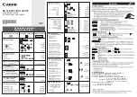
KS-1200TS
Brand: Canon Pages: 3

Calculator Keypad
Brand: Hama Pages: 12

Ultra Measure Master
Brand: Calculated Industries Pages: 64

KCA-R2FMA
Brand: Kenwood Pages: 36

KCA-R30FM
Brand: Kenwood Pages: 24

EL-2901C
Brand: Sharp Pages: 11

EL-2902C
Brand: Sharp Pages: 16

EL-2901C
Brand: Sharp Pages: 26

EL-2631L
Brand: Sharp Pages: 32

EL-2901PIII
Brand: Sharp Pages: 44

EL-2902E
Brand: Sharp Pages: 68

EL-2901RH
Brand: Sharp Pages: 112

EL-2901RC
Brand: Sharp Pages: 112

1511214
Brand: Nextech Pages: 2

6518202
Brand: Orbyx Electronics Pages: 1

"Bureau BSB 108A"
Brand: Hama Pages: 26

DH93RF
Brand: RCA Pages: 8

32SII
Brand: HP Pages: 376


