


IntelliVue Telemetry System Infrastructure
Installation and Service Guide
Part Number: M3185-91934
Printed in the U.S.A.
June, 2007
Second Edition
*M3185-91934*
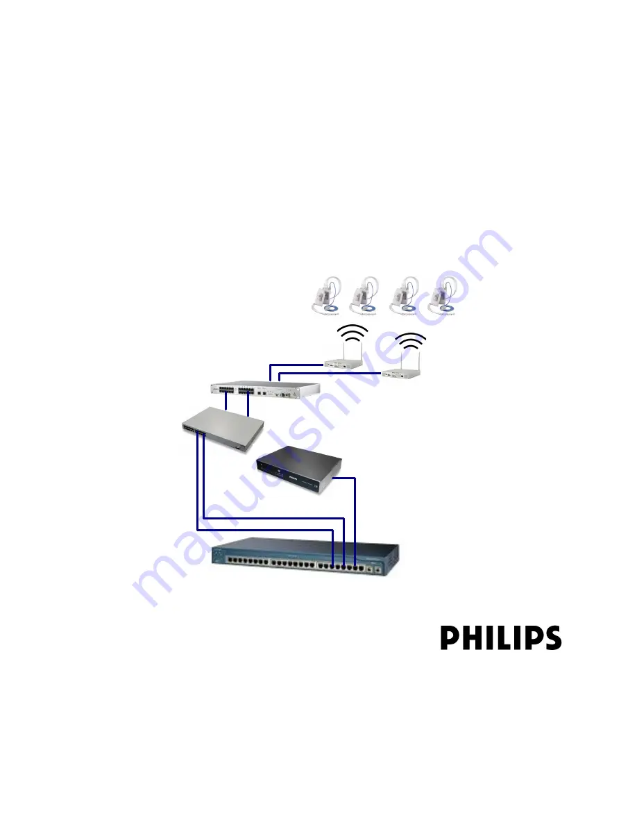
ICN Network Switch
Access Point Controller
ITS Synchronization Unit
ITS Power over Ethernet Unit
1.4/2.4 GHz Access Points
Patient-worn Transceivers
Summary of Contents for IntelliVue Telemetry System Infrastructure
Page 8: ...viii Contents ...
Page 14: ...xiv About This Guide ...
Page 100: ...3 22 Chapter 3 Installing and Configuring the ITS Figure 3 10 APC Filter Configuration Screen ...
Page 162: ...5 12 Chapter 5 Troubleshooting and Testing ...
Page 168: ...A 6 Chapter A Installing Multiple ITSs at a Single Hospital Site ...
Page 180: ...Index 8 Index ...


