background image

TABLE OF CONTENTS   


Page 

Version 1.0 

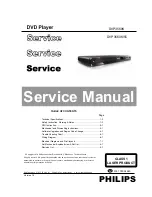
Service Manual 

. Technical Specifications…………....………………………..............1-2 

. Safety Instruction, Warning & Notes….……………………....….....1-3

. Mechanical and Dismantling Instructions…………........................3-1
. Software Upgrades and Region Code Change.............................

.

4-1

. Trouble Shooting Chart………………………………………………

.

5-1

. Wiring Diagram………………………………………..………..….….6-1 
. Electrical Diagrams and Print-layouts..….…………………....….…7-1     
. Set Mechanical Exploded view & Part list.…………………..….….8-1 

©Copyright 2010 Philips Consumer Electronics B.V. Eindhoven, The Netherlands 

All rights reserved. No part of this publication may be reproduced, stored in aretrieval system or 
transmitted, in any form or by any means, electronic, mechanical, photocopying, or otherwise 
without the prior permission of Philips. 

CLASS 1 

LASER PRODUCT

PHILIPS

GB

Published by SL  - 952   BU AVM      Printed in The Netherlands      Subject to modification

DVP3560K

DVP3560K/55

. DFU Instruction..............................................................................2-1

. Revision List..................................................................................9-1

3141 785 34640

Summary of Contents for DVP3560K

Page 1: ...xploded view Part list 8 1 Copyright 2010 Philips Consumer Electronics B V Eindhoven The Netherlands All rights reserved No part of this publication may be reproduced stored in aretrieval system or transmitted in any form or by any means electronic mechanical photocopying or otherwise without the prior permission of Philips CLASS 1 LASER PRODUCT PHILIPS GB Published by SL 952 BU AVM Printed in The...

Page 2: ...D Longitud de onda 658 nm DVD 790 nm CD Potencia de salida 7 0 mW DVD 10 0 mW VCD CD Divergencia de haz 60 grados VSHFLÀFDFLRQHV Nota DV HVSHFLÀFDFLRQHV HO GLVHxR TXHGDQ VXMHWRV D PRGLÀFDFLRQHV VLQ SUHYLR DYLVR USB Compatibilidad USB 2 0 de alta velocidad Clases UMS clase de almacenamiento masivo USB Video Sistema de señal PAL NTSC Salida de video compuesto 1 Vpp 75 ohmios Salida de video por comp...

Page 3: ... wire between the two pins of the mains plug 2 Set the mains switch the on position keep the mains cord unplug 3 Measure the resistance value between the mains plug and the front panel controls and chassis bottom 4 Repair or correct unit when the resistance measurement is less than 1M 5 Verify this before you return the unit to the customer user ref UL standard no 1492 6 Switch the unit off and re...

Page 4: ...ch copper tracks and or components in this unshielded primary area when you service the player Service personnel must take precautions to prevent touching this area or components in this area A lighting stroke and a stripe marked printing on the printed wiring board indicate the primary side of the power supply Never replace modules or components while the unit is on 2 Laser The use of optical ins...

Page 5: ...ch off un used equipment or reduce heat x Mix of lead free solder alloy parts with leaded solder alloy parts is possible but PHILIPS recommends strongly to avoid mixed solder alloy types leaded and lead free If one cannot avoid clean carefully the solder joint from old solder alloy and re solder with new solder alloy SAC305 x Use only original spare parts listed in the Service Manuals Not listed s...

Page 6: ...Register your product and get support at www philips com welcome DVP3560K DVD PLAYER DVP3560K 1 Y Pb Pr AUDIO OUT HDMI OUT HDMI 2 1 QSG for DVP3560K 55 ...

Page 7: ...2009 Koninklijke Philips N V All rights reserved DVP3560K_55_QSG_V1 0 DVD PLAYER DVP3560K 2 1 TV OUT AUDIO OUT 2 2 ...

Page 8: ... retrocede rápidamente Avanza o retrocede lentamente e BACK Regresa al menú de pantalla anterior f Pasa al título capítulo o pista anterior o siguiente g Pasa al modo de USB h Botones numéricos Selecciona la reproducción de un elemento i SUBTITLE Selecciona el idioma de los subtítulos en un disco Permite acceder al menú de copia y eliminación de archivos de audio USB j ZOOM Ajusta el formato de la...

Page 9: ...the Top Cover Figure 1 Figure 1 Step2 If it is necessary to dismantle Loader or Front Panel the Front door should be removed first Figure 2 Note Make sure to operate gently otherwise the guider would be damaged Figure 2 3 1 Please kindly note that dismantle the front door assembly carefully to avoid damage tray and the front door Detailed information please refer to the model set ...

Page 10: ...ote Make sure to operate gently otherwise the guider would be damaged Figure 3 Step4 Dismantling Front Panel disconnect the connectors XP80 XP7 XP476 need release 3 snaps of Front Panel 2 snaps of bottom cabinet then gently pull the Panel out from the set Figure 4 Figure 6 Figure 4 3 2 Detailed information please refer to the model set XP2 XP3 XP80 XP4 XP7 XP1 XP476 ...

Page 11: ...p6 Dismantling Main Board first disconnect the connector XP1 and then remove 4 screws Figure 6 Step7 Remove the 4 screws on Power Board to dismantle the Power Board Figure 6 Step5 Dismantling Loader disconnect the 3 connectors XP2 XP3 XP4 aiming in the below figure and remove 1 screw that connects the loader and the bottom cabinet Figure 5 ...

Page 12: ... A Upgrade software via CDR B Upgrade software via USB Flash Drive 1 Create the correct software file onto the USB flash drive 2 Power on the set and keep no disc then insert it to the USB jack of the front panel 3 When the DVD player switchs to the USB state automatically pls follow the instructions on the TV screen to confrim the upgrade operation 1 Power on the set and open the tray then press ...

Page 13: ...OCUS_PWM signals 2 If there are F F T and T signals output from U2 Check Replace the loader Yes Yes No Go Check whether laser voltage 1 9V for CD 2 4V for DVD on L9 and L10 Check the FFC connection between 24P and the loader 1 Whether voltage on pin 15of U20 varies between 0 and 3 3V 3 3V for CD and 0V for DVD 2 Whether peripheral components are eroded or badly soldered Trouble shooting chart Moto...

Page 14: ...upply on the power board is normal Check Correct connection Whether the connection to K303 is broken Correct the connection Replace U20 No No Yes Yes Check if the XS301 on the front board to XP5 on the decoder board is in good contact Whether there is 0V and 3 3V voltage difference on Pin 39 PCON of U20 Trouble shooting chart ...

Page 15: ...ck whether U20 are eroded All output voltages on the power board is 0V or deviated Check whether there is 300V on C1 or C2 Check whether 100KHz oscillating signal on Pin6 of U20 Check if 5V and 12V are short Check whether the components in the short circuit voltage are defected or eroded Yes Yes Yes Yes U1 PIN 3 RC waveform Trouble shooting chart Check whether F1 is blown ...

Page 16: ...C connection between 24P and the loader Check U20 and peripheral components Re solder or replace the defective parts Check the connection between U20 Correct connection Replace U20 or loader Yes Check whether there is laser voltage 1 9V for CD and 2 4V for DVD on L9 and L10 Check if there is RFO signal on pin17 of XP2 The normal RFO signal is a clear reticulated wave Trouble shooting chart Check U...

Page 17: ...heral components Check whether there is voltage variance on pin 17 of U20 check if bad solder exist on U20 and peripheral components Replace the bad spare parts Check whether pins of U20 and peripheral components are badly soldered defected Check Q5 Q7 whether in good condition Yes Yes Yes Go Correct connection Change U20 or the loader No Yes Check laser voltage 2 4V output on L10 if pin10 of U20 ...

Page 18: ...k the U20 s pin 36 37 38 arrive the XP5 connect condition Correct connection Replace U301 or LED Yes Yes Yes No Check VCC 5v voltage on the power and front board Check there are STB SDA and SCK signals on XS301 on the front board 1 Check whether bad solder exists on U301 and pins of LED 2 Check whether the circuit connected to K302 K303 and K301 is broken 3 Check whether R300 R301 and R302 are ope...

Page 19: ...k whether the muting transistor Q48 Q50 are normal Checking the U12 leads the feet has no to break to open Correct connection Replace R76 CE38 C152 Check the voltage on pin3 or pin5 of U12 is OK Should be 2 5 3 1V Check whether the U1 or U12 powersupply normal No Yes Check the power supply voltages 12V to the operation amplifying Q3 is normal Yes Check U12 Replace U20 No Yes Trouble shooting chart...

Page 20: ...oder board are normal Check Y2 R20 R27 C22 and C23 Check other of power supply electric circuit Correct the connection Check whether the video filter network circuit is normal Yes Yes No No No Check whether the 27MHz output signal Trouble shooting chart Change U20 Yes No Check if the video signals on Pin 98 100 101 102 of U1 are normal ...

Page 21: ... an oscilloscope to check if there is output waveform from the first pin IR of the remote censor after pressing button on the remote control REM301 PIN1 RC waveform Check if there is IR signal on pin 33 of U20 Check if the power supply voltage to the remote censor is normal Go No No No Yes Yes Yes Correct connection Yes Change U20 IR waveform Trouble shooting chart ...

Page 22: ...oscillator Y2 and peripheral components are defected or eroded No No No Yes Yes Yes 27Mhz waveform Trouble shooting chart Check whether all the voltages from the power board to the decoder board are normal CVBS R21 point waveform Check if there is 128MHz signal output on R67 Check whether short circuit or bad solder on U4 U5ˈ U8ˈ U7 SDRAM R67 DCLK waveform Check U20 No No Reconnect the component i...

Page 23: ...RS ARF SPDIF AVCM VSTB AUDIO_MUTE AKIN1 AUDIO_ALS GPIO12 115 114 110 109 105 ALF ALS GPIO21 TRCLOSE GPIO20 GPIO19 GPO14 96 VSDA AR 111 113 AL AR AL SP S LIMIT GND SL SL GND POWER K LED LED ASA F8829 SANYO DV38 1 Y 10PIN 2 0 Pb Pr R 1 LED KEY LEDˇET6202 POWER SUPPLY 24 1 5 1 5 MAIN BOARD MP 1 1 6 DVD LOADER 5PIN 2 0 6PIN 2 0 5PIN 2 5 24PIN 0 5 5PIN 2 5 CVBS 10 XP1 XS201 10PIN 2 0 XS301 XP5 XP3 XP4 ...

Page 24: ...00 ohm R315 100 ohm R317 33R R317 33R D302 1N4148 D302 1N4148 C301 100P C301 100P CE301 47uF CE301 47uF R305 4K7 R305 4K7 C305 100p C305 100p R300 100 R300 100 K302 play pause K302 play pause XS302 CON4 2 0 XS302 CON4 2 0 1 2 3 4 C315 47p C315 47p R306 51K R306 51K C307 100p C307 100p R319 0 ohm R319 0 ohm R314 0R NC R314 0R NC R310 1K R310 1K R311 1K R311 1K C302 100P C302 100P C308 100p C308 100...

Page 25: ...A B B C C D D E E 1 1 2 2 3 3 4 4 SWITCH BOARD C319 47p C319 47p C317 47p C317 47p C318 47p C318 47p XP1 CON4 2 0 XP1 CON4 2 0 1 2 3 4 LED3 LED3 K303 POWER K303 POWER Switch Board Circuit Diagram 7 2 7 2 ...

Page 26: ... INPUT 1 2 3 C208 100p R202 22K L201 500Z 47 USB003 XX2 USB P600 USB 1 2 3 4 5 6 C203 1000p R206 20K R209 680 CE200 22uF C210 2 2uF U200A NJM4558 3 2 1 8 4 U200B NJM4558 5 6 7 8 4 C206 47p R205 180K R211 100K R210 150 R203 22K R208 1K R200 10K L202 500Z C201 0 1u L200 500Z C205 47p CE201 22uF C211 2 2uF R201 5 6K R207 100K 8PIN 2 0mm XP601 1 2 3 4 5 6 7 C204 100p C209 2 2uF OK Board USB Board Elec...

Page 27: ... C513 0 1uF 63V C507 2200uF 10V C507 2200uF 10V U502 PC123X92 U502 PC123X92 1 2 4 3 U1 TNY177PN U1 TNY177PN S 8 EN UV 1 S 5 S 6 Drain 4 S 7 NC 3 BP M 2 R507 1 6W11 3k 1 R507 1 6W11 3k 1 RV501 10K471 RV501 10K471 C509 10uF 16V C509 10uF 16V FB501 FB FB501 FB CX501 0 1uF 275Vac CX501 0 1uF 275Vac T501 T501 10 11 1 4 6 8 2 5 9 7 3 C504 152 1KV C504 152 1KV C512 10uF 50V C512 10uF 50V D509 SR360 D509 ...

Page 28: ...K 1 R17 3 3K R17 3 3K C109 0 1uF C109 0 1uF R6 4 7 0603 R6 4 7 0603 CE5 47uF 16V CE5 47uF 16V C25 NC 0 1UF C25 NC 0 1UF C44 NC 47pF C44 NC 47pF C111 0 1uF C111 0 1uF C43 100pF C43 100pF R26 1K R26 1K R12 4 7K R12 4 7K R99 1K R99 1K Q21 2N3904 Q21 2N3904 C77 1uF C77 1uF R48 1R 1W R48 1R 1W Q22 2N3904 Q22 2N3904 R58 2 2K R58 2 2K R97 0R 5 1K 1 R97 0R 5 1K 1 C12 0 1uF C12 0 1uF CE23 47uF 6 3V CE23 47...

Page 29: ...MD0 5 TOP TOP XP2 SMD0 5 TOP 24 23 22 21 20 19 18 17 16 15 14 13 12 11 10 9 8 7 6 5 4 3 2 1 25 26 27 28 C35 0 01uF C35 0 01uF C80 4 7uF C80 4 7uF R4 2 5K 1 R4 2 5K 1 R1 15K NC R1 15K NC R101 NC 4 7K R101 NC 4 7K C18 0 1uF C18 0 1uF C38 330pF C38 330pF R20 100K R20 100K TP8 TP8 C19 0 1uF C19 0 1uF 4PIN 2 0mm XP7 4PIN 2 0mm XP7 1 2 3 4 R54 10K R54 10K R31 180 R31 180 R21 0 R21 0 C93 10uF 10V C93 10u...

Page 30: ...9 NC 15K R132 NC 68 R132 NC 68 C97 0 1uF C97 0 1uF R204 0 R204 0 R130 NC 3 3K R130 NC 3 3K R131 NC 10K R131 NC 10K Q26 NC 2N3904 Q26 NC 2N3904 R74 10K R74 10K C51 NC 5P C51 NC 5P C99 0 1uF C99 0 1uF R72 10K R72 10K R66 10K R66 10K U4 ESMT M12L64164A N C U4 ESMT M12L64164A N C VCC 1 DQ0 2 DQ1 4 VSSQ 12 DQ2 5 DQ3 7 VCCQ 9 DQ4 8 DQ5 10 VSSQ 46 DQ6 11 DQ7 13 DQML 15 WE 16 CAS 17 RAS 18 CS 19 A11 35 A1...

Page 31: ... L11 0R 1 8uH L11 0R 1 8uH C50 100pF C50 100pF R77 75 1 R77 75 1 R71 75 1 R71 75 1 47 RCA150 XX1 RCA P1 RCA VIDEO OUT 47 RCA150 XX1 RCA P1 RCA VIDEO OUT 1 2 3 4 5 6 C53 100pF C53 100pF C59 47pF C59 47pF CE16 470uF 6 3V NC CE16 470uF 6 3V NC R64 75 1 R64 75 1 D8 D8 2 1 D5 D5 2 1 U11 PESD3V3L5UY NA U11 PESD3V3L5UY NA 1 2 3 4 5 6 C52 100pF C52 100pF C56 47pF C56 47pF L13 0R 1 8uH L13 0R 1 8uH C58 47p...

Page 32: ...3 0 1uF R90 10K 1 R90 10K 1 R137 3 3K R137 3 3K C62 3300pF C62 3300pF CE28 47uF 16V NC CE28 47uF 16V NC C70 NC 1000pF C70 NC 1000pF R81 5 1K R81 5 1K Q13 9012 Q13 9012 C64 1000pF C64 1000pF CE21 10uF 16v CE21 10uF 16v R93 100k R93 100k Q14 9012 Q14 9012 U6B NJM4558 OPA U6B NJM4558 OPA 5 6 7 8 4 R86 33K R86 33K R87 10K R87 10K C60 100pF C60 100pF C68 100pF C68 100pF C101 0 1uF C101 0 1uF R100 4 7K ...

Page 33: ... OFF PAGE CONNECTION Differential Signal No through hole length less than 5cm 100 ohm Impedance TMDS I F R165 47K R165 47K R106 0R R106 0R C113 0 1uF C113 0 1uF CE37 10uF 16V CE37 10uF 16V C104 0 1uF C104 0 1uF C105 0 1uF C105 0 1uF FB19 FB500R FB19 FB500R D50 1N4148 D50 1N4148 R103 0 R103 0 R105 1 5K R105 1 5K C106 0 1uF C106 0 1uF R201 27K R201 27K R104 1 5K R104 1 5K P3 HDMI_TYPE_A HDMI TYPE A ...

Page 34: ...Front Board Switch Board Print layout Bottom side 7 11 7 11 ...

Page 35: ...OK Board and USB Board Print layout Top and Bottom side 7 12 7 12 ...

Page 36: ...Power Board Print layout Bottom side 7 13 7 13 ...

Page 37: ...Main Board Print layout Top side 7 14 7 14 ...

Page 38: ...Main Board Print layout Bottom side 7 15 7 15 ...

Page 39: ...8 1 Exploded view for DVP3560K 55 It is a general mechanical exploded view for DVP3560K 55 pls refer to the model set for detailed information ASSY1 includes components 1 3 4 5 21 ...

Page 40: ...510001168 24PIN HS 1 Q13 996510009670 TRANSISTOR SMT 3CG9012M 1 XP3 996510004063 CABLE PH 5Y PH 5Y L 130MM 1 Q14 996510009670 TRANSISTOR SMT 3CG9012M 1 XP4 996510021448 6PIN HS 1 Q15 996510009669 SMD TRANSISTOR MMBT3904LT1 NPN 1 XP601 996510020962 7PIN CABLE WITH SHIELD XP7 1 Q16 996510009671 PNP TRANSISTOR 1 XS301 996510001530 CABLE 10P HS 1 Q17 996510009671 PNP TRANSISTOR 1 Q2 996510009669 SMD T...

Page 41: ...REVISION LIST Version 1 0 Initial release for DVP3560K 55 9 1 ...

Reviews: