


NewFEIMAS
Refer to Revision Record on page 2.
T.Anzai
Nov.20, 2008
K.Okada
Rev
04
03
PAGE
1
/
138
PFU LIMITED
P1PA03334-B30X/6
Refer to Revision Record on page 2.
T.Anzai
July 7, 2008
K.Okada
Refer to Revision Record on page 2.
K.Oakda
K.Okada
DESCRIPTION
CHECK
DATE
T.Anzai
APPR.
K.Okada
K.Okada
Aug.19, 2005
DESIG
N
DESIG
.
CUST.
I.Fujioka
I.Fujioka
T.Anzai
CHECK
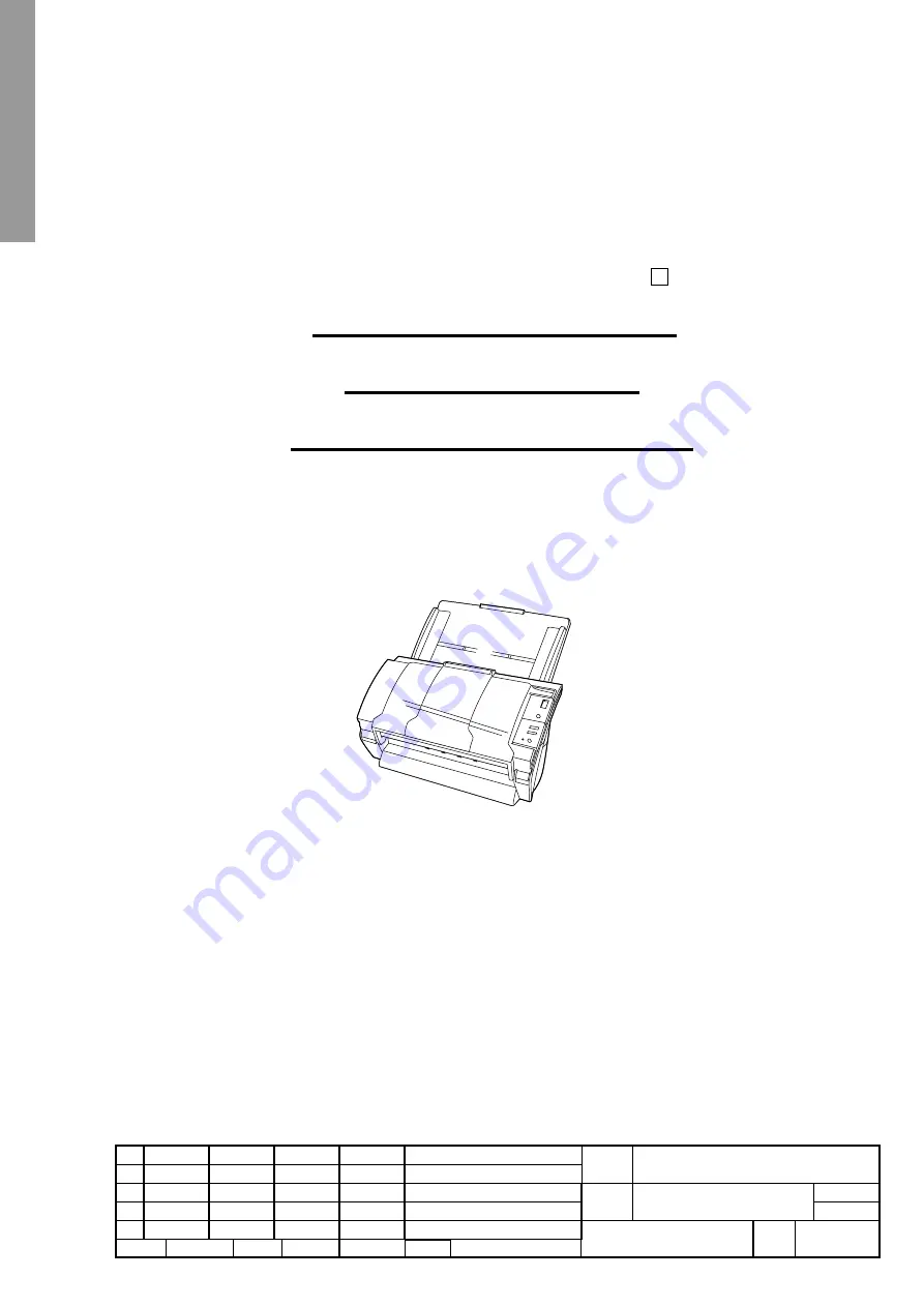
fi-5530C/fi-5530C2
IMAGE SCANNER
MAINTENANCE MANUAL
APPR.
TITLE
DRAW.
No.
Feb.23 2007
05
03
fi-5530C/fi-5530C2
Image Scanner
Maintenance Manual


