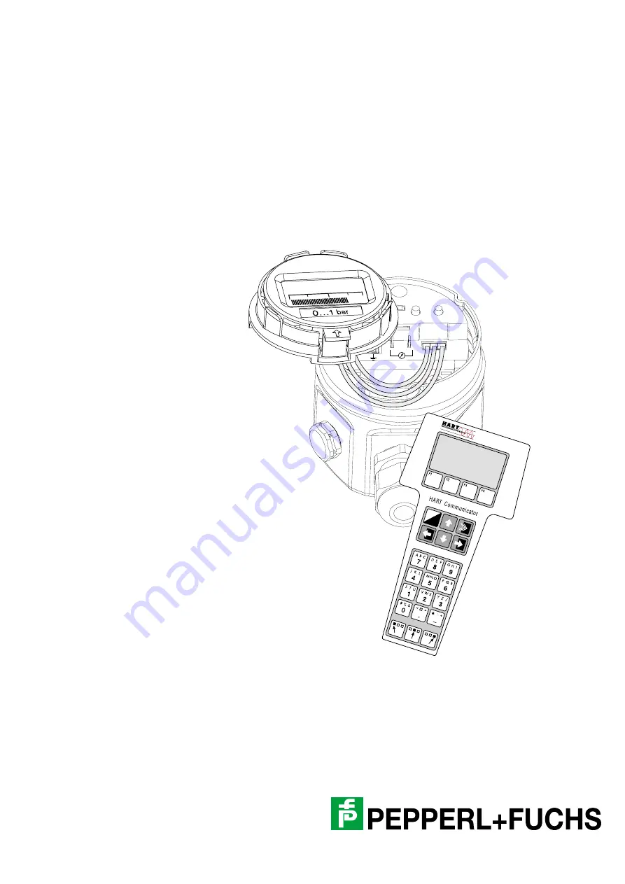
background image

1

2

+

3

Zero

Damping

on

off

Span

Display

0,753

I

O

BA 201O/98/en/07.01
Software version 1.0
52011571

Barcon Pressure Transmitter

Barcon PPC (HART)
Barcon LHC (HART)

Operating instructions

Summary of Contents for Barcon LHC

Page 1: ...1 2 3 Zero Damping on off Span Display 0 753 I O BA 201O 98 en 07 01 Software version 1 0 52011571 Barcon Pressure Transmitter Barcon PPC HART Barcon LHC HART Operating instructions ...

Page 2: ... of the Electrical Industry as published by the Central Association of the Elektrotechnik und Elektroindustrie ZVEI e V including the supplementary clause Extended reservation of title We at Pepperl Fuchs recognise a duty to make a contribution to the future For this reason this printed matter is produced on paper bleached without the use of chlorine ...

Page 3: ...al operation with digital display Remote operation via HART protocol Operation Function of the display Sect 3 2 Position and function of the operating elements on the electronic insert Sect 3 3 Commissioning on site Sect 4 1 Operation with PACTware Sect 3 4 with Universal HART Communicator Sect 3 5 Commissioning with remote communication Sect 4 2 ...

Page 4: ...C PPC HART Software history 4 Date of Issue 25 10 2001 Software history Software version Valid operating instructions BA Device and Software No Software revision Changes in operating instructions 1 0 07 01 8010 ...

Page 5: ...nd function of the operating elements on the electronic insert 22 3 4 Operation using PACTware 23 3 5 Operating with the HART protocol via universal HART communicator 24 4 Commissioning 25 4 1 On site commissioning 25 4 2 Commissioning and operation using communication 26 4 3 Locking unlocking operation 28 4 4 Information on the measuring point 29 5 Diagnosis and troubleshooting 30 5 1 Diagnosis o...

Page 6: ...e manual Explosion hazardous area The measuring system used in the explosion hazardous area must comply with all existing national standards The instrument can be supplied with the following certificates as listed in the table The certificates are designated by the last letters of the order code on the nameplate see table below Ensure that technical personnel are sufficiently trained All measureme...

Page 7: ...an explosion hazardous area Explosion hazardous area Symbol used in drawings to indicate explosion hazardous areas Devices located in and wiring entering areas with the designation explosion hazardous areas must conform with the stated type of protection Safe area non explosion hazardous area Symbol used in drawings to indicate if necessary non explosion hazardous areas Devices located in safe are...

Page 8: ...ssure deflects the separating diaphragm with a filling liquid transmitting the pressure to a resistance bridge The bridge output voltage which is proportional to pressure is then measured and processed Fig 1 1 Sensor construction Measuring system The complete measuring system consists of Barcon pressure transmitter with 4 mA 20 mA signal output with superposed digital signal HART communication and...

Page 9: ... sight glass glass Ex i lid with lid lock and sight glass glass lid with sight glass polycarbonate display module complete with retaining ring retaining ring separate profile seal 64 2 x 72 7 x 5 set 5 pieces Mechanical design of Barcon with stainless steel housing measuring cells measuring range 0 bar 0 1 bar 0 bar 0 4 bar 0 bar 1 bar 0 bar 4 bar 0 bar 10 bar 0 bar 40 bar 0 1 bar 0 1 bar 0 4 bar ...

Page 10: ... x 3 0 central mount metal PAL clamp inside PAL clamp outside PAL cable safety loop for cover with certificate EEx d M20 x 1 5 Mechanical design of Barcon with aluminium housing NPT M20 x 1 5 G M12 x 1 plug Harting plug cable entry measuring cells measuring range 0 bar 0 1 bar 0 bar 0 4 bar 0 bar 1 bar 0 bar 4 bar 0 bar 10 bar 0 bar 40 bar 0 1 bar 0 1 bar 0 4 bar 0 4 bar 1bar 1 bar 1bar 4 bar 1bar...

Page 11: ...xternal NPT external NPT internal PF external PT external M20 x 1 5 external seal FKM Viton exchangeable thread 1 4435 PTFE Hastelloy C two piece FKM FKM NBR EPDM FFKM Kalrez FFKM Chemraz 1 O ring 26 7 x 1 78 1 fof oxygene only thread G external M20 x 1 5 external NPT external NPT internal NPT internal 11 4 mm internal PT external G external G internal G external 11 4 mm internal PF external G ext...

Page 12: ...nd cell welded together Process connection LHC M20 DIN 11851 DN 50 DIN 11851 DN 40 DIN 11864 1 A DN 40 DIN 11864 1 A DN 50 SMS 1 SMS 2 Clamp 2 Varivent 68 mm DRD D 65 mm APV Inline PN 40 G2 2 NPT process seals of the membrane O rings 26 7 x 1 78 FKM FFKM Kalrez FKM EPM NBR 1 threaded boss 1 4435 measuring cell with sanitary couplings 1 4435 process seal inside process seal inside process seal insi...

Page 13: ...he application Measurement in gases Mount the shut off valve above the tapping point so that condensate can run back into the process Fig 2 1 Mounting on a shut off valve for measuring gases Measurement in steam Mount with a pigtail above the tapping point The pigtail reduces the temperature in front of the diaphragm to almost ambient temperature Before start up the pigtail must be filled with wat...

Page 14: ...ons with flush mounted diaphragm or with adapter and internal diaphragm The adapter can be screwed on or welded in A gasket is enclosed according to the material used and version Fig 2 4 PPC M10 with flush mounted diaphragm 3 3 4 3 3 G G G Ø 26 4 Ø 26 4 Ø 26 4 27 21 3 50 14 15 2 5 22 21 21 19 4 17 17 17 G external with O ring Viton seal O ring 14 x 1 78 Viton or NBR G external Viton seal DIN 3852 ...

Page 15: ...ting in order to protect the diaphragm The diaphragm of the diaphragm seal of the Barcon must not be dented or cleaned with pointed or hard objects The diaphragm seal and the pressure sensor together form a closed and calibrated system which is filled with filling fluid through a hole in the upper part of the sensor The following rules should be observed This hole is sealed and is not to be opened...

Page 16: ...x 10 mbar 0 15 psi Fig 2 7 Mounting with temperature spacers Mounting with capillary tubing To protect from high temperature moisture or vibration or where the mounting point is not easily accessible the housing of the Barcon can be mounted with a capillary tube to one side of the measuring point A bracket for mounting on a wall or pipe is available for this Fig 2 8 Mounting with capillary tubing ...

Page 17: ...with bracket on a wall Values in brackets apply to instruments with a raised cover PPC M10 wall and pipe mounting with bracket Fig 2 10 left Mounting with bracket on a vertical pipe righ Mounting with bracket on a wall Values in brackets apply to instruments with a raised cover 159 98 118 32 94 3 176 60 3 81 111 32 97 117 70 60 3 6 184 5 60 3 81 119 5 26 113 133 70 60 3 6 167 5 114 134 26 102 5 3 ...

Page 18: ...play In addition Push up the latch with the arrow until the grip of the retaining ring is audibly released Loosen the retainer ring carefully to prevent the display cable from breaking The plug of the display can remain plugged in Insert the cable through the cable entry Connect the cable wires as shown in the connection diagram Where appropriate replace the retainer ring with digital display The ...

Page 19: ... grounding terminal of the housing and not to Terminal 3 see connecting diagrams Fig 2 13 Connection Plug Plug assignment Terminal Function Wire colour code Harting plug 1 2 8 PE Blue BL Brown BN Green Yellow GNYE Plug M12 x 1 PE Red RD Black BK Green GN Note 1 2 3 1 2 3 Zero Damping on off Span Display Test 4 mA 20 mA Always connect the screening or ground cable if present to the internal ground ...

Page 20: ... The handheld terminal can be connected anywhere along the 4 mA 20 mA line Connecting the HART Modem for operating with PACTware The HART modem connects the Barcon with a HART protocol to the RS 232 C serial interface of a personal computer This enables the Barcon to be remotely operated with operating program PACTware Fig 2 15 The HART modem can be connected anywhere along the 4 mA 20 mA line 4 m...

Page 21: ...o order an digital display at a later date then please observe the instructions in chapter 6 3 Mounting the digital display Removing the display Push up the latch with the arrow until the grip of the retaining ring on the electronic insert is heard to click Loosen the retainer ring and lift off carefully to prevent the display cable from breaking For reading the display during operation plug the d...

Page 22: ...cel 0 bar 1 bar 0 753 0 753 0 250 Z S Display in measurement mode ó ì ö ú Display in calibration mode ø 1 2 3 Zero Damping on off Span Display Damping switch ó Key for zero point calibration ì Key for measuring span calibration Connection terminals for measuring the signal current No Operating element Function Damping switch Switch position off Damping 0 s Switch position on Damping 2 s This switc...

Page 23: ...ted and operated The appropriate server e g HART must be activated A description of the PACTware operating program is found in the operating manual Display and operating program The advanced functions of the Barcon can be accessed in this operating mode in the menu The calibrating parameters are entered in the appropriate fields Fig 3 4 Menu of instrument data in PACTware ...

Page 24: ...nicator handheld terminal Connecting the handheld terminal is described in chapter 2 The procedure for commissioning the measuring point with the Universal HART Communicator handheld terminal is described in chapter 4 F1 F4 F2 F3 Barcon LIC0001 Online 2 PV 20 mbar 1 Wähle Gruppe HELP F1 F4 F2 F3 Barcon LIC0001 Wähle Gruppe 2 Transmitter Information 3 Sensordaten 4 Service 5 Kommunikaton 1 Grundabg...

Page 25: ...Switch position on Damping 2 s Fig 4 1 Position of the damping switch Fig 4 2 Position of keys for calibrating zero point and measuring span Zero point adjustment Zero point calibration is carried out using the key for zero point adjustment Zero Carry out the measuring span adjustment as follows Enter exactly the pressure for the lower range value Press the Zero key twice The acting pressure is ad...

Page 26: ... must be set to on Values for damping between 0 s and 40 s can be selected using the handheld terminal Selecting the pressure units Selecting the pressure units determines in which units the pressure specific parameters are to be shown The pressure units available are given in the table below After selecting new pressure units all information on the pressure are converted into the new units e g 0 ...

Page 27: ...ing known pressure for zero point V0H1 Setting 4 mA e g 0 psi Enter 2 Entering known pressure for span V0H2 Setting 20 mA e g 14 5 psi Enter 1 2 3 Zero Damping on Span Display off I O Enter zero point and measuring span No reference pressure Para Moving through the menus Entry Main group Basic settings 1 Adopting the acting pressure for the zero point V0H3 Confirming 4 mA automatically e g 0 psi E...

Page 28: ...nlocking operation After calibrating or entering all parameters the operation can be locked by entering a three figure code other than 130 This blocks all fields and functions except V9H9 Locking Locking is released by entering 130 Para Moving through the menus Entry Main group Basic settings 1 Selecting output on error V0H8 Selecting fail safe e g MAX Enter para Moving through the menus Entry Mai...

Page 29: ...sensor units in V0H9 selectable V7H7 Upper measurement limit of sensor units in V0H9 selectable Information on transmitter V2H2 8010 Software number V2H7 Sensor data No Number of entry in the sensor table 1 10 Please remove from sensor pass V2H8 Sensor data value Entry in sensor table contains all sensor specific data Please remove from sensor pass Error response V2H0 Actual diagnostic code V2H1 L...

Page 30: ... 5 2 Current simulation Sollen die Funktion oder bestimmte Reaktionen von eingeschleiften Auswertegeräten überprüft werden kann ein Signalstrom unabhängig vom anliegenden Systemdruck simuliert werden Code Type Ursache und Beseitigung E 101 Error Sensor Table check sum error is shown e g when sensor parameters are being entered The error message disappears when the sensor parameters are entered cor...

Page 31: ...H8 H9 V0 5140 2380 731 2509 Sets 4 mA 0 0 0 0 0 0 Sets 20 mA V7H7 V7H7 V7H7 4 mA automat deleted deleted deleted 20 mA automat deleted Sets bias pressure 0 0 0 0 0 0 Bias pressure autom deleted Dampens output 0 0 0 0 0 0 Selects fail safe max max max Pressure unit bar V2 5140 2380 2509 731 Diagnos tic code 0 0 0 V3 V6 V7 5140 2380 2509 731 Simulatio n off Simulates current deleted Current min 4 mA...

Page 32: ...Replacement parts In the chapter 2 1 shows all replacement parts which can be ordered from Pepperl Fuchs When ordering replacement parts please note the following If parts given in the order code are to be replaced then ensure that the order code instrument designation on the nameplate is still applicable If the instrument designation on the nameplate has changed then a modified nameplate must als...

Page 33: ...f the display from the electronic insert Fig 6 1 left Loosening the retaining ring right Removing the display Mounting the display Insert the plug of the display in the jack in the electronic insert provided for this purpose and clip in Insert the pin on the retaining ring into the hole in the electronic insert provided for this purpose ó Firmly press down the retaining ring with the display onto ...

Page 34: ...ert All information on this is given in subsection Entering sensor parameters in this section After replacing the electronic insert the instrument must be recalibrated Information on adjustment is given in chapter 4 Commissioning If the existing Smart electronic insert is to be replaced with an analogue electronic insert then the information contained in BA 200O supplied with the analogue electron...

Page 35: ...rs are entered correctly V2H7 sensor data No V2H8 sensor data value 01 Word 16 sensor check sum 02 HI Word 16 sensor serial number 03 LO Word 16 sensor serial number 04 HI Word 16 lower measurement limit 05 LO Word 16 lower measurement limit 06 HI Word 16 upper measurement limit 07 LO Word 16 upper measurement limit 08 HI Word 16 sensor coefficient A0 09 LO Word 16 sensor coefficient A0 10 HI Word...

Page 36: ...nstructions on calibration see chapter 4 Commissioning 6 6 Changing the gasket The gasket in contact with the medium and inside the process connection of the Barcon PPC M20 can be replaced Except for the PTFE gasket all gaskets can thus be interchanged as required The different temperature limits should therefore be observed for individual materials Upper temperature limit according to specificati...

Page 37: ...n and power supply e g via transmitter power pack and operation via two keys on the instrument and a plug in display module handheld terminal PC with the PACTware operating program via HART modem Construction Standard SS housing for process connections see Seite 9 Signal transmission 4 mA 20 mA signal with superposed HART communications signal 2 wire Input Measured variables Absolute or gauge pres...

Page 38: ...or 10 C 60 C 14 F 140 F 0 2 x TD 0 2 for 40 C 10 C 40 F 14 F 60 C 85 C 140 F 185 F 0 4 x TD 0 4 Temperature coefficient maximum TK But not exceeding the error due to thermal effects for zero signal and span for 10 C 60 C 14 F 140 F 0 08 of nominal value 10 K for 40 C 10 C 40 F 14 F 60 C 85 C 140 F 185 F 0 1 of nominal value 10 K Vibration effects None 4 mm in path peak to peak 5 Hz 15 Hz 2 g 15 Hz...

Page 39: ...435 SS316L Seals see Section 6 6 FPM Viton FPM Viton grease free FPM Viton oil and grease free for oxygen EPDM Kalrez NBR DVGW version with NBR seal Mounting accessories Bracket for pipe and wall mounting 1 4301 SS 304 Filling fluid in diaphragm seals Silicone oil vegetable oil glycerine high temperature oil FLUOROLOBE grease free for oxygen Measuring cell Filling fluid PPC M20 LHC M20 PPC M10 LHC...

Page 40: ...al with O ring for welded nozzle 162 0 mm Diaphragm flush mounted G external 197 5 mm NPT external 197 5 mm NPT internal 184 5 mm PF external 195 5 mm PT external 197 5 mm M20 x 1 5 external 197 5 mm LHC M20 Dairy connections Threaded bosses Flanges Max height Triclamp 2 172 5 mm SMS 1 172 5 mm SMS 2 172 5 mm DIN 11851 DN 40 PN 40 172 5 mm DIN 11851 DN 50 PN 40 172 5 mm Varivent D 68 mm 172 5 mm D...

Page 41: ...m 255 0 mm DN 80 PN 10 40 Extension 50 mm 259 0 mm DN 50 PN 10 40 Extension 100 mm 255 0 mm DN 80 PN 10 40 Extension 100 mm 259 0 mm DN 50 PN 10 40 Extension 200 mm 255 0 mm DN 80 PN 10 40 Extension 200 mm 259 0 mm Flanges dimensions to ANSI B16 5 with sealing strip Form RF 1 400 600 lbs 250 5 mm 1 900 1500 lbs 254 5 mm 1 2500 lbs 254 5 mm 2 150 lbs 254 5 mm 2 300 lbs 257 5 mm 2 400 600 lbs 267 0 ...

Page 42: ...Transmitter information Diagnostic code Last diag nostic code 8010 Software No Sensor data No Sensor data value Reset 731 2380 V3 V6 V7 Sensor data Current display Off Simulation Simulates current Off Current output min 4 mA Low sensor calibration High sensor calibration Lower measure ment limit Upper measure ment limit Sensor pres sure V8 V9 Service Pressure before bias correction Locking 130 Unl...

Page 43: ...dous area G Gasket H HART protocol I Information on the measuring point L Locking M Measuring cell Measuring span adjustment Measuring system Metal sensor Mounting Mounting accessories Mounting bracket Mounting instructions Mounting the display N Notes on safety O On site commissioning Operating elements Operating matrix Operating principle Operation Output on error P PACTware R Reference pressure...

Page 44: ...Barcon LHC PPC HART Notes 44 Date of Issue 25 10 2001 ...

Page 45: ...Barcon LHC PPC HART Notes Date of Issue 25 10 2001 45 ...

Page 46: ...Barcon LHC PPC HART Notes 46 Date of Issue 25 10 2001 ...

Page 47: ...s of the Electrical Industry as published by the Central Association of the Elektrotechnik und Elektroindustrie ZVEI e V including the supplementary clause Extended reservation of title We at Pepperl Fuchs recognise a duty to make a contribution to the future For this reason this printed matter is produced on paper bleached without the use of chlorine ...

Page 48: ... of Application Worldwide Headquarters 01 23 42563 7 89 4 3 34 6 89 4 3 34 6 66 e mail pa info de pepperl fuchs com http www pepperl fuchs com USA Headquarters 466 7 88623 7 556 8 5 556 8 8463 e mail sales us pepperl fuchs com Asia Pacific Headquarters 2 5998 7 4 3 39 96 9 4 2 35 4 53 e mail sales sg pepperl fuchs com Service Area ÌÌ Ì ...

Reviews: