background image

Installation/Operation

CC3610 and CC3710 Series
Color Camera

C2914M-F (08/05)

Pelco Worldwide Headquarters • 3500 Pelco Way, Clovis, CA 93612-5699 USA • www.pelco.com

USA & Canada: Tel 800/289-9100 • FAX 800/289-9150

International: Tel: 1-559/292-1981 • FAX 1-559/348-1120

Summary of Contents for CC3610 series

Page 1: ...10 and CC3710 Series Color Camera C2914M F 08 05 Pelco Worldwide Headquarters 3500 Pelco Way Clovis CA 93612 5699 USA www pelco com USA Canada Tel 800 289 9100 FAX 800 289 9150 International Tel 1 559...

Page 2: ...ectra Genex Legacy Esprit and Camclosure are registered trademarks of Pelco Endura and ExSite are trademarks of Pelco DLP is a trademark of Texas Instruments Inc SuperHAD CCD is a trademark of the Son...

Page 3: ...ens Setup and Focus Procedures 13 Back Focus Adjustment 14 Switch Settings 15 Camera Synchronization 17 SPECIFICATIONS 18 WARRANTY AND RETURN INFORMATION 22 LIST OF ILLUSTRATIONS 1 Camera Layout 7 2 A...

Page 4: ...in any way such as when the power supply cord or plug is damaged liquid has been spilled or objects have fallen into the apparatus the apparatus has been exposed to rain or moisture the apparatus does...

Page 5: ...and the receiver Connect the equipment into an outlet on a circuit different from that to which the receiver is connected Consult the dealer or an experienced radio TV technician for help You may als...

Page 6: ...s Exview HAD CCD 0 4 lux at F1 2 PAL 110 240 VAC CC3710S 6 Standard resolution 330 TV lines SuperHAD CCD 0 6 lux at F1 2 NTSC 12 VDC 24 VAC CC3710S 6X Standard resolution 330 TV lines SuperHAD CCD 0 6...

Page 7: ...Screw the lens onto the lens mount Be careful to prevent dust from entering the space between the lens and the CCD element If necessary use clean compressed air to remove any foreign matter 3 Auto Ir...

Page 8: ...or tripod They are designed to accept standard photographic mounting bolts 1 4 inch UNC 20 The mounting bracket must be capable of supporting the weight of the camera and its lens NOTE Some installati...

Page 9: ...rly marked on the rear panel of the camera The green POWER LED on the rear panel indicates that power is connected Power low voltage cameras only from a UL Listed Class 2 isolated power supply Power c...

Page 10: ...ire Gauge 24 VAC 12 VDC AWG mm2 Feet Meters Feet Meters 24 0 25 224 68 56 17 22 0 35 356 108 89 27 20 0 5 567 172 141 42 18 1 902 274 225 68 16 1 5 1432 436 358 109 14 2 5 2285 696 571 174 12 4 3622 1...

Page 11: ...able and connectors according to Table C More information about wiring each pair of leads appears in the text below the table Then plug the auxiliary connector into the camera Figure 4 RJ45 10 Connect...

Page 12: ...ded twisted pair UTP wiring to equipment fitted with a suitable receiver Ensure that connection polarity is observed in relation to the connected twisted pair receiver To implement UTP you must use 5...

Page 13: ...far and view an image greater than 6 5 feet 2 m away 3 Focus the image with the back focus adjustment ring refer to the Back Focus Adjustment section 4 Set the lens focus as required Manual Iris Lens...

Page 14: ...assembly is as far away from the back of the lens as possible 3 Turn the back focus ring clockwise until focus is achieved 4 When the back focus adjustment is satisfactory tighten the locking screws...

Page 15: ...oose between the following settings ON Enables the Electronic Shutter Control mode OFF Default setting Disables the Electronic Shutter Control mode BLC Backlight Compensation Switch Setting 3 The BLC...

Page 16: ...of the power supply Set the camera synchroni zation mode to one of the following INT Disables line lock and cameras will synchronize internally Regardless of the DIP switch setting cameras switch to...

Page 17: ...people in communication when line locking cameras one person at the camera and another person at the monitor to observe the vertical roll and the effect of any adjustments made at the camera To line l...

Page 18: ...0 7 lux at F1 2 40 IRE AGC on Signal to Noise Ratio 50 dB Vertical Phase Adjustable 180 Automatic Gain Control On off switchable Electronic Shutter Control On off switchable Backlight Compensation On...

Page 19: ...VIRONMENTAL Operating Temperature 14 to 122 F 10 to 50 C Storage Temperature 14 to 158 F 10 to 70 C Operating Humidity 20 to 80 non condensing Storage Humidity 20 to 90 non condensing PHYSICAL Dimensi...

Page 20: ...20 Pelco Manual C2914M F 08 05...

Page 21: ...Pelco Manual C2914M F 08 05 21...
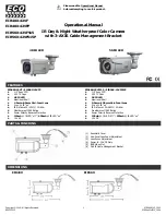
Page 22: ...ranty Pelco assumes no risk and shall be subject to no liability for damages or loss resulting from the specific use or application made of the Products Pelco s liability for any claim whether based o...

Page 23: ...Lens connector pin out changed C2914M B 09 04 Clarified instructions for UTP use C2914M C 11 04 Added UL warning for high voltage models C2914M D 11 04 Revised safety instructions C2914M E 12 04 Revis...

Page 24: ...anada Tel 800 289 9100 Fax 800 289 9150 International Tel 1 559 292 1981 Fax 1 559 348 1120 www pelco com www pelco com www pelco com www pelco com www pelco com ISO9001 9001 9001 9001 9001 United Sta...

Reviews: