background image

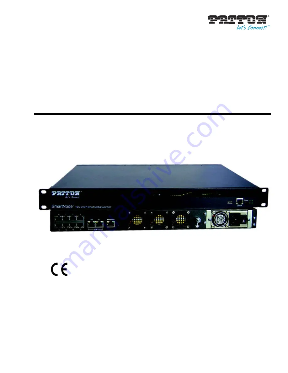
SmartNode™ 10100 Series

TDM+VoIP Smart Media Gateway

User Manual

Sales Office:


+1 (301) 975-1000

Technical Support:


+1 (301) 975-1007

E-mail:


[email protected]

www.patton.com

Part Number: 

07MSN10100-UM

Revised: 

April 30, 2013

Important

This is a Class A device and is not intended for use in a residential environment. 

Содержание SmartNode 10100 Series

Страница 1: ...ser Manual Sales Office 1 301 975 1000 Technical Support 1 301 975 1007 E mail support patton com www patton com Part Number 07MSN10100 UM Revised April 30 2013 Important This is a Class A device and...

Страница 2: ...f such license Patton Electronics warrants all SN10100 components to be free from defects and will at our option repair or replace the product should it fail within one year from the first date of the...

Страница 3: ...3 Summary Table of Contents 1 General Information 13 2 Hardware Installation 17 3 Initial Setup and Web Management 26 4 Contacting Patton 45 A Compliance Information 49 B Specifications 50...

Страница 4: ...0 Connecting the Management Interface 21 Connecting to a VoIP Network 21 Connecting to the PSTN 22 Connecting Power 23 Connecting to AC Power 23 Connecting to DC Power 24 Powering Down 25 3 Initial Se...

Страница 5: ...ion is Operating 38 Verifying the Application Path 39 Activating the Configuration 39 Verifying status 41 Configuring IP Interfaces 43 List of Parameters 44 4 Contacting Patton 45 Introduction 46 Cont...

Страница 6: ...6 Simultaneous Signaling Support 51 SmartNode CONTROL 51 OAM P 52 Operating Environment 52 Physical Characteristics 52 Electrical Characteristics 52...

Страница 7: ...e User 33 17 Navigation Menu Logout 34 18 Global Backups 34 19 Backups Create new database backup 35 20 Database Backup Message 35 21 Database Backup List 35 22 Download Database Backup 35 23 Upload D...

Страница 8: ...List of Tables 1 General conventions 12 2 SmartNode 10100 PSTN Ports and Voice Channels 15 3 SmartNode 10100 Height Requirements 19 4 DC Power Cables 25 5 Configuration Parameters for IP Interfaces 4...

Страница 9: ...tains the following chapters and appendices Chapter 1 on page 13 provides information about the SN10100 s features and capabilities Chapter 2 on page 17 provides hardware installation procedures Chapt...

Страница 10: ...ANT heading calls attention to important information The alert symbol and CAUTION heading indicate a potential haz ard Strictly follow the instructions to avoid property damage The shock hazard symbol...

Страница 11: ...LAN PSTN ports connections may have hazardous voltages present regardless of whether the device is powered ON or OFF PSTN relates to interfaces such as telephone lines FXS FXO DSL xDSL T1 E1 ISDN Voic...

Страница 12: ...ground yourself by touching the metal part of the chassis Table 1 General conventions Convention Meaning Garamond blue type Indicates a cross reference hyperlink that points to a figure graphic table...

Страница 13: ...13 Chapter 1 General Information Chapter contents SN10100 Overview 14 Features 14 SN10100 model codes 15...

Страница 14: ...s Just as flexibility in the selection and deployment of TDM links is a key requirement for service providers the need to support multiple signaling protocols across various carrier partners is just a...

Страница 15: ...ole in reducing energy costs with an average two thirds less power consumption than competing products of similar capacity Provisioning and Maintenance For network convergence efforts to contribute po...

Страница 16: ...00 Series User Manual 1 General Information SN10100 8E RUI 8 240 SN10100 8E 48 8 240 SN10100 8E R48 8 240 Table 2 SmartNode 10100 PSTN Ports and Voice Channels Model E1 T1 Interfaces DS3 Interfaces OC...

Страница 17: ...plies 18 Procedures 18 Mounting the SN10100 to a Rack 19 Connecting to the Console Serial Port 20 Connecting the Management Interface 21 Connecting to a VoIP Network 21 Connecting to the PSTN 22 Conne...

Страница 18: ...100 Quick Start guide Not included with the SN10100 No power cords are supplied for AC units Two DC power cables are included with DC units A 19 equipment rack You must use a standard 19 wide equipmen...

Страница 19: ...exhaust heat vents and the efficient heat dis sipation design there is no need to leave any physical vertical space above or below the placement of the SN10100 on the equipment rack The SN10100 is mou...

Страница 20: ...the SN10100 as shown in Figure 2 2 If your computer s serial port features a DB9 connector use the DB9 to RJ 45 adapter supplied with your SN10100 If your computer s serial port features a USB connec...

Страница 21: ...nagement port labeled Ethernet on the front of the SmartNode 10100 2 Log into the SmartNode using the specific credentials included on the Important Notice sheet that shipped with your unit The manage...

Страница 22: ...r end of the same CAT5 cable to the second Gigabit Ethernet switch Figure 5 Connecting to a VoIP network Connecting to the PSTN A SN10100 with 8 RJ48C type ports enables the connection to T1 E1 lines...

Страница 23: ...tions for information about power Connecting to AC Power on page 23 Connecting to DC Power on page 24 Powering Down on page 25 Connecting to AC Power The SN10100 AC model is furnished with two AC powe...

Страница 24: ...DC power cables To connect the SN10100 to DC power perform the following 1 Connect one DC cable supplied with the SN10100 as shown in Figure 8 to the DC outlet at the rear of the SN10100 2 Connect one...

Страница 25: ...bles Cable Type Voltage OV Ground 48V Yellow Black Black Yellow Red Black Red Black DO NOT TURN OFF the power to the SN10100 using the power switch located at the rear unless the Linux host has been p...

Страница 26: ...ting the Web Portal 30 Navigation and Information Panels 30 Knowing Your Location 31 Managing Users 32 Understanding User Access Levels 32 Viewing the User List 32 Creating a New User 33 Deleting a Us...

Страница 27: ...the following sections for more information Accessing the SmartNode via the Console Management Port on page 27 Accessing the SmartNode via the Ethernet Management Port on page 29 Accessing the SmartN...

Страница 28: ...following default gateway address to the network configuration file vi etc sysconfig network Example HOSTNAME SN005376 NETWORKING yes GATEWAY 192 168 200 1 Setting the IP address to DHCP 1 To change...

Страница 29: ...t Example DNS configuration file containing a DNS server generated by sbin dhclient script nameserver 4 2 2 2 Accessing the SmartNode via the Ethernet Management Port The SN10100 is shipped with the S...

Страница 30: ...g the Web Portal Effective use of the Web Portal requires a basic understanding of the physical elements of the tool how to access its various components and knowing your current location in the Web P...

Страница 31: ...this easy for you When you browse through the navigation panel your current selection is always indicated by a graphical highlight In addition the system configuration that you are using and the speci...

Страница 32: ...t any restrictions imposed Subsequent users can be created with the ability to read and write or just to read An integer value from 0 9 is assigned to each user Figure 12 SN10100 User Access Levels A...

Страница 33: ...er a Username and Password 4 Select a Read Privilege Level from 0 9 5 Select a Write Privilege Level from 0 9 6 Press Create to save your changes The User List window is displayed with the newly added...

Страница 34: ...out from the Web Portal select Logout from the navigation panel Figure 17 Navigation Menu Logout Managing the Database Backup After carrying out system modifications it is recommended that you backup...

Страница 35: ...e Backup List Figure 21 Database Backup List Downloading a Database Backup Once you have created a backup of your database it is recommended that you download it to store on an exter nal storage devic...

Страница 36: ...tion and how to configure IP interfaces Refer to the following sections for specified information Managing Applications on page 36 Activating the Configuration on page 39 Configuring IP Interfaces on...

Страница 37: ...on the Smart Media application server In addition at least one Smart Media unit must have been configured on the Smart Media application server so that you are able to connect to it When you first lo...

Страница 38: ...ions are as follows Verify the application s current path It is important that once the application has been set to run a path is displayed Verify the TDM interface If you are running a TDM applicatio...

Страница 39: ...3 Verify that the application path is displayed Verify that the target state is set to Run the current state dis plays Ready and the current HA state displays Active Figure 31 Application Status List...

Страница 40: ...on screen Figure 33 System List 3 Activate the configuration and enter a name for the system Under Activate Configuration Select a Con figuration on which to run the system Click Activate Note Make ce...

Страница 41: ...r database when you are done configuring at top of screen in blue Figure 35 Successful Activation Verifying status General and detailed status information about the applications that are run by one or...

Страница 42: ...l View Detailed View A more detailed description of each application can be viewed by following the appropriate link in the general window shown above The detailed status screen shown below lists the...

Страница 43: ...setting the following information IP Address Netmask Gateway To configure a VoIP0 or VoIP1 port 1 Select IP Interfaces from the navigation pane Figure 39 Menu IP Interfaces 2 Click Edit from the IP I...

Страница 44: ...s Click on the adapter Serial Number Reboot adapter It will take about 1 5 minutes to restart the unit List of Parameters The system will display the following notice describing steps to apply your ne...

Страница 45: ...rt Headquarters in the USA 46 Alternate Patton Support for Europe Middle East and Africa EMEA 46 Warranty Service and Returned Merchandise Authorizations RMAs 46 Warranty Coverage 46 Out of warranty s...

Страница 46: ...Fax 1 301 869 9293 Alternate Patton Support for Europe Middle East and Africa EMEA Online support available at www patton com E mail support e mail sent to support patton com will be answered within 1...

Страница 47: ...ssued upon receipt and inspection of the equipment 30 to 60 days We will add a 20 restocking charge crediting your account with 80 of the purchase price Over 60 days Products will be accepted for repa...

Страница 48: ...ix A Compliance Information Chapter contents Compliance 49 EMC 49 Low Voltage Directive Safety 49 Radio and TV Interference FCC Part 15 49 CE Declaration of Conformity 49 Authorized European Represent...

Страница 49: ...ion If the device does cause interference to radio or television reception which can be determined by disconnecting the unit the user is encouraged to try to correct the interference by one or more of...

Страница 50: ...Specifications Chapter contents Capacity and Voice Processing 51 Simultaneous Signaling Support 51 SmartNode CONTROL 51 OAM P 52 Operating Environment 52 Physical Characteristics 52 Electrical Charac...

Страница 51: ...rmination and or relay supported SS7 Up to 64 x MTP2 links 56 64 n x 56 64 kbps HSL Multiple redundant MTP2 links Up to 64 MTP3 originating point codes and linksets ISUP variants ITU 92 ITU 97 ANSI 88...

Страница 52: ...for configuration Dynamic activation Troubleshooting Per call tracing history and or live Signalling capture tools SSH command line inter face Electrical characteristics Operating Environment Operatin...

Отзывы: