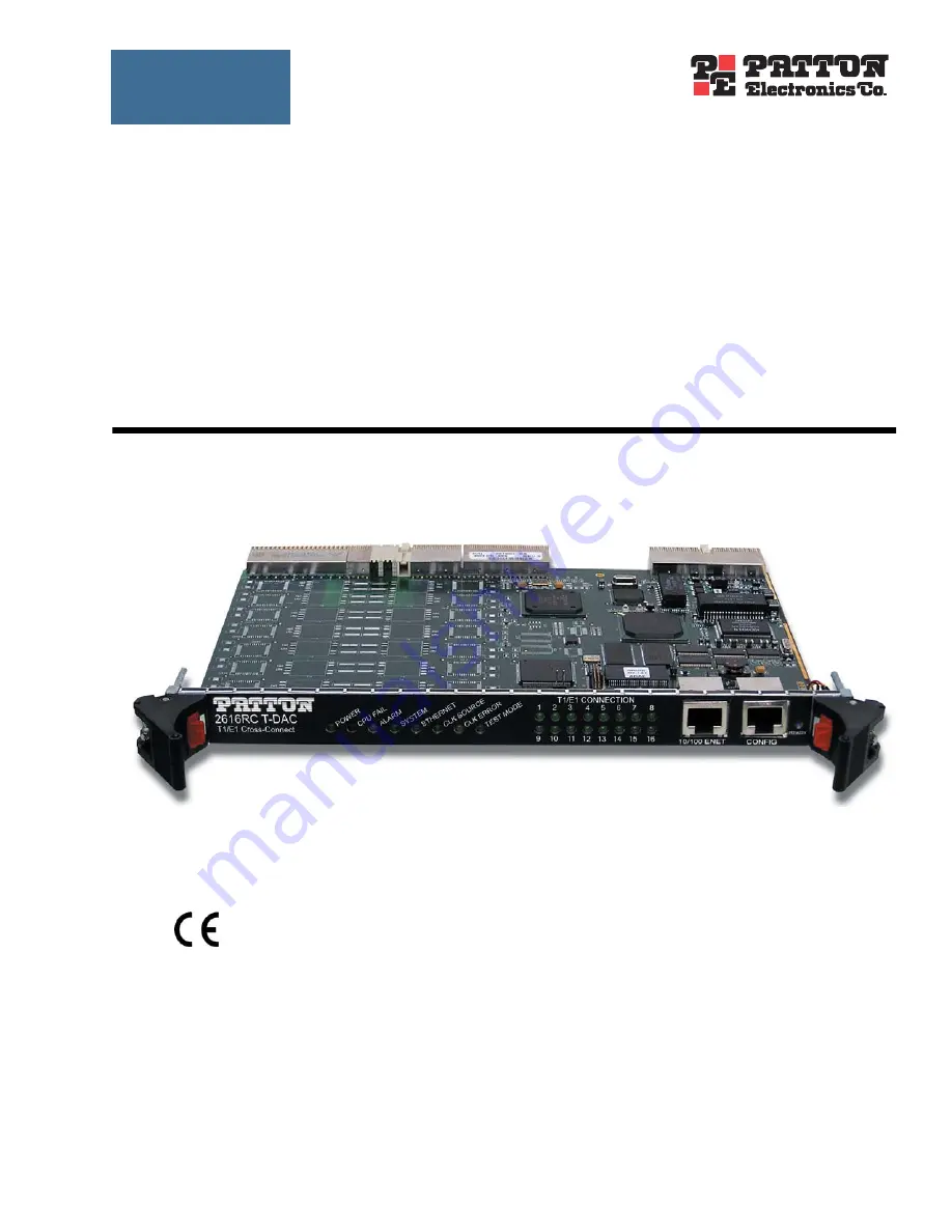
background image


Model 2616RC


T1/E1 TDM-Digital Access 


Concentrator (T-DAC)


Getting Started Guide


Sales Office:


+1 (301) 975-1000


Technical Support:


+1 (301) 975-1007


E-mail:


[email protected]


WWW:


www.patton.com


Document Number: 


11015U1-001 Rev. D


Part Number: 


07MD2616RC-GSG


Revised: 


April 9, 2009


Important


This is a Class A device and is intended for use in a light industrial environment. It is not intended nor approved for use in an industrial 
or residential environment.


See 


Chapter 2


 for installa-

tion procedures &


 Chapter 3


for configuration procedures

Summary of Contents for ForeFront 2616RC

Page 1: ...com WWW www patton com Document Number 11015U1 001 Rev D Part Number 07MD2616RC GSG Revised April 9 2009 Important This is a Class A device and is intended for use in a light industrial environment It is not intended nor approved for use in an industrial or residential environment See Chapter 2 for installa tion procedures Chapter 3 for configuration procedures ...

Page 2: ...ects and will at our option repair or replace the product should it fail within one year from the first date of the shipment This warranty is limited to defects in workmanship or materials and does not cover customer damage abuse or unauthorized modification If the product fails to perform as warranted your sole recourse shall be repair or replacement as described above Under no condition shall Pa...

Page 3: ...ware installation 19 3 Configuring the T DAC for operation 31 4 Operation and shutdown 58 5 Troubleshooting and maintenance 60 6 Contacting Patton for assistance 72 A Compliance information 75 B 68 pin SCSI to open end 6 foot cable part 10 3096TM68 6 78 ...

Page 4: ...del 2616RC T DAC 20 T DAC blades installation 20 Cable installation 22 Connecting the Ethernet ports 22 Connecting the 10 100Base T Ethernet port to an Ethernet switch or hub 22 Connecting the 10 100Base T Ethernet port to an Ethernet capable workstation or PC 23 Connecting the EIA 561 RS 232 configuration port DCE configured 23 Connecting the T1 E1 WAN ports 24 68 pin SCSI to 8 RJ 45 connectors c...

Page 5: ...gnaling for T1 49 Accessing the Line Interface Settings 49 Configuring the T1 line settings 50 Enabling disabling the alarm card 52 Saving your configuration 53 Backing up your configuration parameters 53 Backing up the configuration store in flash memory 55 Completing the installation 56 4 Operation and shutdown 58 Introduction 59 Activating the Model 2616RC 59 De activating the Model 2616RC 59 5...

Page 6: ...it 73 Return for credit policy 74 RMA numbers 74 Shipping instructions 74 A Compliance information 75 Compliance 76 EMC 76 Safety 76 PSTN Regulatory 76 Radio and TV Interference 76 Industry Canada Notice 76 FCC Part 68 ACTA Statement 77 CE Declaration of Conformity 77 Authorized European Representative 77 B 68 pin SCSI to open end 6 foot cable part 10 3096TM68 6 78 Introduction 79 ...

Page 7: ...guration Menu home page 38 25 HOME page window panes 39 26 Operator Actions buttons 39 27 IP Routing Information Page 40 28 IP Routing Information window 41 29 System Clocking Configuration page example 1 42 30 System Clocking Configuration page example 2 43 31 Clock Reference Submit Query button 43 32 Clock Reference Submit Query button 43 33 DS0 Mapping Overview window 44 34 Display Option menu ...

Page 8: ...RT EXPORT page 54 52 Example T DAC flash memory configuration file displayed in a browser 55 53 Saving the access server flash memory configuration data as a text file 56 54 Payload loopback 64 55 Line Loop 65 56 IMPORT EXPORT page 67 57 Example T DAC flash memory configuration file displayed in a browser 68 58 Saving the access server flash memory configuration data as a text file 69 ...

Page 9: ...eneral conventions 12 2 Mouse conventions 12 3 LED definitions 18 4 RJ 45 plug pin out 25 5 WAN cable s 68 non terminated twisted pairs 27 6 Symptoms 61 7 LED definitions 62 8 WAN cable s 68 non terminated twisted pairs 79 ...

Page 10: ... port of the T DAC Audience This guide is intended for the following users Operators Installers Maintenance technicians Structure This guide contains the following chapters and appendices Chapter 1 describes the T DAC Chapter 2 describes installing the T DAC hardware Chapter 3 describes configuring the T DAC for use Chapter 4 details how to power up and deactivate the T DAC Chapter 5 contains trou...

Page 11: ...tly follow the instructions to avoid property damage caused by electric shock The alert symbol and CAUTION heading indicate a potential haz ard Strictly follow the instructions to avoid property damage The Model 2616RC shall be installed in a restricted access location accessi ble only to authorized personnel This unit contains no user serviceable parts Refer servicing to qualified personnel When ...

Page 12: ...ets indicate function and keyboard keys such as SHIFT CTRL C and so on Are you ready All system messages and prompts appear in the Courier font as the system would display them dir Bold Courier font indicates where the operator must type a response or command Table 2 Mouse conventions Convention Meaning Left mouse button This button refers to the primary or leftmost mouse button unless you have ch...

Page 13: ... 2616RC T1 E1 T DAC overview 14 Hardware overview 15 WAN 15 LAN 15 RS 232 control port 16 Power system 16 Central processing unit 16 System timing 16 Temperature 16 Altitude 16 Humidity 16 Physical dimensions 16 Management services 16 LED display 18 ...

Page 14: ...zed web based management system on a front and rear blade for insertion in a Patton ForeFront chassis with a chassis mid plane architecture The front blade contains LED status indicators an RS 232 configuration port and a 10 100 Ethernet management port The rear blade contains the T1 E1 WAN port connections The 16 T1 E1 ports connect to channelized T1 or E1 network connections Each WAN port termin...

Page 15: ...C includes 4 8 12 or 16 ports selectable for T1 or E1 operation The T1 E1 ports may be con nected to ATM FR DDN IP network backbones and are accessible via the 68 pin SCSI connector in the rear of the unit Also included are 4 to 16 built in T1 E1 CSU DSUs T1 1 544 Mbps with D4 or ESF framing AMI or B8ZS line coding FCC part 68 compliant E1 2 048 Mbps multi framing with or without CRC4 framing AMI ...

Page 16: ...ys an Intel i960VH RISC processor operating at 100 MHz 100 Mips The CPU controls the memory front back panel and management interface for WAN time slot mapping local switching loop back and the management system The memory holds 4 MB Flash ROM 8 MB EDO DRAM System timing The T1 E1 T DAC s system timing may be derived from an internal clock from an on board chip external BITS clock or a network clo...

Page 17: ...rsion 1 configuration management MIB II TELNET via Ethernet SYSLOG Client Remote Software Upgrade via FTP Built in HTTP server for complete configuration and control using a standard web browser Frame Relay or PPP in band management via T1 E1 DS0s Figure 3 Model 2616RC front panel LEDs ...

Page 18: ...nal for the Ethernet port No action recommended Off A valid link has not been detected CLK SOURCE Green On solid The 2616RC is set as the Master Clock source Flashing The 2616RC is set as the secondary clock source Off The 2616RC is set as the slave getting its clock from the H 110 Bus CLK ERROR Yellow On solid Master Clock source has been lost and the 2616RC is using the secondary source for its ...

Page 19: ...ng the 10 100Base T Ethernet port to an Ethernet capable workstation or PC 23 Connecting the EIA 561 RS 232 configuration port DCE configured 23 Connecting the T1 E1 WAN ports 24 68 pin SCSI to 8 RJ 45 connectors cable 24 68 pin SCSI to open end cable 26 Installing the WAN cable to a punch down block 28 68 pin SCSI to open end 6 foot cable part 10 3096TM68 6 Obsolete 29 68 pin SCSI to 64 pin femal...

Page 20: ...laim purposes Save all packing materials in case you need to return an item to the factory for servicing The T DAC comes with the following items The Model 2616RC Digital Cross Connect T DAC One RJ45 to RJ45 cable for use with the console and Ethernet ports A DB9 RJ45 EIA 561 adapter for connecting a PC s serial port to the T DAC console port Model 2616RC T DAC Getting Started Guide CD ROM contain...

Page 21: ...ignment ESD pin and card handle 3 Gently press the blade into the chassis until the alignment ESD pin see figure 4 engages the chassis When the blade is fully seated the red buttons in the handles click up automatically thus locking the han dle and activating the switch closed position The click of the button gives a visual and audible confirma tion that the board is fully seated 4 Insert the fron...

Page 22: ... full duplex operation This sec tion describes connecting the T DAC to the Ethernet LAN via an Ethernet hub switch or workstation Figure 5 Model 2616RC network and configuration ports Connecting the 10 100Base T Ethernet port to an Ethernet switch or hub The 10 100Base T Ethernet port see figure 5 is designed to connect to an Ethernet switch or hub The Ethernet RJ 45 pin and signal definitions for...

Page 23: ...r to figure 7 to assemble a cross connect cable that will connect between the NIC Ether net port in the workstation and the T DAC 10 100Base T Ethernet port Figure 7 Cross over RJ 45 to RJ 45 Ethernet cable diagram Connecting the EIA 561 RS 232 configuration port DCE configured Install the supplied RJ 45 to RJ 45 cable with the DB9 RJ45 adapter between the T DAC RS 232 port see figure 5 on page 22...

Page 24: ...I to 8 RJ 45 connectors cable for installation details 68 pin SCSI to 16 RJ 45 connectors cable 6 foot 1 8 m part 10 3096TM68 16RJ45 6 see section 68 pin SCSI to 8 RJ 45 connectors cable for installation details 68 pin SCSI to open end 12 foot 3 6 m part 10 3096TM68 12 see section 68 pin SCSI to open end cable for installation details 68 pin SCSI to 8 RJ 45 connectors cable The SCSI to RJ 45 cable...

Page 25: ... figure 10 of the 6 foot WAN cable see figure 9 on page 24 to the connector on the rear panel of the Model 2616RC 2 Connect the WAN cable RJ 45 connectors see figure 11 to the corresponding ports on a patch panel or local T1 E1 device Figure 11 RJ 45 plug Table 4 RJ 45 plug pin out Description Pin Transmit pair TX 1 Transmit pair TX 2 Receive pair RX 4 Receive pair RX 5 ...

Page 26: ...SI to open end cable see figure 12 connects the 2616RC T1 E1 lines to a punch down block via 24 gauge solid wire 0 5mm The other end will be unterminated open end twisted pairs Refer to table 5 for punch down block wiring information Figure 12 SCSI to open end WAN cable Figure 13 68 pin SCSI connector 68 pin SCSI connector ...

Page 27: ... 54 Brown Violet Violet Brown Port 3 TX 5 5 39 White Violet Violet White Port 11 TX 21 21 55 Brown Blue Blue Brown Port 3 RX 6 6 40 White Blue Blue White Port 11 RX 22 22 56 Brown Yellow Yellow Brown Port 4 TX 7 7 41 White Yellow Yellow White Port 12 TX 23 23 57 Brown Green Green Brown Port 4 RX 8 8 42 White Green Green White Port 12 RX 24 24 58 Brown Gray Gray Brown Port 5 TX 9 9 43 White Gray Gr...

Page 28: ... between SCSI cable entry point on the punch down block frame and the farthest port to be wired on the punch down block see figure 14 Figure 14 Punch down block wiring 2 Strip SCSI cable insulation and shielding based on the measurement made in step 1 33 67 NOT USED 34 68 NOT USED Table 5 WAN cable s 68 non terminated twisted pairs Continued Port Directio n Pairs 68 Pin Positions Wire Color Code P...

Page 29: ...le part 10 3096TM68 6 Obsolete 1 This 6 foot WAN cable see figure 15 connects the 2616RC T1 E1 lines to a punch down block via 28 gauge wire 0 3mm Check your punch down block wire gauge requirements as most punch down blocks will not hold 28 gauge wire securely in place Figure 15 SCSI to open end 6 foot WAN cable obsolete 2 See appendix B 68 pin SCSI to open end 6 foot cable part 10 3096TM68 6 on ...

Page 30: ...ough the 47 pin PICMG 2 11 power con nectors on the 2616RC blades Upon insertion into the Patton ForeFront chassis the Model 2616RC immedi ately powers up and begins its boot cycle During the boot cycle the following should occur 1 The POWER LED illuminates indicating normal power is being applied to the 2616RC 2 The green SYSTEM LED begins flashing indicating the 2616RC is operating normally Hard...

Page 31: ...es 38 Home page overview 38 Configuring the default gateway 40 Configuring the system clocking parameters 41 Configuring the DS0 mapping 44 Configuring line settings and signaling for E1 46 Accessing the Line Interface Settings 46 Configuring the E1 line interface settings 47 Configuring line settings and signaling for T1 49 Accessing the Line Interface Settings 49 Configuring the T1 line settings...

Page 32: ...cking parameters see page 41 Defining the IP default gateway see page 52 Enabling the alarm card see page 40 Saving your configuration on page 53 describes how to save your configuration settings Backing up your configuration parameters on page 53 describes how save your configuration parame ters to a file Completing the installation on page 56 describes how to verify that your 2616RC T DAC is ful...

Page 33: ...netmask from the default settings Note Do not connect power or the Ethernet connection to the Model 2616RC at this time Connecting the DB9 RJ45 adapter with the included cable Do the following 1 Find the DB9 RJ45 adapter for your PC and RJ 45 to RJ45 cable shipped with your 2616RC T DAC 2 Connect the DB9 RJ45 adapter to your PC s RS 232 serial port 3 Connect the RJ45 RJ45 cable between the adapter...

Page 34: ... double clicking on the file name Figure 17 Connection Description window 2 Type a connection name e g 2616RC Config select an icon then click OK figure 18 Figure 18 Connect To window 3 On the Connect To window figure 18 set Connect using to one of the options named Direct to ComX where the X refers to the number identifying the RS 232 serial port on the PC In the following proce dure Com1 will be...

Page 35: ... for operation 6 Configure your COM port settings as shown in figure 19 then click OK Figure 19 COM1 Properties window 7 Click on the File menu then select Properties 8 Configure the settings for Function arrow and ctrl keys act as to Terminal keys as shown in figure 20 then click OK Figure 20 Terminal keys configuration ...

Page 36: ...T DAC s power cables to the power outlets 10 Boot up information will display on your HyperTerminal connection window eventually followed by a login request window see figure 21 Figure 21 Login window 11 For the user name type superuser 12 For the password type superuser the top level management window then appears see figure 22 Figure 22 VT 100 top level management window ...

Page 37: ...P address 18 Press the left arrow cursor key until the top level management window displays see figure 22 on page 36 19 Type a for HOME then press Enter 20 Under the Current Status page type 1 store Config 1 to save the changes you have just made to the configuration This completes the initial configuration of the Model 2616RC The next steps in configuration will be done using your Web browser con...

Page 38: ... not have an IP address in your TDAC refer to Initial configuration through the RS 232 control port on page 33 4 A login prompt will appear In the username field type superuser then press Tab to move the cursor to the Password field In the password field type superuser then press Enter 5 The 2616RC Configuration Menu home page will appear see figure 24 Figure 24 2616RC Configuration Menu home page...

Page 39: ...he configuration is saved into FLASH memory the configuration will not be lost even if the power is cycled on the 2616RC Initially changes made to the 2616RC configuration are stored in volatile DRAM enabling the user to set the box up with a working configuration before committing it to storage in FLASH When you select Record Current Configuration the 2616RC stores your changes to FLASH memory No...

Page 40: ...ticular installation You will have to re enter the Model 2616RC s Ethernet IP address and net mask using the rear panel control port before using the HTTP HTML Management pages Configuring the default gateway The default gateway IP address if defined is used solely for managing the 2616RC remotely via the Ethernet port The 2616RC does not transmit or receive user data nor any other traffic via the...

Page 41: ...he master will drive the main reference clock for the chassis Should the master fail the secondary will drive the main reference Slaves will not drive any clock reference Most often the 2616RC will be configured as slave 3 with another blade such as the Patton Model 6511 configured as the master 1 You can choose any one of the WAN ports an internal oscillator or system clock provided by the ForeFr...

Page 42: ...fallback reference clock 9 Click the Submit Query button Example 2 Another card such as the Patton Model 6511 is the clocking master and your 2616RC is a secondary or slave This example assumes you will use the system clock as the main reference and WAN port 1 as the fallback ref erence To define the clocking source do the following Note If there are two or more ForeFront TDM cards 6511RC 3096RC 2...

Page 43: ...ary 2 or slave 3 Note If slave is selected you will not be able to configure the main or fall back reference If you selected slave 3 go to step 6 Otherwise con tinue on to step 4 4 If you selected secondary 2 in step 3 for Main Reference select system 500 5 For Fallback Reference select wan 1 1 6 Click the Submit Query button shown in figure 31 Figure 31 Clock Reference Submit Query button 7 Selec...

Page 44: ...rt on another card or a DSL port on a Patton Model 3096RC within the chassis In this scenario DS0s are first mapped from the originating 2616RC card T1 E1 port to a H 110 port chassis TDM system bus The destination card similarly must have a DS0 map from the H 110 bus to the appropriate T1 E1 port Mapping DS0s from a T1 E1 port to an STM 1 card in the same chassis In this scenario the 2616RC first...

Page 45: ...ots on the A and B sides of the connection The slots are defined by entering a text string that represents the slots For the T1 E1 ports the slots that are available are 1 32 For a WAN port configured as a T1 the available slots are numbered from 1 24 For a WAN port configured as an E1 the available slots are 1 32 The H 110 TDM system bus is comprised of 32 ports each port contains 128 unidirectio...

Page 46: ...A select t1 e1 1 2 Under Dev Num A select port10 10 3 Under Dev Slots A enter 1 32 4 Under Dev Type B select fromH110 5 Under Dev Num B select port1 1 6 Under Dev Slots B enter 1 32 7 Under Dev Type B select toH110 8 Under Dev Num B select port1 1 9 Under Dev Slots B enter 32 62 10 Click the Submit Query button Configuring line settings and signaling for E1 Accessing the Line Interface Settings 1 ...

Page 47: ...en the T1 E1 LINK ACTIVITY PORTS 1 4 page see figure 36 Figure 36 T1 E1 Link Activity Ports 1 4 page 3 Click the Configuration hyperlink then click the Modify Configuration hyperlink to open the WAN Circuit CONFIGURATION LINK window see figure 37 and view the Line Interface Settings Figure 37 WAN Circuit Configuration page Line Interface Settings Configuring the E1 line interface settings 1 From t...

Page 48: ...DB3 3 selected 3 From the Line Build Out pull down menu figure 40 select e1pulse 1 Figure 40 Line Build Out pull down menu with e1pulse 1 selected 4 Click the Submit Query button to apply your line interface settings At this point the T1 E1 front panel LEDs will become active The T1 E1 indicator LEDs should now display a steady green light indicating the T DAC has synchronized with the E1 line If ...

Page 49: ...ar Configuring line settings and signaling for T1 Accessing the Line Interface Settings 1 On the 2616RC Configuration Menu click the T1 E1 Link hyperlink to open the T1 E1 LINK ACTIV ITY OVERVIEW page figure 42 Figure 42 T1 E1 Link Activity Overview page 2 View Link 1 corresponds to the first WAN circuit on the T DAC To the right of View Links 1 4 click the View Links hyperlink to open the T1 E1 L...

Page 50: ...ion hyperlink to open the WAN Circuit CONFIGURATION LINK window figure 44 and view the Line Interface Settings Figure 44 WAN Circuit Configuration page Line Interface Settings Configuring the T1 line settings 1 From the Line Type pull down menu figure 45 select either dsx1ESF 2 indicates Extended SuperFrame DS1 dsx1D4 indicates AT T D4 format DS1 Figure 45 Line Type pull down menu with dsx1ESF 2 s...

Page 51: ...pull down menu with t1pulse0dB 1 selected 4 Click on Submit Query to apply your settings At this point the T1 E1 front panel LEDs will become active The T1 E1 indicator LED should now display a steady green light indicating the T DAC has synchronized with the E1 line If the E1 line is not connected to the 2616RC T1 E1 link pages will display the hyperlink ALARMS PRESENT figure 48 for that T1 E1 li...

Page 52: ...the chassis 1 Click on Alarm Card under the configuration menu to display the Alarm Card Information window 2 From the Alarm Card Polling Mode menu select an option from the drop down menu to enable disable the alarm card doNotMonitor 0 Disables the alarm card monitorAlarmCard 1 Enables the alarm card 3 Click Submit to save the change Note If the chassis contains more than one 2616RC 3096RC 3196RC...

Page 53: ...r rent Configuration button before you power down or reset the T DAC Backing up your configuration parameters The 2616RC T DAC provides Import Export functions These functions enable you to back up export and restore import your T DAC s configuration parameters against possible failure Should your T DAC ever need replacing a previously saved copy of your exported configuration file can quickly be ...

Page 54: ...DAC Getting Started Guide 3 Configuring the T DAC for operation To import or export a configuration do the following 1 On the Configuration Menu pane click the Import Export hyperlink to display the IMPORT EXPORT page see figure 51 Figure 51 IMPORT EXPORT page ...

Page 55: ... 1 To make a back up copy of the configuration file currently stored in your T DAC s flash memory On the Import Export page figure 52 click the Export Flash hyperlink The T DAC will get the con figuration file currently stored in your T DAC s flash memory and display it in your browser figure 52 Figure 52 Example T DAC flash memory configuration file displayed in a browser ...

Page 56: ... a text file Completing the installation This section verifies that the Model 2616RC is fully operational 1 Temporarily disconnect the male ends of both power cords from the power outlet Wait 30 seconds then plug the power cords in again 2 Verify the green POWER LED is lit If the POWER LED is flashing green refer to Chapter 5 Trouble shooting and maintenance 3 Verify that the WAN LED illuminates i...

Page 57: ...ndicate the status of the T DAC 10 100 Ethernet port a green LED indicates link status and activity and a yellow LED that indicates line speed Verify that the green LED is either flashing green meaning that packets are being received at the Ethernet port or solid green meaning that the link is valid but no packets are being received Congratulations Your T DAC is now installed If you require furthe...

Page 58: ...58 Chapter 4 Operation and shutdown Chapter contents Introduction 59 Activating the Model 2616RC 59 De activating the Model 2616RC 59 ...

Page 59: ...alled and configured no further operator action is required under normal conditions De activating the Model 2616RC Perform the following procedure to deactivate the Model 2616RC Note Be sure to wear an anti static strap to prevent electrostatic damage to the blade 1 Unlock the handles on the front of the 2616RC by pressing the red button on each handle The button immediately activates the switch t...

Page 60: ... DSX1 payload loop dsx1PayloadLoop 64 DSX1 line loop dsxLineLoop 65 Periodic maintenance 66 Calibration 66 Maintenance 66 Exporting the current Model 2616RC configuration 66 Removing the defective Model 2616RC 69 Installing the replacement Model 2616RC 70 Importing a saved configuration 70 Completing the installation 71 ...

Page 61: ...ower supply module If no failed power supply is found or if the POWER LED continues flashing contact Patton Technical Support to determine if the T DAC should be replaced CPU FAIL LED red is lit CPU is unable to load the software from FLASH to RAM for operation As soon as possible remove the Model 2616RC from the Patton ForeFront chassis wait 30 seconds then re insert the Model 2616RC into the Pat...

Page 62: ...he Model 2616RC will function normally with one power sup ply Inspect the power supplies in the Patton ForeFront chassis to identify and replace the failed power supply module If the POWER LED continues flashing when all chassis power supplies are functional contact Patton Technical Support to determine if the T DAC should be replaced Off No input power is being applied Verify that at least one ch...

Page 63: ...to determine if the T DAC should be replaced CLK SOURCE Front panel Green On solid The 2616RC is set as the Master Clock source No action rec ommended Flashing The 2616RC is set as the secondary clock source No action recommended Off The 2616RC is set as the slave getting its clock from the H 110 Bus No action recommended CLK ERROR Front panel Yellow On solid Master Clock source has been lost and ...

Page 64: ...the Modify Configuration link of the T1 E1 port to be placed under test 2 Locate the Loopback Configuration drop down menu 3 Select Payload Loop and click on the Submit Query button on the right To deactivate payload loop set the Loopback Configuration drop down menu to NoLoop READY Front panel Blue On Card ready for removal from Patton ForeFront chassis Off Card not ready for removal from Patton ...

Page 65: ...Line Loop To activate line loop do the following 1 Click on the Modify Configuration link of the T1 E1 port to be placed under test 2 Locate the Loopback Configuration drop down menu 3 Select LineLoop and click on the Submit Query button on the right To deactivate payload loop set the Loopback Configuration drop down menu to NoLoop and click on the Sub mit Query button on the right Note Refer to t...

Page 66: ... configuration parameters against possible failure Should your T DAC ever need replacing a previously saved copy of your exported configuration file can quickly be loaded imported into a replacement T DAC Note Import Export functions require superuser access privileges Note The parameters that will be exported are the power up settings as they are stored in flash memory and may not be the current ...

Page 67: ...Maintenance 67 Model 2616RC T DAC Getting Started Guide 5 Troubleshooting and maintenance Figure 56 IMPORT EXPORT page ...

Page 68: ...file currently stored in your T DAC s flash memory On the Import Export page figure 56 on page 67 click the Export Flash hyperlink The T DAC will get the configuration file currently stored in your T DAC s flash memory and display it in your browser figure 57 Figure 57 Example T DAC flash memory configuration file displayed in a browser ...

Page 69: ...e file Type a file name Click Save Figure 58 Saving the access server flash memory configuration data as a text file Removing the defective Model 2616RC 1 Remove the replacement Model 2616RC from its shipping container and place it near the chassis in which the malfunctioning Model 2616RC is located Note The Model 2616RC T DAC blades are hot swappable so it is not necessary to deactivate the rack ...

Page 70: ...ng cables to the Model 2616RC The T1 E1 WAN cable 68 pin SCSI connector The RS 232 CONFIG cable The 10 100 ETHERNET cable 5 Verify that the green POWER LED is lit Importing a saved configuration Before importing a saved configuration you must define the Model 2616RC s IP address and netmask These parameters are defined via the Model 2616RC RS 232 CONFIG port on the Model 2616RC 1 Refer to Chapter ...

Page 71: ... synchronizing with the T1 E1 signal 3 Verify that after 5 seconds the WAN LED begins flashing indicating that the Model 2616RC is satisfied with the quality of the T1 E1 signal 4 Verify that after 10 seconds the WAN LED extinguishes indicating that the Model 2616RC is satisfied with the network signal and that the link is ready for use 5 Verify that the green Ethernet LED is either flashing indic...

Page 72: ...er contents Introduction 73 Contact information 73 Warranty Service and Returned Merchandise Authorizations RMAs 73 Warranty coverage 73 Out of warranty service 73 Returns for credit 73 Return for credit policy 74 RMA numbers 74 Shipping instructions 74 ...

Page 73: ... are carefully tested before ship ment All of our products are backed by a comprehensive warranty program Note If you purchased your equipment from a Patton Electronics reseller ask your reseller how you should proceed with warranty service It is often more convenient for you to work with your local reseller to obtain a replacement Patton services our products no matter how you acquired them Warra...

Page 74: ...ting a request on the RMA Request page in the Support section at www patton com By calling 1 301 975 1000 and speaking to a Technical Support Engineer By sending an e mail to returns patton com All returned units must have the RMA number clearly visible on the outside of the shipping container Please use the original packing material that the device came in or pack the unit securely to avoid damag...

Page 75: ...ormation Chapter contents Compliance 76 EMC 76 Safety 76 PSTN Regulatory 76 Radio and TV Interference 76 Industry Canada Notice 76 FCC Part 68 ACTA Statement 77 CE Declaration of Conformity 77 Authorized European Representative 77 ...

Page 76: ...nt into a different AC outlet such that the computing equip ment and receiver are on different branches Industry Canada Notice This equipment meets the applicable Industry Canada Terminal Equipment Technical Specifications This is confirmed by the registration number The abbreviation IC before the registration number signifies that regis tration was performed based on a Declaration of Conformity i...

Page 77: ...customer as soon as possible Also you will be advised of your right to file a complaint with the FCC if you believe it is necessary The telephone company may make changes in its facilities equipment operations or procedures that could affect the operation of the equipment If this happens the telephone company will provide advance notice in order for you to make necessary modifications to maintain ...

Page 78: ...78 Appendix B 68 pin SCSI to open end 6 foot cable part 10 3096TM68 6 Chapter contents Introduction 79 ...

Page 79: ...let Violet White Port 11 TX 21 21 55 Brown Blue Blue Brown Port 3 RX 6 6 40 White Blue Blue White Port 11 RX 22 22 56 Brown Yellow Yellow Brown Port 4 TX 7 7 41 White Yellow Yellow White Port 12 TX 23 23 57 Brown Green Green Brown Port 4 RX 8 8 42 White Green Green White Port 12 RX 24 24 58 Brown Gray Gray Brown Port 5 TX 9 9 43 White Gray Gray White Port 13 TX 25 25 59 Pink Orange Orange Pink Por...

Page 80: ...Introduction 80 Model 2616RC T DAC Getting Started Guide B 68 pin SCSI to open end 6 foot cable part 10 ...

Reviews: