Notice to Customer
Thank for your purchasing our PATLITE products.
The WDB-D80S-PRO and WDT-6LR-Z2-PRO are WD
PRO Series products. For the WDR-LE-Z2, refer to
☞
"WDT-5LR-Z2/WDT-6LR-Z2 Instruction Manual."
●Request the installation and wiring be performed
by a professional contractor if construction work is
involved.
●Prior to installation, read this manual thoroughly
before using this product to ensure correct use.
●Re-read this manual before conducting maintenance,
inspections, repairs, and so on. If you have any
questions about this product, please contact our
service and repair desk.
●When using the system operation software WDS-
WIN01, use version 1.03 or later.
To the Contractor
●Prior to installation, read this manual thoroughly to
ensure it is installed correctly.
●Return this manual to the customer.
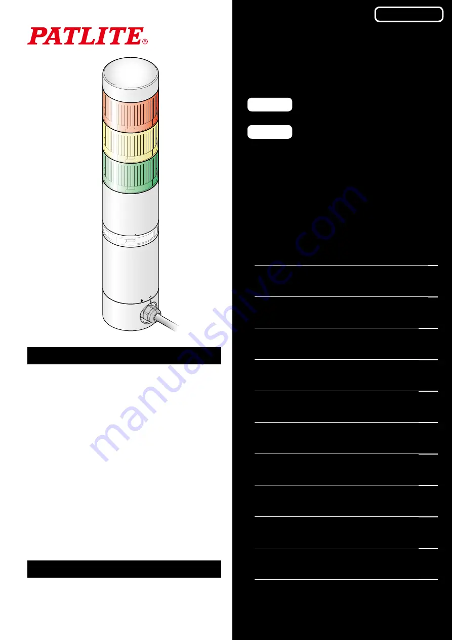
Wireless Data Communication System
WD PRO Series
TYPE
WDB-D80S-PRO
TYPE
WDT-6LR-Z2-PRO
Instruction Manual
[Web Version]
Page
11. Replacement and Optional Parts
GA0000937_02