Instruction Manual
012-07227G
*012-07227*
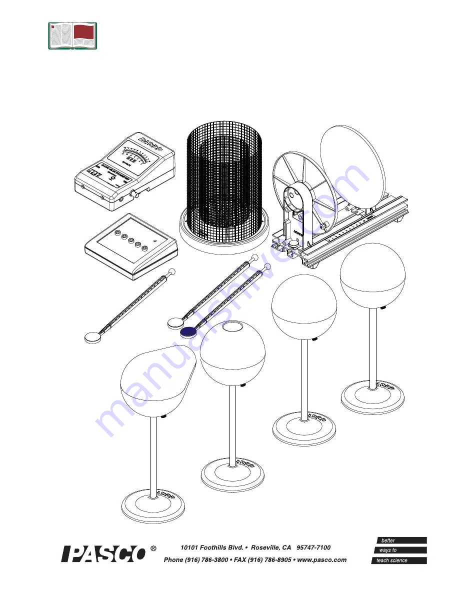
Basic Electrostatics System
ES-9080
B
Page 1: ...Instruction Manual 012 07227G 012 07227 Basic Electrostatics System ES 9080B...
Page 2: ...Pail 9 Conductive Spheres 10 Conductive Shapes 10 Electrometer Operation and Setup Requirements 11 Suggested Demonstrations 13 34 Demonstration 1 Faraday Ice Pail and Charge Production 13 16 Demonstra...
Page 3: ...1 Basic Electrometer cables not shown ES 9078A 2 Electrostatics Voltage Source cable and AC adapter not shown ES 9077 3 Basic Variable Capacitor cable not shown ES 9079 4 Faraday Ice Pail and Shield...
Page 4: ...lectrometer ES 9078 in a computer screen that all can easily see You can use an analog display for example to show the deflections of the needle or a digits display to show the voltage If a computer i...
Page 5: ...tance of the electrometer must be considered when calculating the magnitude of a charge from the voltage reading of the electrometer See Demonstration 3 for the procedure necessary to determine the el...
Page 6: ...y for experiments in electrostatics It has outputs at 30 volts DC for capacitor plate experiments and 1 kV 2 kV and 3 kV outputs for the Faraday ice pail and conductive sphere experiments All of the v...
Page 7: ...cally Keep the plate supports clean to prevent charge leakage from the plates Charge Producers and Proof Plane ES 9057B The Charge Producers and the Proof Plane are electrostatic components for use wi...
Page 8: ...carbonate about 1014 The proof plane can be used to sample the charge density on charged conductive surfaces A Faraday Ice Pail and Electrometer can then be used to measure the charge density on the p...
Page 9: ...The outer cylinder is called the shield It provides complete visibility to the inside of the pail and when grounded helps eliminate stray charges and AC fields The inner cylinder is the actual pail T...
Page 10: ...mize charge leakage from the sphere Conductive Shapes ES 9061 The conductive shapes are special objects upon which to store electrical charges Both shapes are made of nickel plated ABS plastic The Con...
Page 11: ...charge the setup procedure should be followed each time you turn on the electrometer Warning To avoid electrical shock and or injury observe the following safety precautions 1 Never use the electrome...
Page 12: ...2 Shorting the test leads together is insufficient There may still be stray charges within the electrometer circuitry 3 For good results it is essential that the electrometer be connected to an earth...
Page 13: ...s can tell us the type of charge in the ice pail Equipment Setup Introduction The purpose of this demonstration is to investigate the relation between the charge induced on the ice pail by a charged o...
Page 14: ...hould read zero when grounded indicating there is no charge in the ice pail Press the ZERO button to completely remove all charge from the electrometer and the ice pail 2 Always start with the voltage...
Page 15: ...disk ground the ice pail to remove all charge Press the ZERO button to remove residual charges from the electrometer Insert the charge producer again into the ice pail Does any charge remain on it Pro...
Page 16: ...Extra Things to Try 1 Try repeating Procedure 1A with the opposite charged wand 2 Try rubbing the white charge producer with a proof plane then measure the magnitude and polarity of the charges produc...
Page 17: ...ude or even in sign This occurs for non uniform charge distribution Alternately you may observe that everywhere on the surface the charge has the same magnitude and sign This occurs for uniform charge...
Page 18: ...rostatic Voltage Source ES 9077 The voltage source should be grounded to the same earth ground as the shield and the electrometer An earth ground for the system is the AC adapter power supply for the...
Page 19: ...arge inside the sphere Analysis 1 How do the charges compare between the outside of the hollow sphere and the inside of the hollow sphere Extra Things to Try 1 To show that the charge on a conductor a...
Page 20: ...Basic Electrostatics System ES 9080B 20...
Page 21: ...an infinite impedance voltmeter in parallel with a capacitor as shown in Figure 3 1 The capacitor CE represents the internal capacitance of the electrometer plus the capacitance of the leads Whenever...
Page 22: ...e the capacitor with a known voltage V not higher than 100 V the limit of the electrometer 3 Remove the charged capacitor from the power supply used to charge it being careful not to ground it in any...
Page 23: ...transfer charge from the charged sphere to the capacitor plates The charge is transferred merely by touching the proof plane to the sphere and then to one capacitor plate If you always touch the spher...
Page 24: ...use it to examine the charge density of the capacitor using the ice pail to measure the charge Investigate the charge density at various points on the plates both on the inner and the outer surfaces...
Page 25: ...n the voltage source 2 Keep the plate separation constant and change the potential across the plates by changing the setting of the voltage source You have to move the connecting cable from the 3000 V...
Page 26: ...reading of about 1 5 scale 3 Increase the plate separation and note the electrometer s readings at various separations How does the potential vary with capacitance NOTE An alternative method is to ch...
Page 27: ...choose one to keep fixed and the other to be the movable one 1 Connect the electrometer across the plates of the capacitor and set the separation between the plates to about 3 mm 2 Raise the side of t...
Page 28: ...the dielectric Let qE be the charge on CE the internal capacitance of the electrometer Let Vi be the initial reading of the electrometer The total charge in this initial system is given by qp qE Cp C...
Page 29: ...n is to examine the effect of placing capacitors in series and in parallel You will need two capacitors of known value between 200 400 F to ignore the internal capacitance of the electrometer a DC vol...
Page 30: ...alues of capacitance determine the amount of charge in each of them Q1 and Q2 7 Questions Can you find a relation between V1 V2 and the voltage of the source How does Q1 and Q2 relate to the original...
Page 31: ...nge so that the internal capacitance of the electrometer needs not be considered You can adjust the resistance value for a convenient RC constant There are two variations of the same activity presente...
Page 32: ...he experiment with different values of R and notice the differences in charging time Analysis When a capacitor is charged through a resistor from a DC power supply the charge on the capacitor and the...
Page 33: ...charge equals the period of the wave Note The procedure listed here specifies values for R C and the frequency of the signal that work well together If you decide to use any other R or C value you hav...
Page 34: ...0 45 Hz Set the signal generator to AUTO In this way the signal will turn on and off as you press Start or Stop to collect data 4 Start recording data Observe the behavior of the voltage across the c...
Page 35: ...roduct which is deemed to be defective in material or workmanship The warranty does not cover damage to the product caused by abuse or improper use Determination of whether a product failure is the re...
Page 36: ...laws and regulations to ensure that it will be recycled in a manner that protects human health and the environment To find out where you can drop off your waste equipment for recycling please contact...