Blast Box Portable Bluetooth Speaker Kit
Thank you for purchasing the Blast Box Portable Bluetooth speaker kit. This speaker kit was
precision cut using CNC machinery for the best possible fit and finish. With a little time and
patience, your finished product will provide years of enjoyment. Please follow the following
instructions for the best possible results.
Follow this link to see the Blast Box assembly video:
https://youtu.be/XgAn3-kQjNQ
Follow this link to hear a Blast Box sound test:
https://youtu.be/Ofy5A0m4xvQ
Suggested tools and consumables:
Drill
Rag or paper towels
Screwdriver
Solder
Wood clamps (you can never have too many of these)
Soldering iron
Sanding block and/or electric finishing sander
Hot glue gun
Wood glue
Polyurethane glue (Gorilla Glue)
Wire stripper/crimper
Wrench/pliers
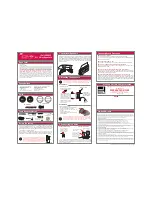
Package contents:
First, empty the contents of the package and review parts to ensure everything has been included and
is in good condition. If any parts are missing or damaged please contact our customer service
department at 1-800-338-0531.
Note: Crossover components may be substituted with parts of equal or higher quality depending on
stock.
Main Components:
a)
TPS3116D2 Class D 2.1 Bluetooth 4.0 Amplifier Board with Filter and Volume Control
b)
Dayton Audio DCS165-4 6-1/2" Classic Subwoofer 4 Ohm
c)
Dayton Audio DS215-PR 8" Designer Series Passive Radiator
Summary of Contents for Blast Box
Page 19: ...Blast Box Crossover Schematic...