ANDERSON INSTRUMENT CO. • 156 AURIESVILLE RD. • FULTONVILLE, NY 12072 USA • 1-800-833-0081 • FAX 518-922-8997
ANDERSON EUROPE CALL 2-353-1520 • FAX 2-353-1533
G A U G E S
T H E R M O M E T E R S
T R A N S M I T T E R S
R E C O R D E R S
C O N T R O L L E R S
L I Q U I D L E V E L S Y S T E M S
R T D S
Installation, Wiring, Operation Manual
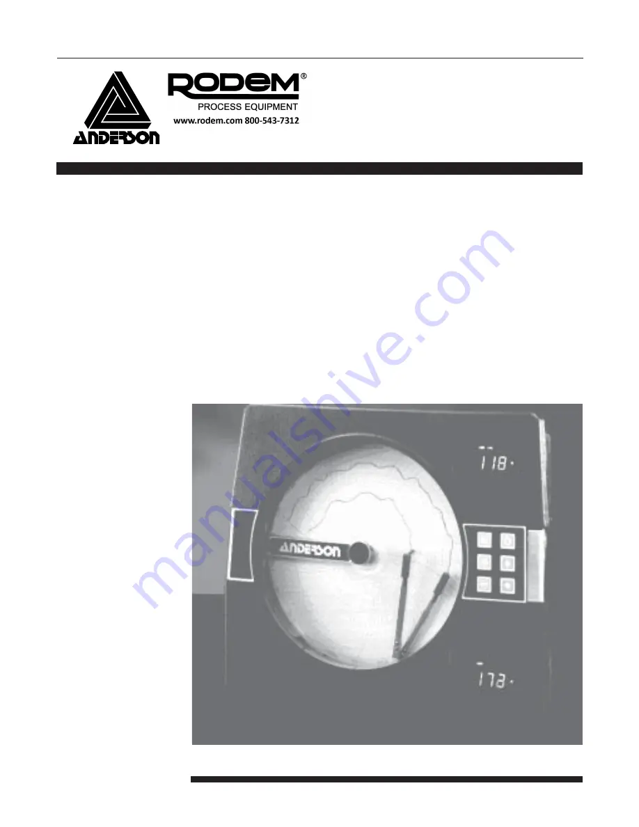
ONE AND TWO PEN CIRCULAR CHART RECORDER
Form AIC 3382
Edition 2 © December 1996
ACR 710
Summary of Contents for ANDERSON AIC 3382
Page 26: ...26 ...
Page 27: ...27 ...
Page 50: ...50 Appendix A Board Layout Jumper Positioning FIGURE A 1 PROCESSOR BOARD ...