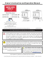
background image

 RAFAEL 55

WARNING:

PROFESSIONAL INSTALLATION 

IS HIGHLY RECOMMENDED


Improper installation, adjustment, alteration, or

maintenance can cause injury, property damage,

or loss of life. For assistance or additional

information, consult an authorized dealer.


Manufactured by 

Paromax Inc.

900 Michèle-Bohec Suite 101

Blainville Qc 

Canada J7C 5E2

IMPORTANT INFORMATION:


Model:


Serial Number:


Purchase date:


Purchased 

from: 


Please note your serial number when

calling for technical support (see page 4)


IMPORTANT : Read the manual before using the Rafael

USER MANUAL & MAINTENANCE

Paromax

inc

.

Ver. RAE 11.9A  September 2011

Report No. 120-S-01B-2
Tested to:   ASTM E1509-04,


    ULC S627-00, 


    ULC/ORD C1482-M1990 

Summary of Contents for RAFAEL 55

Page 1: ...d dealer Manufactured by Paromax Inc 900 Mich le Bohec Suite 101 Blainville Qc Canada J7C 5E2 IMPORTANT INFORMATION Model Serial Number Purchase date Purchased from Please note your serial number when...

Page 2: ...ur area Local regulations and requirements can supersede those specified in this manual if more stringent The authority having jurisdiction such as municipal building department fire department fire p...

Page 3: ...L with corn or wheat Preparing the unit for corn or wheat Clinker prevention Controlling the fuel bed embers level How to measure the fuel bed height Pressure gauge setting Fuel consumption correction...

Page 4: ...TE 3 7 6 CM 6 15 CM 8 20 CM 3 7 6 CM Stove ADJACENT WALL 30 76 2 CM MAX 4 10 CM 3 7 6 CM SEE NOTE S t o v e 6 15 CM 6 15 2 CM 6 15 2 CM 6 15 2 CM FRONT Stove NON COMBUSTIBLE FLOOR PROTECTION Report No...

Page 5: ...s AC Europe with ground connection 15 It is strongly recommended to install a smoke detector and an ABC type fire extinguisher near the unit Using a power surge protector bar helps protect the electri...

Page 6: ...talled If using an outside air supply the unit must be bolted to the floor See mobile home installation for more information Refer to Outside inlet Installation on page 8 The flooring under the stove...

Page 7: ...ails Do not use a non approved pipe for your vent system i e Dryer vent B vent for gas vent PVC plastic pipe or single wall chimney system Please note that the length of a horizontal venting system sh...

Page 8: ...y polarity inver sion that may damage the control panel see picture 35 on page 34 8 Installation A chimney installation with natural draft may create a malfunction due to high pres sure If necessary o...

Page 9: ...the side of the base letter A and use metal spacer to adjust the lowest side And then level the front by placing the level on the front of the base B When burning agriculture fuel Paromax suggests inc...

Page 10: ...anada Note Local codes or regulations may require different clearances Minimum Description A 24 61 cm Above lawns top of plants wood or any other combustible materials A 12 30 5 cm Above non combustib...

Page 11: ...UFACTURER Refer to the norm CAN CSA B365 01 before installing the vent Equivalent Vent length EVL Venting your unit is crucial for optimum operation There are five different installation examples reco...

Page 12: ...EVL Elevation above 3000 ft with an EVL of 7 must adapt to 4 inch vent pipe If your installation is below 3000 ft Rule of installation is to have the sum of the EVL 15 or less For a sum of more than...

Page 13: ...nual feed will function between 3 to 4 minutes Make sure all doors are closed when the manual feed procedure is flashing Tabs 1 Is used to select the language Note Press the OK icon to accept your sel...

Page 14: ...pressure gauge chapter and chart on page 20 To access ash removal settings Press on the trash icon bottom left to adjust the quantity of ash removed Press the green icon plus or minus to increase or d...

Page 15: ...icon to activate or deactivate the mixing mode The X in the bottom box confirms that the mixing mode is activated The mixing mode can t be selected when the thermostat is activated See page 21 Note P...

Page 16: ...ill the feed system and few pellets will drop into the burner Do not forget to validate the proper selected fuel type in the menu Caution It is impossible to change the fuel selection when the unit is...

Page 17: ...to a minimum of 1 8 or 3 mm In case of ash fusion clinker increase the ash evacuation Close the air valve if the ash fusion persists Important Lightly tighten the top threaded disc with your hands whe...

Page 18: ...is possibility of creating a clinker or a fuel overflow outside the burner it is recommend to empty the ash pan everyday when burning agricultural combustibles Install the 24 holes burner and close th...

Page 19: ...the ash removal system at 15 A Gradually decrease the combustion fan of 1 level until the display shows number 4 B Gradually decrease the ash removal of 1 level until the display shows number 14 C Che...

Page 20: ...y and can influence the flow Use the heat level 3 as a reference see chart Steps to follow Empty the hopper and fill it with 40 lbs or 18 2kg of fuel Before startup fill the measuring cup with wood pe...

Page 21: ...r to the page 15 on tabs B to activate a thermostat when the unit is functioning Refer to page 13 on table 5 when unit is in standby mode How to program the fuel consumption on the control panel Resul...

Page 22: ...rn pot see burn pot maintenance X Check the ash removal system X Empty ash pan X Check battery contacts and performance X Vacuum out the combustion chamber step 1 X Clean the burn pot jets X Clean the...

Page 23: ...1 32 9mm 7 16 11mm and 9 16 14mm Allen keys of 1 8 3mm 5 32 4mm and 3 16 5mm Flathead screwdriver Phillips head screwdriver 2 star Pliers for retaining ring Hammer Drill and a 3 7 6cm round steel brus...

Page 24: ...ot maintenance Image 7 Image 8 Image 9 Step 4 Before installing the burner it is necessary to clean the threads with a steel brush see image 10 and 11 WARNING PROTECT YOUR EYES WITH SAFETY GLASSES IF...

Page 25: ...eel increases the pressure indicated on the gauge and reduce or eliminate any vibration caused by the accumulation of ash To remove the combustion fan Disconnect all A connectors see image 32 on page...

Page 26: ...n the feed plate holder and slide out the feed auger screw Use pliers to take off the back retaining ring and replace the bushing Note Reinstall the vacuum switch holder and the ground wire connected...

Page 27: ...ween the door and the unit image 25 If there s very little resistance when pulling the paper you may need to pinch the gasket with your fingers Repeat it in different locations around the doors If you...

Page 28: ...he convection fan is defective Refer to chapter T6 T13 and T15 FUS 1 Feeding system fuse is burnt Replace the fuse 500 mA slow blow in socket F2 Refer to Chapter T7 FUS 2 Ash removal system fuse is bu...

Page 29: ...mponents T2 Unit stops and displays THERMO 1 Thermo 2 is displayed on the screen Open the left door and remove the side panel see image 20 on page 26 and verify that the 2 green wires are connected to...

Page 30: ...Always unplug the AC source wall outlet and DC source battery before replacing any fuses T9 The unit displays FUS 3 FUS 3 Replace the main fuse 500 MA fast acting in socket F1 see image 28 Remove the...

Page 31: ...switch T12 Combustion fan problems No pressure could be related to a defective fan Verify the green wiring fan connection on controller A see image 32 Do a cold start and see if the flywheel is runnin...

Page 32: ...mage 35 then lift up the box Replace the 5 amp fuse refer to image 36 Connect the unit to the AC source and verify that the green light and the screen are lit Replace the converter if the green light...

Page 33: ...Power consumption on 120 volts AC Min 25 amps Max 65 amps Power consumption on 240 volts AC Europe Min 15 amps Max 35 amps Power consumption on 12 volts DC Min 1 8 amps Max 4 5 amps 12 8V Standby powe...

Page 34: ...0F 20 Hopper switch Pressure switch green pin 6 yellow pin 7 yellow pin 8 yellow pin 9 yellow pin 10 Controller A Motor output 0 to 10V input 12V input Fan A red pin 11 brown pin 12 black pin 13 Contr...

Page 35: ...0F 20 Hopper switch Pressure switch green pin 6 yellow pin 7 yellow pin 8 yellow pin 9 yellow pin 10 Controller A Motor output 0 to 10V input 12V input Fan A red pin 11 brown pin 12 black pin 13 Contr...

Page 36: ...an SN Tech RA 10 530 Convection plastic flywheel RA 10 550 Speed control for combustion or convection fan RA 10 520 Burner 7 threads for Wood Pellet RA 10 580 Burner 7 threads for Corn and Wheat RA 10...

Page 37: ...y moment PAROMAX will not be held responsible for any consequential damage whose cost exceeds the original price of the device PAROMAX is under no obligation to improve or modify an already manufactur...

Reviews: