


Reviews:
No comments
Related manuals for WAYFARER 6

1200D
Brand: Janome Pages: 2
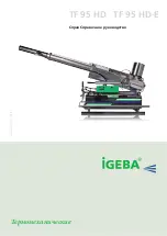
TF 95 HD
Brand: IGEBA Pages: 59
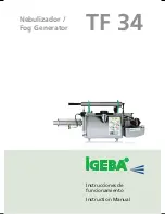
TF 34
Brand: IGEBA Pages: 48

NBA HANGTIME 40259
Brand: Midway Pages: 52

CP335B
Brand: SYSFORM Pages: 28

F-16B
Brand: XPower Pages: 12

Sewing Wizard
Brand: Mannsberger Pages: 22

ROCK-A-FIRE EXPLOSION
Brand: Creative Engineering Pages: 326

MC-35M
Brand: Magnum Pages: 11

CombBind C110E
Brand: GBC Pages: 74

MEMORYCRAFT 300E
Brand: Janome Pages: 48

MC-AT1
Brand: SAINT-FUN Pages: 12

281LY-B
Brand: Nakajima Pages: 22

3822-1/32
Brand: Pfaff Pages: 130

Smoke 400v3
Brand: Nebula Pages: 8

LH-1152-5
Brand: JUKI Pages: 12
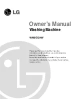
WM0532HW
Brand: LG Pages: 48
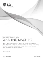
WD14030RD6
Brand: LG Pages: 44


