Panduit PTR3E, Operator And Technical Reference Manual
The Panduit PTR3E Operator and Technical Reference Manual is a comprehensive guide for users of this product, providing detailed instructions on its operation and maintenance. This essential manual is available for free download from manualshive.com, ensuring that users have all the information they need at their fingertips.
Share
Download


Reviews:
No comments
Related manuals for PTR3E
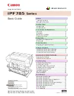
image Prograf iPF785 Series
Brand: Canon Pages: 136

A1
Brand: GBC Pages: 110

M Series
Brand: Xerox Pages: 2

TALLY MIP480
Brand: Dascom Pages: 138

T2150
Brand: Dascom Pages: 166

d-COLOR MF254
Brand: Olivetti Pages: 2

d-COLOR MF3300
Brand: Olivetti Pages: 109

d-COLOR MF3300
Brand: Olivetti Pages: 111

d-Color MF1600
Brand: Olivetti Pages: 8

mg6400 series
Brand: Canon Pages: 4

ColorWave 3800
Brand: Canon Pages: 358

PIXMA MX522
Brand: Canon Pages: 30

WorkCentre M118i
Brand: Xerox Pages: 5

X642
Brand: Lexmark Pages: 4

Bravo se Disc Publisher
Brand: Primera Pages: 58

LK-PXX
Brand: SEWOO Pages: 12

Aficio SP 3300D
Brand: Ricoh Pages: 2

8700 LDIR
Brand: Agilent Technologies Pages: 2


