background image

Before attempting to connect or operate this product, please read these 

instructions carefully and save this manual for future use. 

The model number is abbreviated in some descriptions in this manual.

This document is the Installation Guide for use in other countries except Japan.

Installation Guide

Included Installation Instructions

Network Camera

Model No.


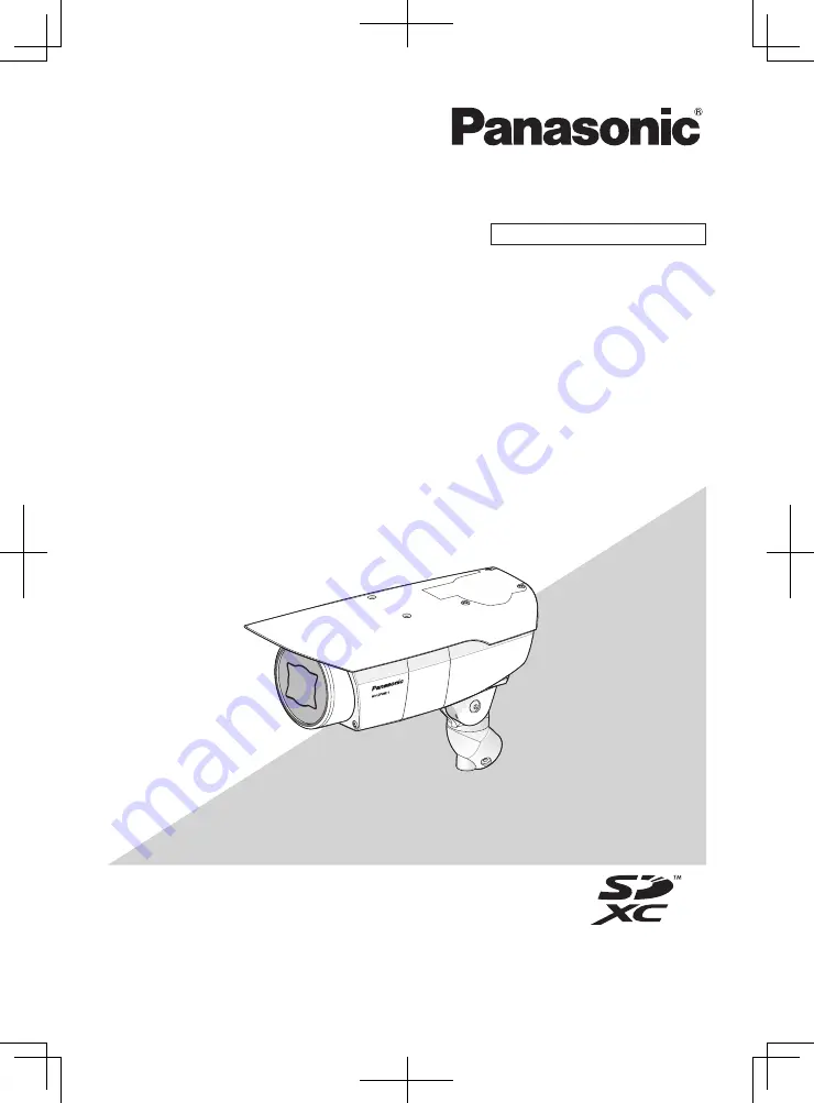
(This illustration represents WV-SPW611.)

WV-SPW631LT

WV-SPW631L

WV-SPW611L

WV-SPW611 

Summary of Contents for WV-SPW611

Page 1: ... future use The model number is abbreviated in some descriptions in this manual This document is the Installation Guide for use in other countries except Japan Installation Guide Included Installation Instructions Network Camera Model No This illustration represents WV SPW611 WV SPW631LT WV SPW631L WV SPW611L WV SPW611 ...

Page 2: ...ng the provisions of Directive 2004 108 EC Wir erklären in alleiniger Verantwortung daß das Produkt auf das sich diese Erklärung bezieht mit der folgenden Norm oder normativen Dokument übereinstimmt Gemäß den Bestimmungen der Richtlinie 2004 108 EC Nous déclarons sous notre propre responsabilité que le produit auquel se réfère la présente déclaration est conforme á la norme spécifiée ou à tout aut...

Page 3: ... security 9 Precautions 10 Precautions for installation 14 Major operating controls 16 Preparations 18 Installations Connections 19 Insert remove an SD memory card 28 Adjustment 29 Mounting the front cover 32 Attaching the mounting surface on the top surface of the camera body 33 Configure the network settings 36 Troubleshooting 38 Specifications 40 Standard accessories 47 Optional accessories 47 ...

Page 4: ...e only with the cart stand tripod bracket or table specified by the manufacturer or sold with the apparatus When a cart is used use caution when moving the cart apparatus combi nation to avoid injury from tip over S3125A 9 Unplug this apparatus during lightning storms or when unused for long periods of time 10 Refer all servicing to qualified service personnel Servicing is required when the appara...

Page 5: ...TIONS OR TROUBLES FROM UNAUTHORIZED DISASSEMBLE REPAIR OR MODIFICATION OF THE PRODUCT BY THE USER REGARDLESS OF THE CAUSE OF THE MALFUNCTION OR TROUBLE 4 INCONVENIENCE OR ANY LOSS ARISING WHEN IMAGES ARE NOT DISPLAYED DUE TO ANY REASON OR CAUSE INCLUDING ANY FAILURE OR PROBLEM OF THE PRODUCT 5 ANY PROBLEM CONSEQUENTIAL INCONVENIENCE OR LOSS OR DAMAGE ARISING OUT OF THE SYSTEM COMBINED BY THE DEVIC...

Page 6: ...LED equipped SPW631LT SPW631L SPW611L The equipped infrared LED makes it possible to take pictures at zero lx of objects as far as 30 m 98 43 feet away Equipped with 2 SD memory card slots and enhanced image recording By using 2 SD memory cards sequentially images can be recorded over long periods of time The dual recording function recording images on 2 SD memory cards simultaneously makes it pos...

Page 7: ...ory is required when using Microsoft Windows Vista Network interface 10BASE T 100BASE TX 1 port Audio interface Sound card when using the audio function Monitor Image capture size 1024 x 768 pixels or more Color 24 bit True color or better OS Microsoft Windows 8 1 Microsoft Windows 8 Microsoft Windows 7 Microsoft Windows Vista Web browser Windows Internet Explorer 11 32 bit Windows Internet Explor...

Page 8: ...eb brows ers refer to our website at http security panasonic com pss security support index html Trademarks and registered trademarks Adobe the Adobe logo and Reader are either registered trademarks or trademarks of Adobe Systems Incorporated in the United States and or other countries Microsoft Windows Windows Vista Internet Explorer ActiveX and DirectX are either regis tered trademarks or tradem...

Page 9: ...at the system is not infected by computer viruses or other malicious entities using a regularly updated anti virus program anti spyware program etc Protect your network against unauthorized access by restricting users to those who log in with an authorized user name and password Apply measures such as user authentication to protect your network against leakage or theft of information including ima...

Page 10: ...arts or screws may cause a fall of the product resulting in injury or acci dents Consult the dealer for the inspections Do not use this product in an inflammable atmosphere Failure to observe this may cause an explosion resulting in injury Avoid installing this bracket in the loca tions where salt damage occurs or corro sive gas is produced Otherwise the mounting portions will deterio rate and acc...

Page 11: ...injury or accidents Turn the power off when cleaning this product Failure to observe this may cause injury Precautions for use This product has no power switch When turning off the power disconnect the power supply from the 12 V DC power supply or the PoE device When using both the 12 V DC power supply and the PoE device for power supply disconnect both the connections To keep on using with stable...

Page 12: ...ces that vibrate images may appear distorted and stretched lengthways This phenomenon is a characteristic of image pickup devices that use CMOS sensors and is caused by the relationship between the periodic movements of the camera and the timing that the image sensor reads images This is not a prob lem with the camera To reduce the possibility of this phenomenon occurring install the camera in a s...

Page 13: ...DEO THAT WAS ENCODED BY A CONSUMER ENGAGED IN A PERSONAL ACTIVITY AND OR WAS OBTAINED FROM A VIDEO PROVIDER LICENSED TO PROVIDE AVC VIDEO NO LICENSE IS GRANTED OR SHALL BE IMPLIED FOR ANY OTHER USE ADDITIONAL INFORMATION MAY BE OBTAINED FROM MPEG LA L L C SEE HTTP WWW MPEGLA COM About the dehumidifying device This product has dehumidifying device to keep the inside at low moisture level pre ventin...

Page 14: ...turn on off the power of this product The product has no power switch When installing the product use a power supply device equipped with the ON OFF switch for servicing About the network connection When connecting to a network using the network cable of this product observe the following When wiring for the network design and engineer not to be affected by thunder It is impossible to install this...

Page 15: ...oduct in cold climates take notice of the ambi ent and internal temperatures of the product When this product is installed and operated in low temperatures below 10 C 14 F normal images may not be obtained immediately after startup In such a case wait around 2 hours or more and turn on the power again PoE Power over Ethernet Use a PoE hub device that is compliant with IEEE802 3af standard Router W...

Page 16: ...ver Sunshield Rear part of sunshield Rear cover Safety wire Tilting lock screw Network cable Alarm input output cable Power cable 12 V DC Microphone line input cable white Audio output cable black Camera mount bracket accessory RJ 45 female EXT I O terminal Panning lock screw ...

Page 17: ...it when linking Access indicator lit when accessing Auto focus AF button Initial set button WIDE button TELE button SD memory card slot SD slot 1 SD1 SD slot 2 SD2 SD memory card error indicator Auto focus indicator blinks when adjusting auto focus IR LED Lens Lens cover Packing PAL NTSC switch Monitor output jack ...

Page 18: ...e If a wall or ceiling board such as plaster board is too weak to support the total weight the area shall be sufficiently reinforced The camera mount bracket accessory can be directly mounted on the wall using a junction box locally procured embedded in the wall or a wall with a cable access hole The screws that secure the camera mount bracket on a wall are not supplied Prepare the screws accordin...

Page 19: ...wire through the camera mount bracket and secure the cam era to the camera mount bracket with the camera fixing screws x3 accessories Pass the network cable first through the camera mount bracket before passing through the other cables IMPORTANT Ensure that the camera fixing screws are firmly secured Recommended tightening torque 0 78 N m 0 58 lbf ft Camera main body Safety wire Network cable Moun...

Page 20: ...female Alarm input output cable 4P alarm cable accessory Microphone line input cable white Audio output cable black Power cable 12 V DC 2P power cable accessory 12 V DC red GND black LAN cable category 5 or better straight STP Required cable LAN cable category 5 or better straight STP 1 Connect the microphone line input cable and the microphone for use of the audio reception function Input impedan...

Page 21: ...M IN1 DAY NIGHT IN green Terminal 1 Ratings ALARM IN1 DAY NIGHT IN ALARM IN2 ALARM IN3 Input specification No voltage make contact input 4 V 5 V DC internally pulled up OFF Open or 4 V 5 V DC ON Make contact with GND required drive current 1 mA or more ALARM OUT AUX OUT Output specification Open collector output maximum applied voltage 20 V DC Open 4 V 5 V DC by internal pull up Close Output volta...

Page 22: ...camera may restart depending on the PoE hub or router used When the LAN cable is disconnected once reconnect the cable after around 2 seconds When the cable is quickly reconnected the power may not be supplied from the PoE device When cables are used outdoors there is a chance that they may be affected by lightning In this case install a lightning arrester just before where the cables connect to t...

Page 23: ... external connections in the same way Stretch the tape by approx twice see the illustration and wind it around the cable Insufficient tape stretch causes insufficient waterproofing To prevent the LAN cable hook from coming loose easily fit the Ⓙ LAN cable cover onto the pigtail cable as illustrat ed and then slide it in the direction indicated by the arrow The connector of the LAN cable used with ...

Page 24: ...ing on the monitor some characters camera title preset ID etc may not be displayed on the screen Use a switching hub or a router which is compliant with 10BASE T 100BASE TX If a PoE hub is not used each network camera must be connected to a 12 V DC power supply When using 12 V DC power supply from a PoE hub or router is not required Network camera is intended for connection to an ethernet or PoE n...

Page 25: ... box locally procured Required pull out capacity of a single screw bolt is 196 N 44 06 lbf or more TOP 6 mm W x 10 mm L 1 4 W x 3 8 L long hole 6 mm W x 10 mm L 1 4 W x 3 8 L long hole 6 mm W x 10 mm L 1 4 W x 3 8 L long hole 46 mm 1 13 16 83 5 mm 3 1 4 46 mm 1 13 16 20 mm 13 16 Cable access hole Adapter box accessory Cable access hole used for wiring The female thread for conduit is compliant wit...

Page 26: ...firmly secured Recommended tightening torque M5 1 86 N m 1 37 lbf ft Note The right or left hinges of the adapter box shall be selected so as to prevent the motion of the camera mount bracket from being interfered with by obstruc tions such as a wall when the camera mount bracket is connected to the hing es of the adapter box TOP 6 mm W x 10 mm L 1 4 W x 3 8 L long hole View from above internal Ad...

Page 27: ...h the 2 mount bracket cover screws accessories IMPORTANT Ensure that the mount bracket cover screws are firmly secured Recommended tightening torque 0 59 N m 0 44 lbf ft Mount bracket cover x2 accessories Camera mount bracket accessory Mount bracket cover screw x2 M3 x 6 accessories ...

Page 28: ...cluded in the CD ROM 1Loosen the 4 fixing screws of the front cover to remove the front cover 2 Insert an SD memory card fully into the SD memory card slot until a click is heard 3Attach the front cover to the camera page 32 4 When removing the SD memory card from the SD memory card slot detach the front cover by following step 1 and push the card until a click is heard After the SD memory card is...

Page 29: ... camera head vertically to adjust tilting 3 Tighten the panning lock screw and tilting lock screw after camera angle adjustment IMPORTANT After camera angle adjustment the panning lock screw and tilting lock screw shall be securely tightened Recommended tightening torque 2 45 N m 1 8 lbf ft Notes Use a hexagonal wrench with width across flats of 4 mm locally procured to loosen or tighten the panni...

Page 30: ...e of the view moves in the T or W direction When the angular field of view is adjusted on the TELE side optical zoom is applied until 3 2x and if there are any adjustments above this extra optical zoom is applied When the image capture size under VGA is applied the zoom factor can be adjusted up to 2x without deterioration of image quality The zooming factor is displayed on the top right of the sc...

Page 31: ...hite wall Subj with heavy flicker If the 2x extra optical zoom is applied when 1280x960 1280x720 is selected for the image capture size the image quality will be deteriorated because the effect of Extra Optical Zoom is not provided When images in the near infrared light area change from color to black white out of focus may be occurred according to the nature of optical property In this case the f...

Page 32: ... in the illustration above 1 2 3 4 twice Make sure the packing has not come off or become askew If this happens put it back into place Make sure the packing has no dust or other contaminants on it Remove any dust or contami nants on the packing Remove the cover film from the clear part of the front cover section after the installation is complete Do not touch the clear part of the front cover sect...

Page 33: ... the cap 4Rotate each cable in the direction of the arrow clockwise as illustrated and pass them between opening in the upper groove of the main body Then attach the cap to the lower groove and secure the rear cover with the fixing screw x1 Attach the rear cover to the front cover by hooking attachment hole 1 of the rear cover to the tab on the front cover while passing the protrusion of the front...

Page 34: ...ach cable and the safety wire through the camera mount bracket and connect the safe ty wire to the camera mount bracket Then bundle the wire and the cable using the cable clamp and secure them with each screw from the mounting boss to the camera mount bracket page 19 20 IMPORTANT Be sure to use the screws that were removed from the camera mount bracket Recommended tightening torque 0 78 N m 0 58 l...

Page 35: ...shield on the camera body with the 4 sunshield mounting screws after removing the sunshield backside The sunshield is attached to the camera by inserting the protrusions on the rear cover of the camera into the attachment holes on the rear part of the sunshield IMPORTANT Be sure to use the screws that were removed from the sunshield Recommended tightening torque 0 59 N m 0 44 lbf ft Fixing screw x...

Page 36: ...iguring the settings of the network 1Insert the provided CD ROM into the CD ROM drive of your PC The License Agreement will be displayed Read the Agreement and choose I accept the term in the license agreement and click OK The launcher window will be displayed If the launcher window is not displayed double click the CDLauncher exe file on the CD ROM Note Refer to Using the CD ROM in the Operating ...

Page 37: ...ess to cameras using the HTTPS function Refer to the Operating instructions on the provided CD ROM for how to con figure the HTTPS settings Click the Setup button on the Live page the user authentication window will be displayed Enter the default user name and password as follows and log in User name admin Password 12345 When changing settings related to the network settings such as connection mod...

Page 38: ...able of the camera connected using a LAN cable Check whether the connection is appro priately established Depending on the PoE device the power sup ply will stop when the demanded power exceeds its total power limit for all PoE ports Refer to the operating instructions of the PoE device in use 20 22 When the IR LED lights a part or all of the screen appears blurred Is there a wall or other reflect...

Page 39: ...with another one 22 24 AF SD ERROR indicator lights red or blinks red Isn t the write protect switch of the inserted SD memory card set to LOCK Unlock the write protect switch of the SD memory card Hasn t the inserted SD memory card been for matted on a PC Use an SD memory card formatted on the camera Or install the software to format the SD memory card on the PC Refer to our website http security...

Page 40: ...ut Applicable microphone Plug in power type Supply voltage 2 5 V 0 5 V Recommended sensitivity of microphone 48 dB 3 dB 0 dB 1 V Pa 1 kHz For line input Input level Approx 10 dBV Audio output ø3 5 mm stereo mini jack monaural output Output impedance Approx 600 Ω unbalanced External speaker with an amplifier Output level 20 dBV Waterproof 3 Main body IP66 IEC60529 Type 4X UL50 NEMA 4X compliant Dim...

Page 41: ... lx 0 00093 foot candle F1 3 Maximum shutter Off 1 30 s AGC High 0 0007 lx 0 00007 foot candle F1 3 Maximum shutter max 16 30 s AGC High SPW631LT Color 0 06 lx 0 00558 foot candle F1 6 Maximum shutter Off 1 30 s AGC High 0 004 lx 0 00037 foot candle F1 6 Maximum shutter max 16 30 s AGC High BW 0 lx 0 000 foot candle F1 6 Maximum shutter OFF 1 30 s Gain High when the IR LED is lit 0 02 lx 0 00186 f...

Page 42: ...1 4000 1 10000 Other than 2 mega pixel 16 9 60 fps mode SPW631LT SPW631L 1 3 mega pixel 16 9 60 fps mode SPW611L SPW611 OFF 1 30 3 100 3 120 2 100 2 120 1 100 1 120 1 250 1 500 1 1000 1 2000 1 4000 1 10000 Maximum shutter max 1 1000 s max 1 500 s max 1 250 s max 1 120 s max 2 120 s max 1 100 s max 2 100 s max 1 60 s max 1 30 s max 2 30 s max 4 30 s max 6 30 s max 10 30 s max 16 30 s Color BW Off O...

Page 43: ...f view SPW631LT 16 9 mode Horizontal 13 8 TELE 33 5 WIDE Vertical 7 7 TELE 18 1 WIDE 4 3 mode Horizontal 11 5 TELE 27 4 WIDE Vertical 8 6 TELE 20 1 WIDE SPW631L 16 9 mode Horizontal 30 9 TELE 105 4 WIDE Vertical 17 4 TELE 57 3 WIDE 4 3 mode Horizontal 25 8 TELE 86 4 WIDE Vertical 19 3 TELE 63 9 WIDE SPW611L SPW611 16 9 mode Horizontal 28 4 TELE 96 2 WIDE Vertical 16 1 TELE 52 8 WIDE 4 3 mode Horiz...

Page 44: ...31L 2 mega pixel 16 9 30 fps mode 2 mega pixel 16 9 60 fps mode 1920x1080 1280x720 640x360 320x180 160x90 2 mega pixel 4 3 30 fps mode 1600x1200 1280x960 800x600 VGA 400x300 QVGA 160x120 3 mega pixel 4 3 30 fps mode Used by super resolution techniques 2048x1536 1280x960 800x600 VGA 400x300 QVGA 160x120 SPW611L SPW611 1 3 mega pixel 16 9 30 fps mode 1 3 mega pixel 16 9 60 fps mode 1280x720 640x360 ...

Page 45: ...mission interval 0 1 fps 60 fps JPEG frame rate will be restricted when displaying both JPEG and H 264 images Cropping function Off JPEG 1 JPEG 2 JPEG 3 H 264 1 H 264 2 H 264 3 H 264 4 H 264 all Alarm action On Off Audio compression method G 726 ADPCM 32 kbps 16 kbps G 711 64 kbps AAC LC 2 Bandwidth control Unlimited 64 kbps 128 kbps 256 kbps 384 kbps 512 kbps 768 kbps 1024 kbps 2048 kbps 4096 kbp...

Page 46: ...rminals 1 Transmission for 4 streams can be individually set 2 AAC Advanced Audio Coding Low Complexity is only used when recording audio on an SD memory card 3 For further information about PC system requirements and precautions for when using Microsoft Windows 8 1 Microsoft Windows 8 Microsoft Windows 7 Microsoft Windows Vista or Windows Internet Explorer click Manual Open from the supplied CD R...

Page 47: ...c Mounting screws for adapter box camera mount bracket M5 x 20 mm 5 pcs of them 1 for spare Camera fixing screw M4 x 10 mm 4 pcs of them 1 for spare Mount bracket cover screw M3 x 6 mm 3 pcs of them 1 for spare LAN cable cover 1 pc 1 The CD ROM contains the operating instructions and different kinds of tool software programs 2 This label may be required for network management The network administr...

Page 48: ...ropean Union If you wish to discard electrical and electronic equipment please contact your dealer or supplier for further information Information on Disposal in other Countries outside the European Union These symbols are only valid in the European Union If you wish to discard these items please contact your local authorities or dealer and ask for the correct method of disposal Note for the batte...

Reviews: