background image

Order Number: MGCS041001C0

H21

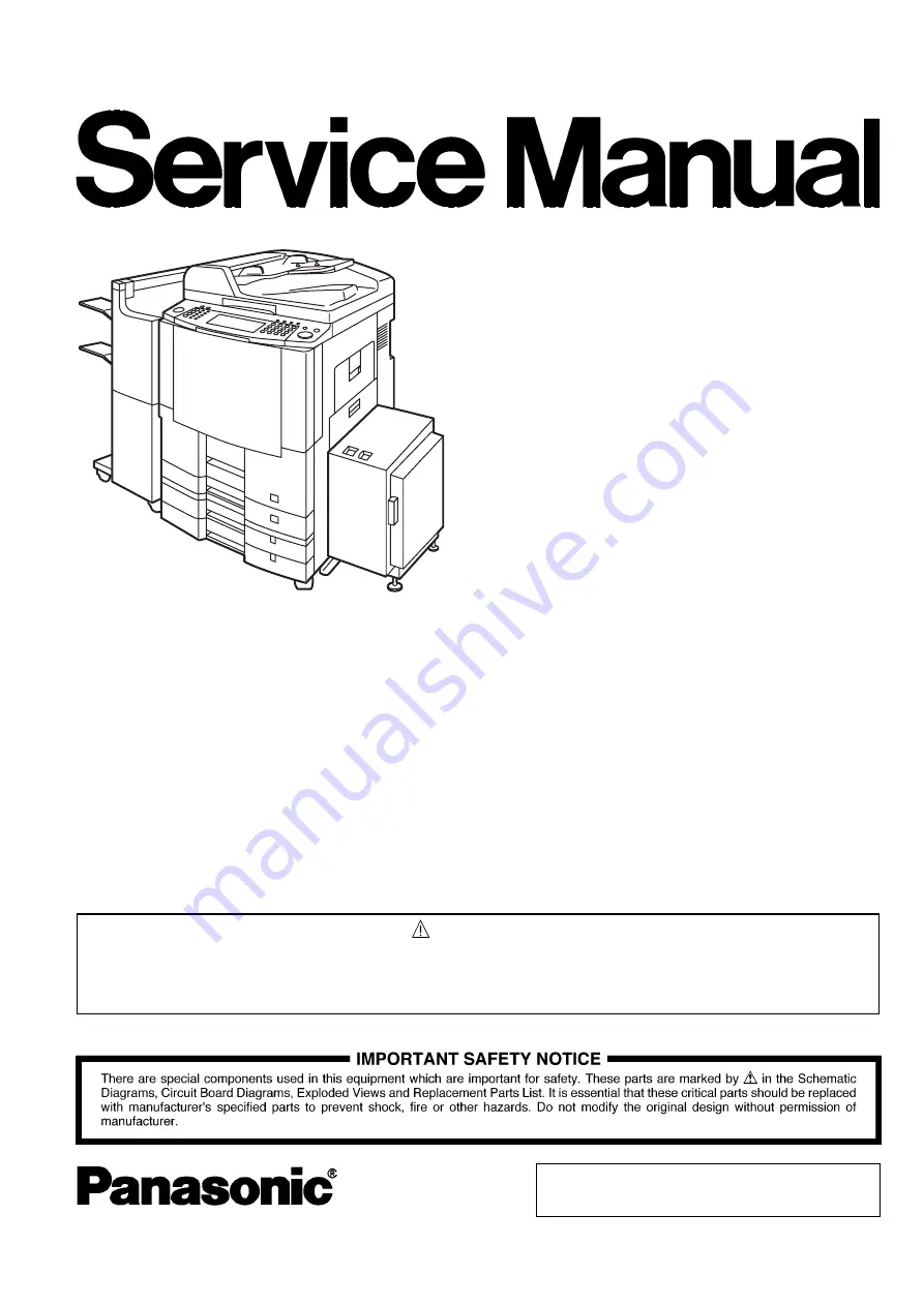
Digital Imaging Systems

DP-3510/4510/6010
DP-3520/4520/6020
DP-3530/4530/6030

[ Version 5.2 ]

This service information is designed for experienced repair technicians only and is not intended for use by the general public.
It does not contain warnings or cautions to advise non-technical individuals of potential dangers in attempting to service a product.
Products powered by electricity should be serviced or repaired only by experienced professional technicians. Any attempt to service 
or repair the product or products dealt within this service information by anyone else could result in serious injury or death.

WARNING

© 2006 Panasonic Communications Co., Ltd. 
All rights reserved. Unauthorized copying and distribution is
a violation of law. Published in Japan.

Summary of Contents for Workio DP-3510

Page 1: ...advise non technical individuals of potential dangers in attempting to service a product Products powered by electricity should be serviced or repaired only by experienced professional technicians Any...

Page 2: ...PCB Caution Pb free solder has a higher melting point than standard solder typically the melting point is 50 70 F 30 40 C higher Please use a soldering iron with temperature control and adjust it to 7...

Page 3: ...Note If the Hard Disk Drive Unit is installed to prevent a Disk Scan Function from being performed similar to when the power is abruptly interrupted to the PC it is important to follow the step sequen...

Page 4: ...4 Beispiel DP 6530 4530 6030 Hinweis...

Page 5: ...a live connector can cause arcing consequently deforming the plug and cause fire When disconnecting the machine grasp the plug instead of the cord Pulling on a cord forcibly can damage it and cause fi...

Page 6: ...authorized modification can cause smoke or fire Consumable Safeguards Never dispose of toner toner cartridge or a waste toner container into an open flame Toner remaining in the cartridge can cause an...

Page 7: ...ng a jammed paper that is difficult or impossible to see do not try to remove it by yourself Doing so can cause injuries or burns Switch Off the machine immediately and wait until it cools down Consum...

Page 8: ...imile 237 System Description 266 6 1 Copy Process 266 6 2 Precautions with Consumables 267 6 3 New Digital Image Control Qualitative Reasoning Based Adaptive Controller New Digital QUANTUM 269 6 4 Inv...

Page 9: ...nit DA SP41 403 8 32 Installing the Power Supply for Finisher DA PW600 411 8 33 Installing the Key Counter Harness Kit DZTY000128 413 8 34 Installing the Dehumidifier Heater DZTQ000041 415 8 35 Instal...

Page 10: ...anada A4 For EU A4 For Other Destinations Paper Tray LDR LGL LTR LTR R INV R For USA and Canada A3 A4 A4 R A5 R B4 FLS For EU A3 A4 A4 R B4 B5 B5 R For Other Destinations Sheet Bypass LDR LGL LTR LTR...

Page 11: ...da and EU Option Yes Standard For Other Destinations Original Set Face Up Scanning Method Sheet Through Capacity Original 70 sheets LTR A4 USA and Canada LTR 20 lb 75 g m2 Other Destinations A4 80 g m...

Page 12: ...Detection Manual Control Panel Low Level Paper Warning Empty only Dimensions W x D x H 23 6 x 28 7 x 11 4 in 600 x 730 x 290 mm Weight 66 1 lb 30 0 kg 3000 sheets Paper Feed Module Letter 3 000 sheets...

Page 13: ...he Heater Power NW Function available Auto Off Mode Yes 4W For USA Canada and EU With Finisher Power Supply NW Function not available Yes 3W For Other Destinations Without Finisher Power Supply NW Fun...

Page 14: ...tronic Sorting Yes Rotation Sorting Yes Insertion Job Cover Mode Yes Page Insertion Mode Yes OHP Interleave Mode Yes Non copy Copy Presentation Mode Yes Department Counter Yes 300 Departments i ADF Mu...

Page 15: ...et Fax Mode change LCD Main Indication Message Language Default English American For USA and Canada Specified Language For EU and Other Destinations Original Size Image Indication Yes with Image Paper...

Page 16: ...5 Optical System Original Detection Method Reflective Photo Sensor Type Scanning Method 600 dpi CCD Dehumidifier Yes Supplied as a Service Part Part Number DZTQ000041 Mechanical Multi Copy Mode No 6 P...

Page 17: ...te Container Yes Outer Tray Option For USA and Canada Yes For EU and Other Destinations Operating Instructions Yes Power Supply 1 Power Requirement 99 138 VAC 47 63 Hz Single phase 100 VAC Power Suppl...

Page 18: ...mm Transmission Std 8 x 3 85 Fine 8 x 7 7 S Fine 8 x 15 4 16 x 15 4 600dpi 600 x 600 dpi Reception Std 8 x 3 85 Fine 8 x 7 7 S Fine 8 x 15 4 16 x 15 4 600dpi 600 x 600 dpi Scanner Mechanism 1 Scannin...

Page 19: ...tack Yes Face Down 8 Consumables Toner Bottle OPC Drum and Staples Fax Memory 1 Standard Memory DP 3530 4530 6030 3 MB 180 pages DP 3510 3520 4510 4520 6010 6020 2 MB 120 pages Flash ROM ITU T Image N...

Page 20: ...irect Deferred Transmission No ADF Deferred Transmission 6 Deferred Transmission Yes Max 50 Timers 7 Deferred Multi Station Transmission Yes 8 Priority Direct Transmission Yes Priority ADF Transmissio...

Page 21: ...ary Polling Password Yes 10 Continuous Polling Yes Convenience 1 Panel Display Wide Touch Panel Display 2 Voice Contact No 3 Edit File Mode Yes With View Mode 4 Incomplete File Save Yes With View Mode...

Page 22: ...No 9 File XMT No 10 Fax Forward Yes Received File Transfer Only with Internet Fax Option 11 Sub address XMT Yes T Routing 12 Sub address RCV Yes 13 OMR XMT No Standards 1 PSTN FCC Part 68 1997 Indust...

Page 23: ...s Parallel Interface Ethernet 6 OS Win 98 Me Win NT 4 0 Win 2000 XP 7 GDI Yes 8 PDL PCL6 Yes Requires Optional PCL6 Emulation Kit 9 PDL PS3 Yes Requires Optional PS PCL6 Emulation Kit 10 Duplex Printi...

Page 24: ...ing Function 1 Scanning Device CCD i ADF Platen 2 Halftone 256 Halftone Shades With Error Diffusion 3 Max Document Size A3 Ledger 4 Scanning Resolution dpi 600 x 600 300 x 300 150 x 150 Selectable 600...

Page 25: ...e Ledger A3 2 Effective Scanning Width 11 4 in 289 mm 3 Scanning Resolution pel mm x lines mm Std 203 x 98 8 x 3 85 Fine 203 x 196 8 x 7 7 S Fine 203 x 391 8 x 15 4 406 x 391 16 x 15 4 600dpi 600 x 60...

Page 26: ...FAX Transmission Yes Requires Panafax Desktop Software Inbound Routing Yes Using Sub Address Local print available Address Book Registration from PC Yes Via Email 4 I Fax Parameters Registration via E...

Page 27: ...Electronic Sorting Board Automatic Duplex Unit Parallel Port Interface Printer 10 100 Ethernet Interface SPC PC Board DRV PC Board 550 Sheet Paper Tray 1 550 Sheet Paper Tray 550 Sheet x 1 Paper Tray...

Page 28: ...ge Memory 16 MB DA SM16B For Electronic Sorting Image Memory 64 MB DA SM64B Image Memory 128 MB DA SM28B Expansion Flash Memory Card 4 MB UE 410047 Additional Page Memory for Fax Communication Board D...

Page 29: ...stinations Please ask your sales company for details Part Name Part Number Remarks Toner DQ TU24D 24K for DP 3510 4510 DQ TU35D 35K for DP 6010 DQ TU241G 24K for DP 3520 3530 4520 4530 DQ TU351G 35K f...

Page 30: ...effect at date of manufacture For USA only Front View Right View Left View Top View Rear View 10 4 in 265 mm 12 7 in 322 mm 23 6 in 600 mm 29 8 in 758 mm 35 4 in 900 mm CAUTION THIS PRODUCT CONTAINS A...

Page 31: ...8 in 300 mm 11 in 280 mm 17 3 in 440 mm 29 8 in 758 mm 19 9 in 505 mm 23 6 in 600 mm 101 2 in 2570 mm 95 3 in 2420 mm Copier Finisher 3000 Sheet LCT LT R_LGL Adapter 83 3 in 2115 mm 3 9 in 100 mm 3 9...

Page 32: ...tters I and O For Example DP 3510 PU DP 4510 PU Production Facility Production Year Starting with Year 2001 the last 2 digits of the year is represented as A T A 01 2001 K 11 2011 B 02 L 12 C 03 M 13...

Page 33: ...33 JAN 2006 Ver 5 2 DP 3510 3520 3530 4510 4520 4530 6010 6020 6030 1 6 Control Panel DP 3510 3520 4510 4520 6010 6020 DP 3530 4530 6030 PRINT DATA STATUS ACTIVE DP 6030...

Page 34: ...Paper Feed Motor ADF Feed Motor Scanning Motor Corona Wire Cleaning Motor Ozone Fan Dust Fan Hopper Motor Main Motor Drum Motor Suction Fan Lift Motor Tray 1 Lift Motor Tray 2 Lift Motor Tray 3 Lift...

Page 35: ...ath Sensor Toner Waste Container Detection Sensor Toner Waste Container Full Detection Sensor Paper Remaining Sensor Tray 1 Paper Remaining Sensor Tray 2 Paper Remaining Sensor Tray 3 Paper Remaining...

Page 36: ...lutch Sheet Bypass ADU Registration Clutch Separator Solenoid ADF Inverting Roller Clutch1 ADF Inverting Roller Clutch2 ADF Pinch Solenoid ADF Paper Feed Roller Clutch ADF Registration Roller Clutch1...

Page 37: ...00 Sheet Tray LCT 2 2 19 i ADF 2 2 3 Hopper Unit 2 2 6 System Console 2 2 18 PC Boards 2 2 16 Toner Waste Container 2 2 2 Filters 2 2 1 Control Panel Unit 2 2 5 Paper Exit Transportation 2 2 15 Fuser...

Page 38: ...tructions 2 2 1 Filters 1 Turn the Power Switches to the OFF position 2 Disconnect the AC Power Cord 4911 3 Open the Right Cover 4 Remove 3 Screws H8 5 Remove the Right Side Rear Cover 117 6 Remove th...

Page 39: ...4520 4530 6010 6020 6030 9 Remove the Ozone Filter 2 Cover 106 10 Remove the Ozone Filter 2 107 Following steps 11 15 are not applied for USA and Canada 11 Remove 9 Screws H8 12 Remove the Rear Upper...

Page 40: ...6 Ver 5 2 DP 3510 3520 3530 4510 4520 4530 6010 6020 6030 14 Remove 2 Screws 21 15 Pull the Rear Frame 2 3910 and remove the Ozone Filter 4 4226 Note To prevent Rear Frame 2 from warping do not pull h...

Page 41: ...06 Ver 5 2 DP 3510 3520 3530 4510 4520 4530 6010 6020 6030 2 2 2 Toner Waste Container 1 Open the Right Cover 2 Remove 3 Screws H8 3 Remove the Right Side Rear Cover 117 4 Remove the Toner Waste Conta...

Page 42: ...Document Feeder i ADF Unit 1 Lift up the Original Tray Assembly 2 Clean the Exit Roller 814 3 Open the ADF Cover 4 Clean the Pickup Roller 511 Paper Feed Roller 508 Separation Roller 610 and Registrat...

Page 43: ...4530 6010 6020 6030 6 Remove the Paper Feed Roller Shaft 505 Assembly in the arrow direction 7 Remove the Paper Feed Roller 508 8 Move the Pickup Bracket 9 Remove 2 Snap Rings H7 10 Remove the Pickup...

Page 44: ...30 6010 6020 6030 12 Remove 3 Screws J9 13 Remove the Lower Opening and Shutting Guide 1 601 14 Remove the Separation Roller Assembly 15 Remove the Snap Ring H6 Note When reinstalling make sure that t...

Page 45: ...hat the Yellow Tooler s Die on the side of the roller is positioned as illustrated facing the Front Frame 18 Lift the Lower Opening and Shutting Guide 2 Assembly 19 Clean the Inverting Roller 809 with...

Page 46: ...Original Tray Assembly 27 Remove the ADF Rear Cover 627 28 Remove 1 Screw 21 29 Remove the Front ADF Cover Bracket 529 30 Release the ADF Cover Arm 624 31 Remove the ADF Cover 502 Assembly Note When...

Page 47: ...6010 6020 6030 32 Remove 1 Screw 21 33 Remove the Registration Guide 2 721 34 Clean the Registration Roller 2 818 35 Remove the Snap Ring G6 36 Remove the D8 Bearing 822 37 Remove 2 Snap Rings G6 38...

Page 48: ...Remove 2 Registration Guide Sheets 1 1119 and 2 Registration Guide Sheets 2 1120 Caution Do not remove the 3 indicated Screws Note When reinstalling the Registration Guide Sheet 1 and 2 make sure tha...

Page 49: ...g and Shutting Guide Assembly 43 Lift up the Original Tray Assembly 44 Nudge the Inverting Guide Assembly towards the right side to open it 45 Remove 2 Screws 21 46 Remove the Inverting Guide Assembly...

Page 50: ...Scanner Lamp CCD Assembly 1 Move the Scanning Lamp to the position where it can be replaced See Sect 5 1 7 F8 00 2 Remove 2 Screws H8 3 Remove the Right Platen Cover 112 4 Remove the Glass Assembly 12...

Page 51: ...rn the Inverter PC Board Case upside down 8 Disconnect 2 Harnesses on the Inverter PC Board 1209 9 Remove 2 Screws F10 10 Remove the Inverter PC Board 1209 11 Remove the Scanning Lamp 1228 Note Ensure...

Page 52: ...ve the CCD Cover 1213 14 Disconnect 2 Harnesses on the CCD PC Board CN850 and CN851 Important Before proceeding make a note of the position of the alignment pointer If the CCD is not reinstalled at th...

Page 53: ...10 6020 6030 17 Remove 2 Screws 20 18 Disconnect 2 Harnesses on the Sensors 19 Remove 2 Multi Beam Sensors 1309 20 Remove 1 Screw 20 21 Disconnect the Harness on the Sensor 22 Remove the Multi Beam Se...

Page 54: ...0 4530 6010 6020 6030 2 2 4 2 Scanning Motor 1 Remove 9 Screws H8 2 Remove the Rear Upper Cover 110 3 Remove 2 Screws 21 4 Remove the Harness Clamp 2 3501 5 Disconnect the ADF Harness 6 Open the ADF U...

Page 55: ...ove 2 Screws H8 10 Remove the Left Platen Cover 111 11 Remove 2 Screws H8 12 Remove the Right Platen Cover 112 13 Remove 2 Screws N6 14 Remove 4 Screws H8 15 Remove the Rear Platen Cover 113 16 Discon...

Page 56: ...4510 4520 4530 6010 6020 6030 2 2 5 Control Panel Unit 1 Open the Front Cover 2 Swing the Hopper Unit in the direction of the arrow as illustrated 3 Remove the Battery Holder 4 Remove 7 Screws 21 5 Re...

Page 57: ...6 Turn the Control Panel Unit upside down 7 Disconnect 4 Harnesses on the PNL1 PC Board CN220 CN221 CN222 and CN224 8 Remove 1 Screw 21 9 Disconnect 4 Harnesses on the PNL1 PC Board CN223 CN225 CN229...

Page 58: ...d CN251 13 Remove 7 Screws F10 14 Remove the PNL2 PC Board 323 15 Disconnect the Harness on the INV PC Board CN2 16 Remove 2 Screws F10 17 Remove the INV PC Board 329 18 Remove 2 Screws F10 19 Release...

Page 59: ...010 6020 6030 22 Remove 4 Screws F10 23 Remove the PNL3 PC Board 313 24 Remove 2 Screws H4 25 Remove 2 Screws H4 26 Remove the LCD Module 328 27 Remove the Touch Panel 327 Note Reinstall the Battery H...

Page 60: ...See Sect 2 2 5 2 Swing the Hopper Unit to the right side See Sect 2 2 5 3 Rotate the Toner Bottle counter clockwise and remove it 4 Clean any toner residue from the Lower Hopper Cover 1411 5 Remove 1...

Page 61: ...61 JAN 2006 Ver 5 2 DP 3510 3520 3530 4510 4520 4530 6010 6020 6030 8 Remove 2 Screws 21 9 Remove the Hopper Motor 1414...

Page 62: ...ct 2 2 5 3 Remove 1 Screw J9 4 Remove the Connector Cover 3930 5 Disconnect the Harness 6 Pull the Developer Release Lever 3823 out and turn it clockwise 7 Remove the Developer Unit 1632 8 Remove the...

Page 63: ...oper Cover 1601 Removing the old Developer and Toner 11 Install the Developer Exchange Knob 1405 12 Turn the Developer Unit upside down over a suitable container and dump the used Developer and Toner...

Page 64: ...Developer Unit 1632 with a dry soft cloth Caution Clean the Developer and Toner residue from the encircled areas thoroughly as shown in the illustrations If not properly cleaned problems related to s...

Page 65: ...ckwise 5 Loosen 1 Screw and remove the Drum Unit Note When handling the Drum Unit hold by the Handle as illustrated Caution Exercise caution not to scratch the surface of the OPC Drum Green and not to...

Page 66: ...rated 8 Remove 3 Split Lock Washers 1825 9 Remove 3 Separators 1826 by unhooking the spring as illustrated Note When installing the Separators hook the springs by using a Tweezer or a Small Screw Driv...

Page 67: ...6020 6030 12 Release 2 Latch Hooks and remove the Frame Cover 1805 13 Remove 4 Screws 21 14 Remove the Front Fixation Plate 1822 15 Turn the Front Drum Bushing 1820 counter clockwise and remove it 16...

Page 68: ...20 3530 4510 4520 4530 6010 6020 6030 18 Turn the Rear Drum Bushing 1842 clockwise and remove it 19 Remove the OPC Drum 1811 20 Remove the Blade Pressure Spring 1807 21 Remove 1 Screw 20 22 Remove the...

Page 69: ...Hooks are properly attached 23 Release 4 Latch Hooks and remove the Front and Rear Cleaning Felt 1849 1848 Assemblies Cleaning the Density Sensor 24 Clean the Density Sensor CDS PC Board 1846 with a d...

Page 70: ...530 6010 6020 6030 28 Clean the Corona Grid 1919 with a soft cloth saturated with isopropyl alcohol 29 Remove the Front and Rear Block Sheets 1911 and 1920 30 Remove the Corona Wire 1915 and the Tensi...

Page 71: ...71 JAN 2006 Ver 5 2 DP 3510 3520 3530 4510 4520 4530 6010 6020 6030 32 Clean the Corona Case 1906 with a soft cloth or a cotton swab saturated with isopropyl alcohol...

Page 72: ...ADU 1 Open the Front Cover See Sect 2 2 5 2 Swing the Hopper Unit to the right side See Sect 2 2 5 3 Turn the Lifting Lever 2327 counter clockwise 4 Pull the ADU Unit out 5 Clean the Exit Rollers A a...

Page 73: ...4520 4530 6010 6020 6030 8 Clean the Intermediate Roller 2403 9 Clean the Registration Roller 2430 10 Pull out the 1st Paper Tray 11 Remove 1 Screw 25 12 Remove the Right Lock Plate 3810 13 Remove 1 S...

Page 74: ...Registration Release Knob 2328 20 Remove 3 Screws 21 21 Remove the Inner Cover 2332 22 Remove 2 Registration Guide Springs 2409 and 2 Front Registration Springs 2413 23 Remove the Upper Registration...

Page 75: ...28 Remove 2 Snap Rings K9 29 Remove the 2 Bearings 822 30 Remove 2 Screws F10 31 Remove 2 E Rings J7 32 Remove the Intermediate Roller Gear 2621 33 Remove 2 Bearings 2603 34 Remove 2 Screws F10 35 Ope...

Page 76: ...76 JAN 2006 Ver 5 2 DP 3510 3520 3530 4510 4520 4530 6010 6020 6030 38 Remove the Registration Roller 2430 39 Remove the Intermediate Roller 2403...

Page 77: ...it to the right side See Sect 2 2 5 3 Pull out the ADU Unit See Sect 2 2 9 4 Remove the Corona Unit 2 2352 5 Remove the Front and Rear Block Sheets 2307 2303 6 Remove the Tension Spring 2339 7 Remove...

Page 78: ...78 JAN 2006 Ver 5 2 DP 3510 3520 3530 4510 4520 4530 6010 6020 6030 12 Disconnect the Harness 13 Pull out the LED PC Board 2343 14 Remove the LED Knob 2319...

Page 79: ...t to the right side See Sect 2 2 5 3 Open the Upper Exit Cover 4 Push the Release Lever 8136 down in order to free the Exit Guide 7 8126 5 Remove 2 Screws N3 6 Remove the Fuser Cover 121 7a Disconnect...

Page 80: ...3530 4510 4520 4530 6010 6020 6030 10 Release the Harnesses from Hooks 11 Remove 1 Screw L6 12 Remove the Solenoid 2012 Assembly 13 Remove 1 Screw K2 14 Remove the Solenoid 2012 15 Remove 2 Screws K1...

Page 81: ...move the Cleaning Web Roller 2007 Red 20 Remove the Cleaning Web 2003 White Note When reinstalling make sure that the Cleaning Web is spread out 21 Remove 1 Screw 25 22 Remove the Ground Plate 3 2214...

Page 82: ...4510 6010 skip to steps 33 36 27 Remove 2 Snap Rings H6 28 Remove the Upper Paper Exit Guide 2223 29 Remove 2 Screws 36 30 Remove the Upper Separator Bracket 2120 31 Remove 5 Tension Springs 2219 32...

Page 83: ...6 38 Remove 1 Screw K2 39 Remove the Rear Fuser Cover 2031 40 Remove 2 Screws 16 41 Remove 2 Fuser Lamps 2027 2028 Note 1 Do not touch the glass portion of the Fuser Lamps with bare hands Grease from...

Page 84: ...of the Jam Release Knob by turning clockwise 45 Remove the Jam Release Knob 2022 Note The Jam Release Knob and Screw are assembled 46 Remove 1 Screw K2 47 Remove the Front Fuser Cover 2021 48 Remove 2...

Page 85: ...the Lower Front Guide 2113 58 Remove 2 Screws K4 59 Remove 1 Screw K2 60 Remove the Upper Fuser Bracket 2115 61 Remove the Fuser Roller 2105 62 Remove the Fuser Roller Gear 2108 2 Fuser Roller Bearing...

Page 86: ...520 3530 4510 4520 4530 6010 6020 6030 63 Remove the Pressure Roller 2205 64 Remove 2 Pressure Roller Bearings 2204 Note Before removing note the position and or direction of the Pressure Roller Beari...

Page 87: ...LSU Cover 115 5 Remove the Right Platen Cover See Sect 2 2 4 6 Remove 2 Screws 20 7 Remove the LSU Shield Bracket 4009 8 Disconnect 3 Harnesses 9 Remove the Glass Assembly 120 See Sect 2 2 4 Importan...

Page 88: ...2006 Ver 5 2 DP 3510 3520 3530 4510 4520 4530 6010 6020 6030 10 Remove 3 Screws L1 11 Remove the LSU 4030 12 Turn the LSU upside down 13 Clean the LSU Glass with a soft cloth saturated with isopropyl...

Page 89: ...n the Right Cover 2908 2 Clean the Intermediate Rollers 3005 3010 with a soft cloth saturated with isopropyl alcohol 3 Remove 1 Screw J4 4 Remove the Right Cover 2908 5 Push the Pin and remove the Rig...

Page 90: ...4520 4530 6010 6020 6030 9 Remove the 1st Paper Feed Module 10 Remove 1 Screw 21 11 Remove the Front Feed Guide 3122 12 Remove the Bushing 2 208 and One Way Clutch 3205 13 Lift the Reverse Roller 321...

Page 91: ...ve the Pickup Roller 3211 Note When reinstalling make sure that the Latches and the Notches are aligned as illustrated 16 Remove the Snap Ring H6 17 Remove the Reverse Roller 3219 Note When reinstalli...

Page 92: ...Remove 1 Screw J4 20 Remove the 2nd Paper Feed Module Note Follow the instructions for steps 10 17 of the 1st Paper Feed Module 21 Remove the Snap Ring G6 22 Remove the 3 Intermediate Roller 3005 3010...

Page 93: ...4603 4611 3 Pull out the ADU 2351 See Sect 2 2 9 Note Ref No 2351 does not include all individual parts 4 Remove 1 Screw 25 5 Remove the Sheet Bypass 6 Remove 2 Screws 25 7 Remove the Upper Sheet Byp...

Page 94: ...Ver 5 2 DP 3510 3520 3530 4510 4520 4530 6010 6020 6030 12 Remove 4 Screws 25 13 Remove the Feed Cover 4638 Assembly 14 Remove the Snap Ring H6 15 Remove the Paper Feed Roller 4608 16 Remove the Feed...

Page 95: ...r 3 8003 4 Open the Front Cover See Sect 2 2 5 5 Open the Paper Exit Cover See Sect 2 2 11 6 Remove 4 Screws 25 7 Remove the Plate Assembly 8 Clean the Pressure Roller 8311 and Exit Roller 3 8312 with...

Page 96: ...0 2 2 16 PC Boards 1 Remove the Rear Upper Plate See Sect 2 2 4 2 2 Disconnect All Harnesses on the DRV PC Board 3 Remove 7 Screws 21 4 Remove the DRV PC Board 8601 5 Remove 4 Screws 21 6 Remove the S...

Page 97: ...ove 6 Screws 21 9 Remove the SC PC Board 8401 10 Remove 2 Screws 11 Remove the PRT PC Board 8402 12 Remove 5 Screws H8 13 Remove 1 Screw M5 14 Remove the Rear Lower Cover 108 15 Remove the Toner Waste...

Page 98: ...0 6030 17 Remove 5 Screws 21 18 Remove the SPC PC Board 8501 19 Remove 3 Screws 21 20 Remove NFL PC Board 8603 Assembly 21 Disconnect 2 Harnesses on the NFL PC Board CN132 and CN133 22 Remove 2 Screws...

Page 99: ...030 25 Remove 4 Screws 21 26 Remove the Paper Exit Motor 8127 Assembly 27 Disconnect 3 Harnesses 28 Open the Front Cover See Sect 2 2 5 29 Pull out 1st Paper Tray 30 Remove 2 Screws 21 31 Remove the L...

Page 100: ...ses on the DC PC Board CN141 CN142 CN143 CN144 and CN145 35 Remove 2 Screws 21 36 Remove the DC PC Board 8701 37 Remove 7 Screws 21 38 Remove the Heat Sink 3311 39 Remove 6 Screws 21 40 Remove the LVP...

Page 101: ...510 4520 4530 6010 6020 6030 43 Pull out the ACD PC Board 8704 Assembly 44 Disconnect the Harness on the ACD PC Board CN102 45 Disconnect 2 Harnesses on the ACD PC Board CN103 and CN104 46 Remove 6 Sc...

Page 102: ...ove the Rear Upper Plate See Sect 2 2 4 2 3 Remove the Rear Lower Plate and SC Cover Bracket See Sect 2 2 16 4 Disconnect All Harnesses on the SC PC Board See Sect 2 2 16 5 Loosen 5 Screws 21 6 Remove...

Page 103: ...10 4520 4530 6010 6020 6030 11 Remove 2 Screws 21 12 Remove the Fan 4219 Assembly 13 Remove 2 Screws 20 14 Remove the Fan 4221 Assembly 15 Remove 2 Screws H8 16 Remove the Rear Cover 9301 17 Remove 4...

Page 104: ...it See Sect 2 2 5 21 Pull out the ADU 2351 and Drum Unit 1852 Note Ref No 2351 and 1852 do not include all individual parts 22 Remove the Fuser Cover See Sect 2 2 11 23 Remove 1 Screw 24 24 Pull out F...

Page 105: ...10 4520 4530 6010 6020 6030 29 Remove the Pin 2743 30 Remove 2 Screws 21 31 Move the Harness Bracket 3525 32 Disconnect the Harness on the Toner Waste Sensor 33 Disconnect the Harness on the HVPS CN10...

Page 106: ...3510 3520 3530 4510 4520 4530 6010 6020 6030 35 Remove 3 Screws 21 36 Remove the HVPS Bracket 3611 37 Remove 5 Screws 21 38 Remove the HVPS 8705 39 Remove 1 Screw 21 40 Remove the Belt Cover 2824 41...

Page 107: ...4510 4520 4530 6010 6020 6030 42 Disconnect 2 Harnesses 43 Remove 3 Screws 21 44 Remove the Fan Assembly 45 Disconnect 8 Harnesses 46 Release the Harnesses from 7 Clamps 47 Remove 13 Screws 25 48 Rem...

Page 108: ...6020 6030 50 Remove the Drum Drive Shaft 2704 51 Remove 4 E Rings J7 and K5 2 Snap Rings G6 2 Pins 2840 and 6 Gears 2806 x 2 2808 2833 2834 and 2835 52 Remove 11 Screws 21 53 Remove the Drum Drive Pla...

Page 109: ...109 JAN 2006 Ver 5 2 DP 3510 3520 3530 4510 4520 4530 6010 6020 6030 56 Disconnect the Harness and release it from the Clamp 57 Remove 2 Screws M3 58 Remove the DC Brower 4220...

Page 110: ...2 2 18 System Console 2 2 18 1 3rd 4th Paper Feed Module 1 Open the Release Cover 9324 2 Clean the Intermediate Roller 3010 3 Remove 1 Screw H8 4 Remove the Right Side Rear Cover 9319 5 Remove 1 Scre...

Page 111: ...ove 1 Screw J4 9 Remove 3rd Paper Feed Module Note Follow the instructions for steps 10 17 of the 1st Paper Feed Module 10 Remove the 4th Paper Feed Module by following the steps for the 3rd Paper Fee...

Page 112: ...8 2 Remove the Rear Cover 9301 3 Disconnect the Harness on the System Console Drive Motor 4 Remove 4 Screws J4 5 Remove 1 Screw 21 6 Remove the Drive Motor 9410 7 Release the Harness from 2 Clamps 8 D...

Page 113: ...e 6 Screws 21 13 Remove 2 Lift Motor 2 4023 Assemblies 14 Release the Harness from the Clamp 15 Remove 2 Screws 5M 16 Remove the Lift Motor 2 4023 17 Disconnect all Harnesses on the CST PC Board 18 Re...

Page 114: ...510 4520 4530 6010 6020 6030 2 2 19 3000 Sheet Tray LCT 1 Remove 2 Screws 21 2 Remove the Front Guide 9142 3 Clean the Feed Roller 9129 4 Remove the Snap Ring H6 5 Remove the Feed Roller 9129 6 Remove...

Page 115: ...e Guide Bracket 9112 10 Remove the Pickup Roller 9107 11 Remove 3 Screws J3 12 Remove the Reinforcement Bracket 9101 13 Remove the Paper Feed Roller 9111 14 Disconnect All Harnesses on the LCT PC Boar...

Page 116: ...Note Screw See Note Screw See Note Screw See Note Screw See Note Screw See Note Screw See Note XTB3 6FFJ XYN3 F8FJ XTB4 8FFJ XYN4 F6FJ XYN3 F6FJ XYN4 F8FJ 21 23 25 XTB4 10FFJ 51 35 36 XYN3 F5FJ 3F 24...

Page 117: ...rew See Note Screw See Note Shoulder Screw See Note Screw See Note Screw See Note Screw Screw Screw Screw Screw Screw Screw Screw Screw XTT4 8HFN J2 Silver Screw XTB4 8HFJ XTB4 10GFJ J4 J3 FFPFA01632...

Page 118: ...crew See Note Shoulder Screw See Note Screw See Note Screw Screw Screw Screw Screw Screw XTB3 10GFJ XTB3 6GFJ J5 J9 FFPFA01071 XSN3 W8FJ TP XYN4 F16FJ FFPFA01761 FFPFA01771 Black Shoulder Screw Should...

Page 119: ...crew See Note Screw See Note Screw See Note Screw See Note Screw Screw Screw Screw Screw Screw Screw Screw Screw Screw Screw Screw E Ring E Ring XUC9VM L2 XYA3 FF6FJ M5 XTW3 8GFJ XTW4 12LFJ XTB26 6H M...

Page 120: ...ew See Note Screw See Note Screw See Note Screw See Note Screw Screw Screw Screw Screw Screw Screw Screw Screw Screw Screw Screw XTB4 10FFJ XTN3 12FFJB Blue Screw XTN5 10FFJ FFPFA01591 FFPFA01611 Shou...

Page 121: ...ew See Note Screw See Note Screw See Note Screw See Note Screw Screw Screw Screw Screw Screw Screw Screw Screw XTW4 10PFJ P9 XYA4 FF10 Q1 XSB26 4FJ Q3 FFPFA0068B Shoulder Screw Q4 XTT4 8HFN Q5 XSB3 12...

Page 122: ...of Rollers Rollers should be cleaned with water and cloth Use of IPA Isopropyl alcohol should be used sparingly 3 Precautions for Disassembly and Adjustment Turn the Main Power Switch on the Back and...

Page 123: ...r when servicing the photocopier take the following precautions 1 Do not insert into the path of the laser any screwdrivers or other tools that have high reflectance properties 2 Before servicing the...

Page 124: ...re the RAM DATA with the previously printed one 2 Auto Document Feeder ADF Check Clean 1 Clean the Rollers and Separation Rubber with Isopropyl Alcohol when required 3 Scanner Unit Check Clean 1 Clean...

Page 125: ...3530 4510 4520 4530 6010 6020 6030 3 3 Preventive Maintenance Points 6 5 7 8 9 10 57 58 A 17 45 49 48 47 25 2 52 52 52 11 12 3 22 23 16 18 1 B 4 56 54 55 50 51 52 53 43 50 51 61 59 60 53 50 51 53 50...

Page 126: ...126 JAN 2006 Ver 5 2 DP 3510 3520 3530 4510 4520 4530 6010 6020 6030 DETAIL A DETAIL B 37 33 34 31 35 39 404142 32 38 29 30 36 13 14 15...

Page 127: ...Roller 816 120K Water 1 11 Inverting Roller 809 120K Water 1 12 Exit Roller 814 120K Water 1 Hopper Unit 13 Toner Bottle Holder 1402 480K Water 1 Refer to Sect 2 2 6 F7 02 Total Count 14 Toner Bottle...

Page 128: ...6030 2205 480K 41 Pressure Roller DP 3510 3520 3530 2232 480K 42 Pressure Roller Bearing DP 3510 3520 3530 2233 480K Automatic Duplex Unit 43 Intermediate Roller 2403 120K Water 1 Refer to Sect 2 2 9...

Page 129: ...nce Refer to Section 3 3 and 3 4 2 Press the FUNCTION ORIGINAL SIZE LEDGER A3 and 3 keys simultaneously in that order to enter the Service Mode 3 Enter the Copy Service Mode F5 70 PM cycle and change...

Page 130: ...e Container Indicators Upon detecting that the Toner Waste Container is full the machine will complete the current job and stop operating A blinking Maintenance and Toner Waste Container Indicators wi...

Page 131: ...n the SC PCB is 4 MB Two 2 Optional Expansion 8 MB Program Memory FRM8 PCB can be installed into SLOT 1 and SLOT 2 The Firmware to be written into the 4 MB onboard the 8 MB of SLOT 1 SLOT 2 depend upo...

Page 132: ...e saved in this Board The Firmware is transferred as Serial Data from SC PCB D SPC PC Board Firmware The 512 KB Program Memory F ROM is mounted on the SPC PCB as a standard The Programs for Scanner Co...

Page 133: ...ols NwFirmup NwFirmup OI pdf Refer to the Network Firmware Update Tool OI on the CD Setup xFirmware Tools NwFirmup Setup Setup exe 2 Preparing the Firmware Code Double click the appropriate Destinatio...

Page 134: ...occurs please refer to the next section Updating through the Parallel Port and use the Local Firmware Update Tool to recover the unit 4 The suffix _xx for the Folder Name or File Name may not exist d...

Page 135: ...than factory default 3 6 4 Updating the Firmware using the Master Firmware Card 1 Before starting print the F5 F6 Parameters Copier Lists 2 Turn the Main Power Switch on the back of the unit not the s...

Page 136: ...he Power Switch on the left side and the Main Power Switch on the back of the machine to the OFF position See 3 6 7 2 Insert the Flash Memory Card 4 MB or 8 MB into the machine 3 Turn the Main Power S...

Page 137: ...y Card is erased machine prompts Update Program Card Press NO 7 Press STOP first and then press FUNCTION CLEAR keys simultaneously to return to standby 8 Turn the Power Switch on the left side and the...

Page 138: ...Firmware Update Tool to update the firmware to the required level If the unit does not boot up properly follow the steps below 1 Turn the power Off use the power switch on the back of the unit not th...

Page 139: ...er a AU b English French Spanish g German French Italian Division Soft When it is divided into a and b SFDM PNL A A V1xxxx PU Destination Code Copier PU USA Canada PB UK Destination Code Fax AU USA Ca...

Page 140: ...al Model Number etc a AU b English French Spanish g German French Italian Division Soft When it is divided into a and b MMK2 PNL A A Vxxxxx PU Destination Code Copier PU USA Canada PB UK Destination C...

Page 141: ...l Model Number etc a AU b English French Spanish g German French Italian Division Soft When it is divided into a and b M25R PNL A A Vxxxxx PU Destination Code Copier PU USA Canada PB UK Destination Co...

Page 142: ...6 7 Replace Exposure Lamp Platen Glass OPC Drum 1 8 Developer 1 9 OPC Drum Developer 1 1 1 2 2 2 3 4 10 Corona Unit 11 Drum Unit 1 12 Toner Density Sensor 1 13 TDC Sensor 1 2 3 3 4 2 3 4 5 3 4 2 3 1 2...

Page 143: ...as Voltage of the Developer DP 35xx 250 300 copies DP 45xx 150 200 copies DP 60xx 50 100 copies 2 Ensure that Ledger A3 Size Paper is loaded in one of the Trays and pull out the remaining trays includ...

Page 144: ...gray scale P N FQ SJ1011 and verify the density as shown below If it is within specification skip to step 10 a Gray scale 1 should not be visible b Gray scale 2 should be clearly visible 5 Press the R...

Page 145: ...not be visible b Gray scale 2 should be clearly visible 5 Press the RESET key to exit the F2 Mode 6 Press the 6 and START keys to enter the F6 Mode Adjust Parameters 7 Enter F6 55 Mode T P Mode Contr...

Page 146: ...nd change the tray setting to the appropriate paper size Empty or pull out all the remaining trays including the bypass tray to disable them 2 Press the FUNCTION ORIGINAL SIZE LEDGER A3 and 3 keys sim...

Page 147: ...the following procedures during PM 1 Make sure that the LAN cable is disconnected before performing F8 09 2 Make sure that paper is set in any paper tray before performing F8 09 3 After performing F8...

Page 148: ...l display 8 When the Power Switch is turned ON After the Power Switch is turned On 9 At 100 prints after the Power Switch was turned ON Upon reaching the specified number of prints 2 10 When the Auto...

Page 149: ...machine to the ON I position and continue holding the keys for approximately 30 seconds until the Display becomes stable The LCD Display starts blinking and shows a on the upper left edge of the disp...

Page 150: ...throughcorrectly Does the recording paper exit the unit Troubleshoot printed copy quality problems Troubleshoot the Document Feeder Check for recording paper path problems TroubleshootImproper LCDDis...

Page 151: ...rouble resolved Replace the Low Voltage Power Supply Unit Is the trouble resolved Check connectors CN52 SC PCB and CN220 PNL1 PCB Is LED LCD displayed Does the display appear normal Replace the LCD Mo...

Page 152: ...CB normal Is the OPC Drum Developer Unit operational Replace the OPC Drum Developer Unit 1 Check all connectors and voltages on the PS 3 Replace the PS 2 Check the contacts between PS and Developer Un...

Page 153: ...ge Wire with a soft dry cloth 2 Replace the Charge Unit 1 Check all connectors and voltages on the PS 2 Check the Spring Connector and voltage on the PS 3 Replace the PS Are there any foreign particle...

Page 154: ...t dry cloth 2 Replace the Corona Unit Yes No Clean or replace the rollers Yes No Check the Scanner mechanism No Yes Yes Is the recording paper damp Is the OPC Developer Unit operational 1 Remove the p...

Page 155: ...essure Roller surfaces clean No Yes Is the recording paper damp Are there any foreign particles or stains in the Corona Unit No Yes Yes No Replace the recording paper Replace the OPC Developer Unit 1...

Page 156: ...here any foreign particles or stains in the Corona Unit Yes No Replace the OPC Developer Unit 1 Clean the Corona Wire with a soft dry cloth 2 Replace the Corona Unit Is the LSU normal No Yes Replace t...

Page 157: ...eveloper Unit operational No Yes Is the LSU normal No Yes Replace the LSU Is the HVPS normal 1 Check all connectors and voltages on the HVPS 2 Check the Spring Connector and voltage on the HVPS 3 Repl...

Page 158: ...es Is the recording paper damp Yes No Replace the recording paper Replace the OPC Drum Developer Unit Is the PS normal 1 Check all connectors and voltages on the PS 2 Check the Spring Connector and vo...

Page 159: ...x Service Mode 3 normal Check the Scanner mechanism Reset the Developer Unit as shown in the Illustration below No Yes Is the OPC Developer Unit operational Is the recording paper damp Yes No Replace...

Page 160: ...aper damp Yes No Replace the recording paper Replace the OPC Drum Developer Unit Is the PS normal 1 Check all connectors and voltages on the PS 2 Replace the PS Yes No 1 Clean the Charge Wire with a s...

Page 161: ...sing Printed image does not bond to the paper Note Replace the entire Fuser Unit when the Thermostat and or the Thermistor turn into an open circuit END Is the Fuser Unit normal No Yes Replace the Fus...

Page 162: ...paper damp Replace the recording paper Is the OPC Drum Developer Unit operational Yes No Replace the OPC Drum Developer Unit P Paper Travel Are the Fuser and Pressure Roller surfaces clean END No Yes...

Page 163: ...ny foreign particles or stains in the Fuser Unit 2 Clean or replace the rollers 1 Remove any foreign particles and or clean the stains Are there any foreign particles or stains in the paper path Yes N...

Page 164: ...ceiving test with the reference fax unit Is the printed copy correct Yes No Make a local copy No Yes Check the connections of CN850 851 on the CCD PCB CN 55 56 on the SC PCB the Scanning Lamp Is the r...

Page 165: ...0 3520 3530 4510 4520 4530 6010 6020 6030 4 3 15 Document Skewing END START Is the LSU normal Check the Scanner mechanism Check or replace LSU No No Yes Yes Is the Test Pattern printout in Copier F1 M...

Page 166: ...es No Yes No Replace with correct paper Replace with the Panasonic Toner Are all switches and sensors operating properly Do the rollers rotate properly Yes No Are there any foreign particles or paper...

Page 167: ...g Rollers dirty Are there any foreign particles or paper pieces in the scanning area Yes No Remove the foreign particles or paper pieces from the scanning area No Yes Is the scanning area dirty 1 Clea...

Page 168: ...or to verify the proper information Check the power switch cables and the current settings of unit Does the Default Gateway respond to the ping IP command Ask the Network Administrator to check the De...

Page 169: ...ent layers As with all networking TCP IP works better when its plugged in therefore start your troubleshooting by checking the Physical Connectivity first the cable s In our examples we ll use several...

Page 170: ...is a command line tool included with every Microsoft TCP IP client any DOS or Windows client with the TCP IP protocol installed PING is a simple utility that is used to send a test packet to a specif...

Page 171: ...168 3 254 with 32 bytes of data Reply from 192 168 3 254 bytes 32 time 5ms TTL 253 Reply from 192 168 3 254 bytes 32 time 4ms TTL 253 Reply from 192 168 3 254 bytes 32 time 4ms TTL 253 Reply from 192...

Page 172: ...out b To determine whether a router is slow and needs to be upgraded or additional routers should be installed on the network You can determine this by simply comparing the time it takes for a packet...

Page 173: ...imple route that took only a single hop When another network is added as the number of hosts grows it gets complicated and the systems on the most distant networks cannot communicate When the router r...

Page 174: ...llowing output A Address Record in Domain From the DOS command line type Is t A Domain Name to display the following output To leave from this menu type exit on the command line C WINDOWS route print...

Page 175: ...and line to bring up the Telnet screen Then click on the Terminal menu and on Preferences check the Local Echo and Block Cursor radio dials and click on the OK button Click on the Connect menu then cl...

Page 176: ...ected 5 LVPS is defective 6 SPC PCB connector is disconnected 7 SPC PCB is defective U6 Close Right Cover 1 Right Cover is open 2 Right Cover Sensor is disconnected 3 Right Cover Sensor is defective 4...

Page 177: ...connected 3 ADF Sensor is defective U30 Close Punch Cover 1 Punch Cover is open 2 Punch Cover Sensor is disconnected 3 Punch Cover Sensor is defective U31 Remove Paper in Saddle Unit 1 Paper Jam in th...

Page 178: ...is installed turn the Power Switch on the Left Side of the machine to the OFF position first After wating approximately 10 seconds turn the Main Power Switch on the Back of the machine to the OFF pos...

Page 179: ...nsor ADU Entrance Sensor Registration Sensor Timing Sensor Paper Path Sensor 2nd Paper Path Sensor 1st Paper Path Sensor Intermediate Roller Sensor ADU Intermediate Sensor ADU Exit Sensor Fuser Unit P...

Page 180: ...h Sensor does not go off within a predetermined time after the Paper Path Sensor is activated B J13 The 3rd Paper Path Sensor does not go off within a predetermined time after the Paper Path Sensor is...

Page 181: ...keeps detecting paper within a predetermined time during non printing mode C D J60 1 The Finisher Registration Sensor does not detect paper within a predetermined time after Exit Sensor is activated 2...

Page 182: ...ON after a predetermined time has lapsed C B J99 No VSNC Signal within a predetermined time after VRDY Signal is activated C DP 3520 3530 4520 4530 6020 6030 DP 3510 4510 6010 Contents Section J70 J7...

Page 183: ...ive 5 Scanning Mechanism is defective 6 DRV PCB connector is disconnected 7 DRV PCB is defective 8 SPC PCB connector is disconnected 9 SPC PCB is defective 10 LVPS is defective E1 20 Laser Unit horizo...

Page 184: ...connector is disconnected 6 Lift Motor is defective 7 Lower Limit Sensor connector is disconnected 8 Lower Limit Sensor is defective 9 LCT PCB connector is disconnected 10 LCT PCB is defective 11 LVP...

Page 185: ...ted with Toner E3 20 Main Motor rotation 1 Drive Mechanism is defective 2 Main Motor connector is disconnected 3 Main Motor is defective 4 DRV PCB connector is disconnected 5 DRV PCB is defective 6 SP...

Page 186: ...onnected 2 Cleaner Home Position Sensor 1 is defective 3 Cleaner Home Position Sensor 2 connector is disconnected 4 Cleaner Home Position Sensor 2 is defective 5 Cleaner Motor Drive Mechanism is defec...

Page 187: ...s disconnected 9 HTC PCB is defective E4 02 Paper Jam 1 Paper Jam in Fuser Unit 2 Paper Exit Sensor 1 or 2 is disconnected 3 Paper Exit Sensor 1 or 2 is defective 4 DRV PCB connector is disconnected 5...

Page 188: ...SPC PCB is defective 3 IPC PCB is disconnected 4 IPC PCB is defective 5 Finisher Interface Cable is disconnected 6 OP LVPS connector is disconnected 7 OP LVPS is defective 8 DC PCB connector is disco...

Page 189: ...titch Communication E7 41 Finisher Saddle Positioning Plate Motor E7 42 Finisher Saddle Folding Motor E7 43 Finisher Saddle Guide Motor E7 44 Finisher Saddle Alignment Motor E7 45 Finisher Saddle Rear...

Page 190: ...0 6010 6020 6030 E13 Out of Toner Code Function Check Points E13 Toner Sensor 1 Toner Bottle is not installed correctly 2 Out of Toner 3 Toner Sensor is disconnected 4 Toner Sensor is defective 5 SPC...

Page 191: ...occurred SC PCB 331 XMT C 8 minutes timer error Germany only 400 XMT B T1 timer 35 5 sec elapsed without detecting 300 bps signal Wrong number is dialed and the START button is pushed Telephone line...

Page 192: ...poor line quality and receiving operator requests voice contact Receiver is defective Modem MJR PCB etc FXB PCB or MJR PCB is defective 410 RCV D Received DCN while waiting for post command EOP MPS EO...

Page 193: ...Received relay transfer request or confidential document to distribute to an end receiving station or all confidential mailboxes are used 457 RELAY XMT CONF XMT POLL B Remote unit does not have Relaye...

Page 194: ...requested by RX side 570 RCV B Password or machine code did not match during remote diagnostic communication 571 XMT B Remote unit did not have the remote diagnostic function 580 XMT B Sub address tr...

Page 195: ...t SMTP Server IP Address is set No email application is activated on the Mail Server 717 XMT LAN Incomplete SMTP Protocol transmission Mail Server s hard disk may be full Mail Server is defective 718...

Page 196: ...N The machine was requested to relay a document but has no Relay Hub capability 814 Conf XMT Conf Polling Relay Comm PSTN The remote station does not have Relay XMT nor Confidential Communication capa...

Page 197: ...it Manufacturer Code Not used defined Fax Diagnostic Codes Data Definition Manufacturer Code 0 1 Casio 2 Canon 3 Sanyo 4 Sharp 5 Tamura 6 Toshiba 7 NEC 8 Oki 9 Hitachi A Xerox B Fujitsu C Matsushita D...

Page 198: ...d Received 7 Received Received Received 8 Pressed 9 Received Pressed A Received Pressed B Received Received Pressed C Received Pressed D Received Received Pressed E Received Received Pressed F Receive...

Page 199: ...line Fine D Fine E Fine F 0 ms line Fine Fax Diagnostic Codes Data Definition Deferred Comm Dialing RCV Memory Non Memory 0 Manual Communication Non Memory 1 Used Manual Communication Non Memory 2 Aut...

Page 200: ...es XMT Off Off 4 RCV On Off 5 Yes RCV On Off 6 XMT On Off 7 Yes XMT On Off 8 RCV Off On 9 Yes RCV Off On A XMT Off On B Yes XMT Off On C RCV On On D Yes RCV On On E XMT On On F Yes XMT On On Fax Diagn...

Page 201: ...ck Call 3 4 Memory Transfer 5 6 7 8 Yes 9 Report XMT Yes A Check Call Yes B Yes C Memory Transfer Yes D Yes E Yes F Yes Fax Diagnostic Codes Data Definition Short Protocol Standard Non Standard 0 Stan...

Page 202: ...d defined Fax Diagnostic Codes Data Definition Coding ECM 0 MH 1 MR 2 MMR 3 JBIG 4 5 6 7 8 MH Yes 9 MR Yes A MMR Yes B JBIG Yes C Yes D Yes E Yes F Yes Fax Diagnostic Codes Data Definition Symbol Rate...

Page 203: ...inition Modem Speed Modem Speed V 34 0 2400 bps 1 4800 bps 2400 bps 2 7200 bps 4800 bps 3 9600 bps 7200 bps 4 TC 7200 bps 9600 bps 5 TC 9600 bps 12000 bps 6 12000 bps 14400 bps 7 14400 bps 16800 bps 8...

Page 204: ...nic Device Increase the Page Margins in the application The Panasonic Device requires minimum margins of inches 5 mm on all sides The font type is incorrect Check if the selected font is installed in...

Page 205: ...e an error is found in the current printer setting Verify and specify the paper size or orientation to coincide with the application and the printer driver settings Error Message The available Sort Me...

Page 206: ...vice Mode Item Function F1 Self Test 00 CCD Test This test is used for checking the CCD 01 LCD LED Test This test is used for checking the LCD and LEDs 02 Page Memory Test This test is used for checki...

Page 207: ...ICE F5 66 Interleaving default Blank F5 17 Paper size tray4 sys2 None F5 67 Page insertion default Blank F5 18 Paper size L LCT LETTER F5 68 Cover mode default F Blank F5 19 F5 69 Reduce N in 1 space...

Page 208: ...UMENT FEEDER iADF Yes 3rd PAPER FEED MODULE Yes 4th PAPER FEED MODULE Yes LCT Yes FINISHER FS605 PUNCH UNIT Yes FAX BOARD Yes NETWORK SCANNER Yes PCL PRINTER Yes PS PRINTER Yes IPX SPX Yes EMAIL Yes D...

Page 209: ...eloper count 295 Corona cleaning count 295 Ave print drum rise up 0 Total opc rotation time 0 Ave sec drum rise up 0 F7 03 Paper feed count Sheet bypass count 147 1st Paper tray count 90 2nd Paper tra...

Page 210: ...put Check No Function Condition Message Display Remarks 7 6 5 4 3 2 1 0 000 Paper Path Sensor Paper is detected 0 Intermediate Roller Sensor Paper is detected 0 Fuser Unit Paper Exit Sensor Paper is d...

Page 211: ...Path Sensor 1st Paper Tray Paper is detected 0 Upper Limit Sensor 1st Paper Tray Upper Limit is detected 1 NP Sensor 1st Paper Tray Paper is not detected 1 Paper Remaining Sensor 3 1st Paper Tray Sens...

Page 212: ...Container Detection Sensor Toner Waste Container is detected 0 Suction Fan Lock Signal Normal 0 008 Power Supply Fan Lock Signal Normal 0 Ozone Fan 2 Lock Signal Normal 0 Exhaust Fan 3 Lock Signal Nor...

Page 213: ...Sensor LCT Paper is detected 0 012 Paper Remaining Sensor 3 LCT Sensor is activated 1 Paper Remaining Sensor 2 LCT Sensor is activated 1 Paper Remaining Sensor 1 LCT Sensor is activated 1 013 Upper P...

Page 214: ...on Sensor Home position is detected 1 Punch Unit Sensor Punch Unit is detected 0 018 Rocking Guide Open Sensor Guide is open 1 Shutter Open Sensor Shutter is open 1 Tray Unit Home Position Sensor Home...

Page 215: ...Detecting Signal 24V Line is OFF 1 022 029 Not Used 030 ADF B1 Sensor Original is detected 1 ADF B2 Sensor Original is detected 1 ADF B3 Sensor Original is detected 1 ADF Inverting Sensor Original is...

Page 216: ...st Fan 3 rotates 057 Power Supply Fan When CN758 12 is 24V Power Supply Fan rotates 058 Not Used 059 Separator Solenoid When CN764 2 signal level changes to 0V from 24V solenoid operates 060 Mg Roller...

Page 217: ...to 0V from 5V motor rotates 080 Paper Feed Roller Clutch 4th Paper Tray When CN608 3 signal level changes to 0V from 24V clutch operates 1 minute 081 Paper Feed Solenoid 4th Paper Tray When CN608 4 si...

Page 218: ...y 109 Tray Elevator Unit Test 1 Tray moves to Upward direction 2 Bin Finisher FS600 2 Bin Saddle Stitch Finisher FS605 and 2 Bin Finisher FS330 110 Tray Elevator Unit Test 2 Tray moves to Home Positio...

Page 219: ...4 signal level changes to 0V from 24V clutch operates for 3 seconds 168 ADF Registration Roller 2 Clutch When CN656 2 signal level changes to 0V from 24V clutch operates for 3 seconds 169 ADF Invertin...

Page 220: ...and touch the OK button When the C CLEAR key is touched the selected code input will not be accepted Press FUNCTION and C CLEAR keys simultaneously to exit the service mode Reboot the machine after s...

Page 221: ...tch Printing Mode From March 2004 MP 0 Off 1 On 1 09 Fuser Lamp Control 0 Off 1 Auto 0 for USA Canada 1 for Europe 10 11 Not Used 12 Printer Fan Extension 0 None 2 2 min 5 5 min 5 13 Paper Out Red Ind...

Page 222: ...pe 19 Not Used 20 ADF 0 No 1 Auto 1 21 Finisher 0 No 1 Auto 1 22 System Console 0 No 1 Auto 1 23 LCT 0 No 1 Auto 1 24 QUANTUM TDC Adj Level 0 No 1 Low 2 Medium 3 High 1 From July 25 Digital QUANTUM 0...

Page 223: ...for Other Destinations 1 41 Count Up Timing 0 At feed 1 At exit 1 42 KEY DEPT Counter 0 No 1 Key Cnt 2 DEPT 3 Card 0 43 Key Counter Timing Same as F5 41 0 44 Insert Paper Count 0 No 1 Yes 0 45 Dept Co...

Page 224: ...30 mm 1 58 Toner Waste Container Full Alarm 0 Stop 1 3 K 2 5 K 3 8 K 4 10 K 2 59 Add Toner Alarm 0 Stop 1 Continue 0 60 Auto Tray Selection 0 No 1 Yes 1 61 62 Not Used 63 U13 Clear 0 Any keys 1 Func 1...

Page 225: ...nue 1 Stop 1 73 PM Fuser Web 0 120 K 1 240 K 1 74 Fuser Web Feeding 0 1 10 1 1 20 2 1 30 1 75 76 Not Used 77 Text Error Diffusion 0 Errordif 1 Multilvl 0 78 A4 LTR Size Select 0 No 1 Yes 0 79 Not Used...

Page 226: ...size for Manual Skyshot Mode M1 and M2 70 x 160 92 M2 Size 95 x 220 93 94 Not Used 95 Paper Size FA Factory use only 0 Japan 1 USA CAN 2 Europe 3 Other 1 for USA Canada 2 for Europe 96 Bypass Detecti...

Page 227: ...position when scan is made 9 9 0 1 01 Adjust read mag l t Adjustment of ratio for parallel position when scan is made 9 9 0 1 02 100 selection Adjustment from 99 1 to 100 9 9 9 0 1 03 Original regist...

Page 228: ...6 26 19 5mV 27 Bias Frequency Factory use only AC Bias frequency adjustment 2 2 1KHz 28 Quantum white density Adjustment of standard white density level Should not be adjusted in the field and must be...

Page 229: ...99 99 53 CCD read position adj Adjustment of CCD read position 42 44 0 2mm 54 T mode contrast 127 127 55 T P mode contrast 127 127 56 P mode contrast 127 127 57 Sep DC Volt 1 Sided Compensation of De...

Page 230: ...top position Adjustment of ADF reverse stop position 99 99 0 3mm 87 ADF exhaust stop position Adjustment of ADF exit stop position 99 99 0 3mm 88 ADF feed regist 1 sided Adjustment of ADF pick up for...

Page 231: ...D Code Key Operator s identification code for access to the counter mode 02 Maintenance Count 00 Total Count Total count for all copies prints 01 PM Count Preventive Maintenance count 02 Scanner PM Co...

Page 232: ...Count Total count of A4 R Letter R Print 09 A3 Ledger Count Total count of A3 Ledger Print 10 B4 Legal Count Total count of B4 Legal Print 04 Scanner Count 00 ADF Count Total count of originals fed t...

Page 233: ...ed b To return the optical system to the home position press the CLEAR key 01 05 Not Used 06 Error Log Print View a Each time the arrow button is pressed the machine errors or paper jam codes stored i...

Page 234: ...numerical key input Note The locking operation is automatically reset when the Power switch is turned ON again 20 TDC sensor output adj Adjustment of TDC sensor 21 Not Used 22 LSU PWM Pattern 3 Factor...

Page 235: ...mber when a machine malfunction occurs 02 Firmware Version 00 SC Displays the firmware version for SC 01 SC boot Displays the firmware version for SC Boot 02 PNL Displays the firmware version for PNL...

Page 236: ...he firmware in the machine with the Parallel Port 08 Program Backup Refer to Sect 3 6 00 Main Onboard F ROM 4MB 01 Option 1 all Slot 1 FRM8 PCB 8MB 02 Option 1 a Slot 1 FRM8 PCB 4MB a 03 Option 1 b Sl...

Page 237: ...vice Mode Table The following service modes are provided to assist you in setting operational functions of the unit and determining the condition of the unit No Service Mode Description 00 Not Used 01...

Page 238: ...AL Start to TX automatically 001 ALARM STATUS 1 OFF 2 Timer 6 sec 3 Constant Selects the No Paper or No Toner alarm status OFF Alarm is disabled Timer Alarm will shut off after 6 seconds Constant Alar...

Page 239: ...the following suffix Destinations The Fax Firmware is automatically loaded with the Host Firmware PB UK PF France PG Switzerland PK China PM Germany PT Taiwan PU USA PEU UK 006 ID DISPLAY 1 Number Num...

Page 240: ...C7200 9600 7200 4800 2400 bps Note This parameter is applicable only when communicating with regular G3 machines When communicating with Super G3 V 34 machines use Parameter No 33 019 ITU T V 34 1 Off...

Page 241: ...00 2800 2400 sr Press V or to select the symbol rate 035 V34 RX SYMBOL RATE 2400 3429sr Selects receiving symbol rate for V 34 3429 3429 3200 3000 2800 2400 sr Press V or to select the symbol rate 036...

Page 242: ...ept for USA and Canada 1 Off 2 On Selects whether to detect Dial Tone before dialing the telephone number 057 DC LOOP CHECK Except for USA and Canada 1 Off 2 On Selects whether the unit checks the DC...

Page 243: ...PIN Available if No 73 Error Detect is set to RATE See Note 2 072 CONTINUOUS ERROR 1 Off unlimited 2 3 lines STD 3 6 lines STD 4 12 lines STD Selects the continuous total error criteria of Off 3 6 or...

Page 244: ...f original registration detection timing 103 TRAIL EDGE READ TIMING 9 0 Adjustment of trail edge void 104 109 Not Used 110 MAC ADDRESS Indicates the MAC Address 111 Not Used 112 INSERT EMAIL TXT 1 Off...

Page 245: ...ror Transmit condition of RTP PIP or RTN PIN Note 4 The default setting of parameters depends on the country s specifications or regulations Print the Function Parameter List to confirm the default se...

Page 246: ...ment File Protocol Trace and the Toner Order Form 5 2 4 1 Function Parameter List A list of all Function Parameters can be printed by the following procedure Select the 03 Print Param List Report on t...

Page 247: ...L 0dB 0dB 064 015 065 016 066 017 TX START 14400bps 14400bps 067 018 RX START 14400bps 14400bps 068 NYSE FAX FORWARD Off Off 019 ITU T V 34 On On 069 NYSE LOCAL PRINT Inc Inc 020 ITU T ECM On On 070 L...

Page 248: ...t Param List Report on the Touch Panel display Select the 03 Page Memory Test on the Touch Panel display Touch the YES button to print a test pattern Touch the OK button 3 times Press FUNCTION and C C...

Page 249: ...OK button 3 times Press FUNCTION and C CLEAR keys simultaneously to exit the service mode PRINTER REPORT DATE MMM dd yyyy TIME 19 02 LAST PRINT ERROR MMM dd yyyy 15 38 J00 00 00000016 CUSTOMER ID 123...

Page 250: ...cument files from the Flash Memory Select the 03 Print Param List Report on the Touch Panel display Select the 05 All Document Files on the Touch Panel display Touch the YES button to print All Docume...

Page 251: ...ton to print a Protocol Trace Report Touch the OK button 3 times Press FUNCTION and C CLEAR keys simultaneously to exit the service mode PROTOCOL LOG REPORT DATE MMM dd yyyy TIME 16 56 STATUS OK MODE...

Page 252: ...printed out manually by the following procedure Select the 03 Print Param List Report on the Touch Panel display Select the 07 Toner Order Form on the Touch Panel display Touch the YES button to prin...

Page 253: ...DP 3520 3530 4520 4530 DQ TU35D DP 6010 DQ TU351G DP 6020 6030 The order number s may differ depending on the Model and the Destination TONER BOTTLE ORDER FORM The toner supply in your machine is run...

Page 254: ...the 04 MODEM Tests on the Touch Panel display Select the 01 Binary Signal on the Touch Panel display Select the desired parameter on the Touch Panel display and touch the CLOSE button Touch the OK bu...

Page 255: ...procedure Select the 04 MODEM Tests on the Touch Panel display Select the 02 Tonal Signal on the Touch Panel display Select the desired parameter on the Touch Panel display and touch the CLOSE button...

Page 256: ...isplay Select the desired parameter on the Touch Panel display and touch the CLOSE button Touch the OK button 3 times Press FUNCTION and C CLEAR keys simultaneously to exit the service mode DTMF Singl...

Page 257: ...3000 sr 19200 bps 47 V34 3000 sr 19200 bps 06 V34 2400 sr 14400 bps 27 V34 3000 sr 21600 bps 48 V34 3429 sr 16800 bps 07 V34 2400 sr 16800 bps 28 V34 3000 sr 24000 bps 49 V34 3429 sr 19200 bps 08 V34...

Page 258: ...lization Table No Initialize Mode Description 01 Parameter Initialize Restores the Fax and Function Parameters to default values Note Turn the Power Switch to the OFF and back to the ON position to en...

Page 259: ...ch the OK button 3 times Press FUNCTION and C CLEAR keys simultaneously to exit the service mode 5 2 7 2 Printer Reports Conditions under which a report can be printed or transmitted 1 Manual Print Th...

Page 260: ...ervice Alert Report M Maintenance Alert Report Error Code Log Tx Report Remarks Ex xx O S Refer to the Mechanical Error Code E Code Table Sect 4 5 3 E13 O Out of Toner Jxx O Refer to the Jam Error Cod...

Page 261: ...t 0 OPC Drum Count 13 B4 LEGAL Count 0 Process Unit Count 13 ADF PM Count 1 F7 04 ADF Count 1 Fuser Web Count 240986 ADF Read Count 1 Developer Count 13 Scanner Count 9 Corona Cleaning Count 13 Scanne...

Page 262: ...ion 4 Transmission Reception Copy Print Counters 5 Serial Number DP 3520 3530 4520 4530 6020 6030 Only DATE MMM dd yyyy TIME 12 00 MAINTENANCE ALERT REPORT LAST PRINT ERROR MACHINE IS RUNNING OUT OF T...

Page 263: ...510 DQ TU241G DP 3520 3530 4520 4530 DQ TU35D DP 6010 DQ TU351G DP 6020 6030 The order number s may differ depending on the Model and the Destination TONER BOTTLE ORDER FORM The toner supply in your m...

Page 264: ...R Count 0 OPC Drum Count 13 B4 LEGAL Count 0 Process Unit Count 13 ADF PM Count 1 F7 04 ADF Count 1 Fuser Web Count 240986 ADF Read Count 1 Developer Count 13 Scanner Count 9 Corona Cleaning Count 13...

Page 265: ...1 Send RCV D File The display changes to the Fax Mode Select the desired Fax number Press START key to send the Fax After the transmission the machine returns to the Stand by Mode Note If the File is...

Page 266: ...amp Transfer Separation Fusing Cleaning Primary Charge Image Exposure Developing Drum Surface Approximately 750V DC Charge Corona Drum Latent Charge Image Illumination Magnetic Doctor Blade Gap 0 6 0...

Page 267: ...pill toner or developer on a table or floor when adding toner or developer in the developer unit discard what was spilled Such supplies may damage the drum as well as cause other image problems 3 Do n...

Page 268: ...n the skin should be washed off with soapy water Toner stuck on clothing must be removed while in a dry state with a vacuum cleaner brush or by beating then by washing with soapy water Wiping off with...

Page 269: ...roved with additional Sensors Parameters and Software The following diagram illustrates this New System Control Point High Density Ideal Curve Middle Density Printer Density Data 255 0 0 35 1 3 Image...

Page 270: ...lso controlled with the Long Run Operation Compensation Parameter activated by the Timer Counter 2 every 1k sheet interval 3 Developer Compensation The Toner Density is also controlled with Developer...

Page 271: ...ton is pressed the ADF Motor 1 925 starts to rotate and drive the Pickup Roller 511 The 1st original is fed into the Paper Feed Roller 508 and the Separation Roller 610 with the Torque Limiter Assembl...

Page 272: ...se rotation of the ADF Motor 1 925 pulls the original back around the Registration Roller 1 817 and proceeds to scan the Back side of the original 3 Eject by Reverse Rotation After the Back is scanned...

Page 273: ...SW ACNRLB AC Power Supply ACSW Fuser Relay ADCLK FIFO Clock ADFRRSN1 Registration Sensor 1 Signal ADUCRRSN ADU Intermediate Sensor Signal ADUINSN ADU Sensor Signal ADURRSN ADU Registration Sensor Sign...

Page 274: ...l Clamp Switch Signal BMA Toner Bottle Motor A Clock BMAB Toner Bottle Motor AB Clock BMB Toner Bottle Motor B Clock BMBB Toner Bottle Motor BB Clock BPSN Toner Bottle Position Sensor Signal CDSN1 Den...

Page 275: ...Control Signal EXFM2 Exit Fan 2 Control Signal EXFM3 Exit Fan 3 Control Signal EXSN Paper Exit Sensor Detection Signal FULP1 AC Power Supply FULP2 AC Power Supply FULP3 AC Power Supply GND Ground GOPS...

Page 276: ...al LCLUM1 Lift Motor Control Signal 1 LCLUM2 Lift Motor Control Signal 2 LCMA Motor A Signal LCMAB Motor AB Signal LCMB Motor B Signal LCMBB Motor BB Signal LCRRSN Paper Path Sensor Signal LCSDSN Set...

Page 277: ...l nADFSES ADF Document Detect nATT Attention Signal nAUTFD Auto Feed Signal nCTON Ring Detection Signal nDUACK ADU Printer ACK Signal nDUPRNT ADU Print Request Signal nERROR Error Signal nFAXRST FAX B...

Page 278: ...Original Size Sensor Signal 1 ORSIZ3 Original Size Sensor Signal 2 ORSIZ4 Original Size Sensor Signal 3 ORSIZ5 Original Size Sensor Signal 4 OZFL2 Ozone Fan Lock Detection Signal OZFM2 Ozone Fan Contr...

Page 279: ...PMB Paper Feed Motor B Signal PMBB Paper Feed Motor BB Signal PMCLK Polygon Motor Clock PMCNT Polygon Motor Control Signal PMLOCK Polygon Motor Lock Signal PNLDO1 Panel F ROM Rewrite Serial Data PNLS...

Page 280: ...paration Solenoid Control Signal SH A Sample Hold Signal A SH B Sample Hold Signal B SIZE1SN Original Size Sensor 1 Detection Signal SIZE2SN Original Size Sensor 2 Detection Signal SIZE3SN Original Si...

Page 281: ...ning Sensor a Signal Upper ZNSN1b Paper Remaining Sensor b Signal Upper ZNSN1c Paper Remaining Sensor c Signal Upper ZNSN2a Paper Remaining Sensor a Signal Lower ZNSN2b Paper Remaining Sensor b Signal...

Page 282: ...eight of the machine options not included is as follows DP 3510 3520 3530 283 lb 128 5 kg with the i ADF pre installed DP 4510 4520 4530 6010 6020 6030 290 lb 131 5 kg with the i ADF pre installed 3 T...

Page 283: ...8 in 300 mm 11 in 280 mm 17 3 in 440 mm 29 8 in 758 mm 19 9 in 505 mm 23 6 in 600 mm 101 2 in 2570 mm 95 3 in 2420 mm Copier Finisher 3000 Sheet LCT LT R_LGL Adapter 83 3 in 2115 mm 3 9 in 100 mm 3 9...

Page 284: ...g with the i ADF pre installed To prevent injuries use the appropriate number of personnel and the proper equipment to lift or move the machine Contents List Note 1 The part number may differ dependin...

Page 285: ...the opened position to avoid the possibility of damaging the Pressure Rollers OPC Drum Do Not turn the Power Switches ON before unlocking the Pressure Roller OPC Drum 7 3 1 Installation Procedure 1 Op...

Page 286: ...Blue Screw removed in step 4 into the 2nd Paper Tray as illustrated 6 Open the Front Cover 7 Swing the Hopper open 180 8 Remove the Protective Tape from the Battery 9 To unlock the Pressure Roller tu...

Page 287: ...Release Lever Clockwise 90 15 Remove the Developer Unit 16 Release 3 Latch Hooks and remove the Upper Developer Cover 17 Shake the bottle of developer thoroughly approx 30 seconds 18 Pour the appropri...

Page 288: ...Cord into the wall outlet and turn the Main Power Switch on the Back and the Power Switch on the Left Side of the machine to the ON position Note Perform the following adjustments after the machine h...

Page 289: ...Switch Off until the adjustment cycle stops Refer to the Sequence Chart below 3 Press the STOP key 4 Press the 6 key to enter the F6 Mode 5 Write the contents of F6 21 26 and 65 on the memory sheet in...

Page 290: ...t Chart 53 54 with gray scale P N FQ SJ1011 and verify the density as shown below If it is within specification skip to step 10 a Gray scale A should not be visible b Gray scale 2 should be clearly vi...

Page 291: ...ion There will never be a need for 2 of these even if there are other options such as fax added Before proceeding it is important to determine the Final Configuration of your machine in order to corre...

Page 292: ...e CD ROM to the Firmware Data Folder in your PC Note that the files in the Archive will be extracted automatically into the designated folder when the Archived file exe is Double clicked Example From...

Page 293: ...CD ROM only Please refer to the following Operating Instructions to install the Local Firmware Update Tool Operating Instructions xFirmware Tools Firmup FIRMUP OI pdf Refer to the Local Firmware Updat...

Page 294: ...re code the display may become garbled however it will return to normal upon completion of the firmware update 3 Please refer to the service manual for additional details 4 The suffix _xx for the Fold...

Page 295: ...on There will never be a need for 2 of these even if there are other options such as fax added Before proceeding it is important to determine the Final Configuration of your machine in order to correc...

Page 296: ...Firmware Data Folder in your PC Note that the files in the Archive will be extracted automatically into the designated folder when the Archived file exe is Double clicked Example From Destination Sho...

Page 297: ...CD ROM only Please refer to the following Operating Instructions to install the Local Firmware Update Tool Operating Instructions xFirmware Tools Firmup FIRMUP OI pdf Refer to the Local Firmware Updat...

Page 298: ...become garbled however it will return to normal upon completion of the firmware update 3 Please refer to the service manual for additional details 4 The suffix _xx for the Folder Name or File Name may...

Page 299: ...will never be a need for 2 of these even if there are other options such as fax added Before proceeding it is important to determine the Final Configuration of your machine in order to correctly iden...

Page 300: ...he Firmware Data Folder in your PC Note that the files in the Archive will be extracted automatically into the designated folder when the Archived file exe is Double clicked Example From Destination S...

Page 301: ...CD ROM only Please refer to the following Operating Instructions to install the Local Firmware Update Tool Operating Instructions xFirmware Tools Firmup FIRMUP OI pdf Refer to the Local Firmware Updat...

Page 302: ...may become garbled however it will return to normal upon completion of the firmware update 3 Please refer to the service manual for additional details 4 The suffix _xx for the Folder Name or File Nam...

Page 303: ...en 5 Screws 2 Remove the Rear Plate as illustrated 3 Install the Hardware Key into one of the three available connectors CN67 CN68 or CN69 on the SC PC Board Note The connectors are keyed to prevent d...

Page 304: ...o the Installation Instruction of the Program Expansion Board DA EM600 2 Install the Hardware Key by following the steps below CAUTION Turn the Power Switch on the Left Side and the Main Power Switch...

Page 305: ...on the SC PC Board Note The connectors are keyed to prevent damage to the SC PC Board install the Hardware Key as illustrated Do not force the Hardware Key into the connector if facing the wrong way 4...

Page 306: ...Instruction of the Program Expansion Board DA EM600 2 Install the Hardware Key by following the steps below CAUTION Turn the Power Switch on the Left Side and the Main Power Switch on the Back of the...

Page 307: ...ard Note The connectors are keyed to prevent damage to the SC PC Board install the Hardware Key as illustrated Do not force the Hardware Key into the connector if facing the wrong way 4 Proceed with t...

Page 308: ...ruction of the Program Expansion Board DA EM600 2 Install the Hardware Key by following the steps below CAUTION Turn the Power Switch on the Left Side and the Main Power Switch on the Back of the mach...

Page 309: ...or if facing the wrong way 4 Proceed with the installation of other options If finished close and secure the Rear Plate and reinstall remaining Covers 5 Plug the AC Power Cord into the wall outlet and...

Page 310: ...d DA EM600 2 Install the Hardware Key by following the steps below CAUTION Turn the Power Switch on the Left Side and the Main Power Switch on the Back of the machine to the OFF position and then unpl...

Page 311: ...are keyed to prevent damage to the SC PC Board install the Hardware Key as illustrated Do not force the Hardware Key into the connector if facing the wrong way 4 Proceed with the installation of other...

Page 312: ...Hardware Key by following the steps below CAUTION Turn the Power Switch on the Left Side and the Main Power Switch on the Back of the machine to the OFF position and then unplug the AC Power Cord befo...

Page 313: ...event damage to the SC PC Board install the Hardware Key as illustrated Do not force the Hardware Key into the connector if facing the wrong way 4 Proceed with the installation of other options If fin...

Page 314: ...rdware Key by following the steps below CAUTION Turn the Power Switch on the Left Side and the Main Power Switch on the Back of the machine to the OFF position and then unplug the AC Power Cord before...

Page 315: ...th the installation of other options If finished close and secure the Rear Plate and reinstall remaining Covers 5 Plug the AC Power Cord into the wall outlet and turn the Main Power Switch on the Back...

Page 316: ...ws 2 Remove the Rear Plate as illustrated 3 Install the Hardware Key into one of the three available connectors CN67 CN68 or CN69 on the SC PC Board Note The connectors are keyed to prevent damage to...

Page 317: ...llation Instructions DZSM000782 This document 1 Loosen 5 Screws 2 Remove the Rear Plate as illustrated 3 Install the Hardware Key into one of the three available connectors CN67 CN68 or CN69 on the SC...

Page 318: ...NS600 is already installed remove it first 2 If the Firmware version installed on the machine is SC SFDM_MK2AxV30700 PNL MMK2_PNLAxV30000 SPC SFDM_SPCAxV30100 or older it must be updated for this opti...

Page 319: ...13 2 Installation CAUTION Turn the Power Switch on the Left Side and the Main Power Switch on the Back of the machine to the OFF position and then unplug the AC Power Cord before beginning installatio...

Page 320: ...ft Side of the machine to the ON position 6 Update the firmware of the unit Refer to the Service Notes 7 Execute Parameter Initialize by following the steps below a Press the FUNCTION ORIGINAL SIZE LE...

Page 321: ...e c Press 00 FAX Service Mode d Press 06 RAM Initialize e Press 03 Auto Dial Clear and the Yes button for Initialize Then press Yes button for Address Book 1 000 stations Wait approximately 2 minutes...

Page 322: ...ss Book f When the 200 station Fax Address Book file is displayed save the data file by clicking on File Save As and type the file name of your choice i e 200 Station g Then click the OK button 2 Chan...

Page 323: ...on the Back of the machine to the OFF position and then unplug the AC Power Cord before beginning installation Qty Description Part No Remarks 1 FXB PC Board See Note 1 MJR PC Board Assembly See Note...

Page 324: ...ctive tab on the Left Rear Cover for the LINE connection If installing an External Telephone remove the Lower protective tab as well 10 Attach the Line Label to the Left Rear Cover as illustrated 11 R...

Page 325: ...hine by inserting the Hooks into the slots on the frame 17 Secure the MJR PC Board Assembly with 5 Screws Short 18 Remove 1 Screw from the SC PC Board 19 Install the SDRAM Bracket into the machine and...

Page 326: ...the G3 Fax PC Board with 3 Screws Short 26 Connect the Harness to 3 Connectors on the FXB PC Board CN391 CN392 and CN393 27 Proceed with the installation of other options If finished close and secure...

Page 327: ...arness to Stamp Solenoid 37 Secure the Stamp Solenoid with 1 Screw Long 38 Reinstall the Lower Exit Guide removed in Step 35 39 Install the Stamp Assembly 40 Reinstall the all parts removed in above s...

Page 328: ...The Fax Firmware is automatically loaded with the Host Firmware PB UK PF France PG Switzerland PK China PM Germany PT Taiwan PU USA PEU UK Note For other destinations set the Function Parameter 005 De...

Page 329: ...nable the parameter settings 46 Verify the position of the stamp on the document If it is not within the desired location at the bottom of the document you can adjust its position by following the ste...

Page 330: ...e c Press 00 FAX Service Mode d Press 06 RAM Initialize e Press 03 Auto Dial Clear and the Yes button for Initialize Then press Yes button for Address Book 1 000 stations Wait approximately 2 minutes...

Page 331: ...ss Book f When the 200 station Fax Address Book file is displayed save the data file by clicking on File Save As and type the file name of your choice i e 200 Station g Then click the OK button 2 Chan...

Page 332: ...and then unplug the AC Power Cord before beginning installation Qty Description Part No Remarks 1 Hard Disk Drive HDD See Note 1 DC PCB Assembly DZHP007347 1 HDD Bracket DZJE001046 1 HDD2 Harness DZF...

Page 333: ...6030 5 Remove 4 Screws 6 Remove the Frame 7 Open the Right Cover 8 Remove 3 Silver Screws 9 Remove the Right Rear Cover 10 Remove the Toner Waste Container Note Connect the HD Harness to the HDD as i...

Page 334: ...n the SC PC Board as illustrated 17 Remove the Screw from the frame and secure the HD Harness Clamp with this Screw as illustrated Note Ensure that the clamp is around the shielded portion of the Harn...

Page 335: ...machine writes the closing status onto the Hard Disk Drive Unit 3 Turn the Main Power Switch on the Back of the machine to the OFF position This interrupts all the power to the machine 4 Unplug the A...

Page 336: ...F9 Mode Unit Maintenance c Press 00 FAX Service Mode d Press 06 RAM Initialize e Press 03 Auto Dial Clear and the Yes button for Initialize Then press Yes button for Address Book 1 000 stations Wait...

Page 337: ...ss Book f When the 200 station Fax Address Book file is displayed save the data file by clicking on File Save As and type the file name of your choice i e 200 Station g Then click the OK button 2 Chan...

Page 338: ...ally to enter the F5 42 KEY DEPT Counter 5 Select the DEPT and then OK buttons to activate the Key Dept Counter function 6 Press the STOP key Note The factory default setting for the Key Operator ID C...

Page 339: ...Manual 8 17 2 Installation Install the DD Software into the PC with the Operating Instructions by following the prompts of the Installation Wizard Qty Description Part No Remarks 1 DD Server Software...

Page 340: ...ort NH 7 1 Installation Instructions DZSM000756 This document 1 Loosen 5 Screws 2 Remove the Rear Plate as illustrated 3 Install 2 PC Board Supporters for the Slot 1 on the SC PC Board 4 Install the P...

Page 341: ...n Part No Remarks 1 Image Memory DZEC102306 16 MB DZEC101919 64 MB DZEC102307 128 MB 1 Installation Instructions DZSM000757 This document 1 Loosen 5 Screws 2 Remove the Rear Plate as illustrated 3 Ins...

Page 342: ...t Side and the Main Power Switch on the Back of the machine to the OFF position and then unplug the AC Power Cord before beginning installation Qty Description Part No Remarks 1 Image Memory UE 410047...

Page 343: ...rt No Remarks 1 System Console See Note 1 Screw M3 x 6 See Note Included inside the Paper Tray 1 Installation Instructions PJQRC0045Z This document 1 Open the 4 Handle Covers and swing the Handles upw...

Page 344: ...the speed by following the steps below 1 Remove 2 Silver Screws 2 Remove the Lower Rear Cover 3 Remove 2 Snap Rings 4 Remove the Belt 2 Gears and 2 Plastic Washers 5 Turn both Gears over and reinstal...

Page 345: ...TOP key 7 Press the FUNCTION and C CLEAR keys simultaneously to exit the Service Mode 8 Make a copy to verify your adjustment repeat the steps above if further adjustment is required Note The Gear Com...

Page 346: ...No Remarks 1 System Console See Note 1 Screw M3 x 6 XTB3 6F Included inside the Paper Tray 1 Installation Instructions DZSM000509 This document 1 Open the 4 Handle Covers and swing the Handles upward...

Page 347: ...djust the speed by following the steps below 1 Remove 2 Silver Screws 2 Remove the Lower Rear Cover 3 Remove 2 Snap Rings 4 Remove the Belt 2 Gears and 2 Plastic Washers 5 Turn both Gears over and rei...

Page 348: ...Press the FUNCTION and C CLEAR keys simultaneously to exit the Service Mode 8 Make a copy to verify your adjustment repeat the steps above if further adjustment is required Note The Gear Combination S...

Page 349: ...the Back of the machine to the OFF position and then unplug the AC Power Cord before beginning installation Qty Description Part No Remarks 1 3000 Sheet Tray LCT See Note 1 Paper Guide DZJF000543 1 Ra...

Page 350: ...ll the Rail Assembly 6 Secure the Rail Assembly with 2 Screws M4 x 10 7 Install the LCT on the Rail Assembly Note Make sure 2 Latches fit into 2 Guide Pins of the Rail Assembly in Front and Rear 8 Sec...

Page 351: ...ent repeat the steps above if further adjustment is required 10 Connect the LCT Cable to the machine 11 Connect the System Console Cable to the LCT 12 Install the Harness Clamp PLWS4 on the Rear Cover...

Page 352: ...ower Cord before beginning installation Note Make sure that the Paper Table is at the bottom Position Qty Description Part No Remarks 2 Paper Guide DZJA001020 1 Rear Guide Plate B DZJA001116 1 Front G...

Page 353: ...the Door Lock Lever onto the Door Large 9 Remove 2 Screws 10 Remove Front and Rear Guide Plate A 11 Install the Lower Support Plate 12 Secure with 4 Screws 13 Install the Guide Plate A onto the Paper...

Page 354: ...te Insert the Paper Guide into the lower desired paper size slot of the Base Unit first then hook to the upper slot in the Mechanical Assembly 17 Install the Legal Tray 18 Secure the Paper Table with...

Page 355: ...llustrated 22 Secure the Plates with 4 Screws 23 Install the Door Large onto the Mounting Pins 24 Secure with 1 Screw 25 Place a sheet of paper and close the Door Large 26 Turn the Power Switches On 2...

Page 356: ...4 Reinstall the Sensor Assy at the Legal position 35 Secure with 1 Screw 36 Reinstall the Top Cover 37 Reinstall the Front Cover 38 Attach the Paper Size Label as illustrated Note See Installation Ins...

Page 357: ...embly DZHP006490 1 Exit Roller E Assembly DZHP007040 For USA and Canada only 1 Exit Roller Gear 1 Black DZLF000639 For USA and Canada only DP 35xx 1 Stop Plate DZJL000333 1 Stop Plate 2 DZJL000334 2 S...

Page 358: ...ep 11 9 Remove the E Ring and Exit Roller Gear 1 White 10 Install the Exit Roller Gear 1 Black and E Ring included with this kit 11 Install the Exit Roller E Assembly included with this kit and secure...

Page 359: ...ecure it with 1 Screw as illustrated 18 Install the Stop Plate 2 and secure it with 1 Screw as illustrated 19 Secure the Upper Exit Cover Stopper with 1 Screw removed in step 16 above 20 Close the Upp...

Page 360: ...her See Note 2 Tray 4G1 0772 000 1 Inlet Guide 4F1 2122 000 1 Latch Plate 4G1 5204 000 1 Harness Cover Longer 4A1 8442 000 1 Harness Cover Shorter 4A1 3703 000 1 Base Plate 4B1 0933 000 1 Face Plate B...

Page 361: ...2 Removing the Packaging Materials Note The Machine is protected during shipment with Tapes and Spacers against vibration and shock When the site has been selected move the Machine to the appropriate...

Page 362: ...rs and remove all tapes and packing materials 6 Close the Covers Caution The removed Tapes and Packaging Material will be required when transporting the Machine for relocation or repairs it is a good...

Page 363: ...included with the finisher 4 Mount the upper Tray in the same way 5 Connect the Sensor Cable to the Sensor Connector found in the left bottom corner of each Tray 6 Mount the Harness Covers to each Tra...

Page 364: ...anual 3 Install the Finisher IPC PC Board onto SPC PC Board Connector CN727 4 Reinstall the SPC Cover and Toner Waste Container Note Gently and securely insert the IPC PC Board as illustrated Note The...

Page 365: ...it Cover 16 Insert the bottom 2 Silver Screws M4 x 12 first and tighten them 1 2 way 17 Place the Latch Plate on top of these Silver Screws M4 x 12 18 Install the upper 2 Silver Screws M4 x 12 and the...

Page 366: ...21 Install the Guide Rail to the back of the machine as illustrated 22 Secure it with 3 Screws M4 x 8 23 Remove 2 Black Shipping Screws 24 Break off the bottom 2 Protective Tabs 25 Install the Base Pl...

Page 367: ...ar adjust the height position of the Finisher Caution Be sure to install both Finisher and the Host Machine on a flat floor surface A difference in height can lead to faulty movement of paper 2 As ill...

Page 368: ...eight before adjusting the slope 2 If there is a difference in Height between the upper surface of the Right Guide Assembly of the Finisher and the Alignment Lines on the Left Platen Cover of the Host...

Page 369: ...Screws and then detach each Foot Cover 9 To correct the height loosen the Fixing Screws Black on the Front and Rear Casters on the pickup side of the Finisher 10 To increase the height of the Finishe...

Page 370: ...usting Bolt counter clockwise turn the Adjusting Bolt as required Perform this for both Front and Rear Casters 15 Connect the Finisher to the Host Machine and check to see that the difference in heigh...

Page 371: ...n Saddle Stitch Finisher See Note 2 Tray 4G1 0772 000 1 Inlet Guide 4F1 2122 000 1 Latch Plate 4G1 5204 000 1 Harness Cover Longer 4A1 8442 000 1 Harness Cover Shorter 4A1 3703 000 1 Base Plate 4B1 09...

Page 372: ...e 2 Removing the Packaging Material Note The Machine is protected during shipment with Tapes and Spacers against vibration and shock When the site has been selected move the Machine to the appropriate...

Page 373: ...sher or getting hurt Moreover be sure to pay attention when shifting the Finisher to avoid deforming the Rail Base 5 Open the Covers and remove all tapes and packing materials 6 Close the Covers Cauti...

Page 374: ...Reinstall the Right Lower Cover 4 Removing the Stitcher Fixing Member 1 Open the Front Lower Cover 2 Pullout the Stitcher Assembly 3 Remove 1 Screw and remove the Fixing Member from the Right Side Cau...

Page 375: ...ll 2 Trays to the Finisher Starting with the bottom Tray and then install the upper Tray next 2 As shown fit the bosses on the Tray into the holes in the Horizontal Frames and lower it Be sure that th...

Page 376: ...Note Insert the bottom Hook into the top hole and snap it into place 6 Preparing the Host Machine for Installation 1 Loosen the 2 Screws and remove the SPC Cover 2 Remove the Toner Waste Container Re...

Page 377: ...pen the Upper Exit Cover 7 Remove 3 Screws 8 Remove the Exit Guide 3 Assembly 9 Remove 2 Screws 10 Remove the Exit Guide 1 Assembly 11 Remove 2 Screws 12 Remove the Exit Roller E Assembly 13 Secure th...

Page 378: ...r 2 Silver Screws M4 x 12 and then tighten all the 4 screws Note If the Punch Unit DA SP31 is also being installed before continuing to the next step install the Punch Unit DA SP31 first 19 Install th...

Page 379: ...onnect the two with care If the connection is correct the Guide Pin of the Latch Plate will fit and there will be no gap between the two If there is a gap either at the front or the rear adjust the he...

Page 380: ...6030 3 Install the Connecting Plate 4 Install these 2 Screws M4 x 8 first 5 Install these remaining 2 Screws M4 x 8 Note Make sure that the Guide Rail is kept horizontally on the Floor 6 Connect the F...

Page 381: ...eight before adjusting the slope 2 If there is a difference in Height between the upper surface of the Right Guide Assembly of the Finisher and the Alignment Lines on the Left Platen Cover of the Host...

Page 382: ...ove the Lower Rear Cover 8 Open the Lower Front Cover 9 To correct the height loosen the Fixing Screws Black on the Front and Rear Casters on the pickup side of the Finisher 10 To increase the height...

Page 383: ...he indicated tolerances otherwise make the adjustments once again 16 When done disconnect the Finisher from the Host Machine and tighten the fixing Screws Black on the Casters 17 To prevent loosening...

Page 384: ...he AC Power Cord before beginning installation Qty Description Part No Remarks 1 Punch Unit See Note 1 Punch Lower Cover 4A1 8409 000 1 Punch Relay Harness FF3 4067 000 1 Upper Cover Guide 4A1 8408 00...

Page 385: ...h front and rear Note It is a good idea to store the removed Punch Fixing Plate and shipping Screws for future use Connecting to the Finisher 1 Make sure that the copier is unplugged and Finisher is d...

Page 386: ...try disconnecting and then re connecting the Connector 5 Hook the Punch Unit on the Mounting Screw which was installed in step 2 6 Secure the Punch Unit to the Finisher in place using Shoulder Screws...

Page 387: ...e The Connector Cover 2 removed from the Rear Cover of the Finisher will no longer be needed when the Punch Unit is installed nevertheless it may be a good idea to store it for future use 1 Secure the...

Page 388: ...ay GP01 3415 Assembled 1 Guide Bar GH03 3103 1 Lower Tray GP01 3403 1 Stand DZJA001230 1 Front Cover DZJE001064 1 Rear Cover DZJE001065 1 Front Magnet Catch Plate DZJA001226 1 Rear Magnet Catch Plate...

Page 389: ...sing the following procedure 1 Take the Stapler Finisher and accessories out of the package 2 Remove the tapes securing the Stapler Finisher Accessory Cover etc along with the packing materials Note T...

Page 390: ...Screws 13 Reinstall the Exit Guide 1 Assembly and Exit Guide 3 Assembly 14 Close the Upper Exit Cover 15 Place the Front Magnet Catch Plate 16 Insert the lower 1 Screw M3 x 10 and tighten it 1 2 way 1...

Page 391: ...illustrated 23 Remove the 2 Protective Tabs using a Nipper 4 Attaching to the Host Machine Caution Be sure install both the Finisher and Host Machine on a level floor A stepped or slanted floor can r...

Page 392: ...and Rear Covers as illustrated 7 Secure the Covers with 2 Screws M4 x 10 8 Install the Upper and Lower Trays 9 Install the Locking Clamp 10 Place the Interface Cable into the Locking Clamp and connect...

Page 393: ...ch on the Left Side of the machine to the ON position 6 Punch Hole Position Adjustment Before proceeding with this adjustment make sure that the Copier s side to side registration is adjusted properly...

Page 394: ...inisher See Note 1 Stapler PF4117K226A 1 Delivery Tray PF4117K225A 1 Stand PF4117K604A 1 Exit Roller U Assembly DZHP007718 Except for USA and Canada 1 Exit Roller Gear 1 White FFPMF1069 Except for USA...

Page 395: ...e following procedure 1 Take the Stapler Finisher and accessories out of the package 2 Remove the tapes securing the Stapler Finisher Accessory Cover etc along with the packing materials Note The remo...

Page 396: ...w the Steps below 5 Open the Front Cover 6 Swing the Hopper Unit to the right side 7 Open the Upper Exit Cover 8 Push the Release Lever down in order to free the Exit Guide 7 9 Remove 2 Screws 10 Remo...

Page 397: ...p 17 20 Reinstall the Fuser Unit and all remaining parts Note For USA and Canada skip to step 36 21 Open the Front Cover 22 Open the Upper Exit Cover 23 Remove 3 Screws 24 Remove the Exit Guide 3 Asse...

Page 398: ...the Exit Roller U Assembly Note For DP 35xx skip to step 34 For DP 45xx follow the Steps below 32 Remove the E Ring and Exit Roller Gear 1 Black 33 Install the Exit Roller Gear 1 White and E Ring inc...

Page 399: ...the Host Machine 40 Remove the 2 Protective Tabs using a Phillips type Screw Driver as illustrated 41 Remove the 2 Protective Tabs using a Nipper 4 Attaching to the Host Machine Caution Be sure insta...

Page 400: ...tabs of the Finisher into the holes on top of the Slider Ensure that there is no gap between the Finisher and the Stand The gap would indicate the Finisher is overlapping Remove and mount the Finishe...

Page 401: ...Tray with Screws M4 x 6 as illustrated 8 Open the Front Cover of the Finisher then insert the Stapler along the Guide Rails 9 Close the Front Cover of the Finisher 10 Connect the Finisher to the Host...

Page 402: ...djust the height or the perpendicular position of the Finisher to the machine Gaps A and B should be identical 12 Plug the AC Power Cord into the wall outlet and turn the Main Power Switch on the Back...

Page 403: ...st Label YA1020P208A 1 Screw M4 x 6 See Note 1 Installation Instructions DZSM000572 This document 1 Removing the Packing Material Note This machine is protected with packing material such as tape and...

Page 404: ...6 Remove the 3 Screws open the Jam Access Door and detach the Front Cover 7 Close the Jam Access Door 8 Remove the 2 Screws on the paper supply side of the Finisher 9 Remove one screw on the paper ej...

Page 405: ...nisher 11 Remove the 2 Screws on the back of the Finisher to detach the Upper Right Cover Assembly 3 Attaching to the Finisher 1 Open the lugs of the removed Upper Right Cover Assembly outward to remo...

Page 406: ...Unit on the paper supply section of the Finisher as shown below 3 Secure the Punch Unit to the Finisher with the 2 Original Screws White M4 X 6 and 1 Enclosed Screw Screw with Threaded Washer Held M4...

Page 407: ...he Upper Right Cover to the Punch Unit 5 Close the Upper Cover 6 Secure the Upper Right Cover to the Finisher with the Original 2 Screws White M4 x 6 7 Paste the jam removal instruction label written...

Page 408: ...J1003 on same circuit board 9 Connect the other end of the Punch Relay Harness Orange to CN14 on the Finisher Controller Circuit Board and connect the other end of the Punch Relay Harness Violet to C...

Page 409: ...aching the Front Cover attach it as the Side Guide is set inside the Front Cover See the figure left If the Front Cover is attached with the Side Guide being set outside up and down operation of Eject...

Page 410: ...ch Plate aligns with the protrusion of the Punch Base Cover 14 Attach the Finisher to the Host Machine and connect the Interface Cable of the Finisher to the Host Machine 15 Plug the AC Power Cord int...

Page 411: ...Switch on the Left Side and the Main Power Switch on the Back of the machine to the OFF position and then unplug the AC Power Cord before beginning installation Qty Description Part No Remarks 1 Power...

Page 412: ...o CN65 and CN66 on the Power Supply for Finisher 10 Disconnect the Dummy Connector 11 Connect the LVSC Harness and the LVPS Harness 12 Secure the Power Supply for Finisher with 1 Screw 13 Secure the H...

Page 413: ...e OFF position and then unplug the AC Power Cord before beginning installation Qty Description Part No Remarks 1 Harness KCTU DZFP001387 1 Cover Connector DZMC000783 2 Screw M4 x 10 See Note 1 Install...

Page 414: ...o CN765 on the DRV PC Board 10 Remove the Protective Tab on the Right Rear Cover 11 Reinstall the Right Rear Cover and Upper Rear Cover 12 Plug the AC Power Cord into the wall outlet and turn the Main...

Page 415: ...PXK43H00 1 Heater Assembly DZHP008182 1 Heater Switch Assembly DZHP008195 2 Connector Holder Bracket DZJE001048 1 RLB PC Board DZEC102536 1 RLB Harness DZFP001118 4 Connectors 1 DHT Harness DZFP001188...

Page 416: ...20 Disconnect the Cooling Fan 1 Harness and remove the Interlock Cover 21 Disconnect the HT Harness 22 Remove 7 Screws 23 Remove the Lower Control Panel Cover 24 Turn the Control Panel Unit upside do...

Page 417: ...rds the center to give you access to the screw hole 31 Secure the Heater with 1 Screw 32 Insert the left side of the DF2 Harness into the Connector Holder Bracket Note Observe the direction of the bra...

Page 418: ...arness Clamps 38 Secure the DHT Harness with 5 Harness Clamps 39 Secure the DHT Harness with 4 Harness Clamps 40 Route the DHT Harness through the hole in the frame as illustrated 41 Open the Lower Ex...

Page 419: ...Remove 3 Screws 48 Remove the Left Cover 49 Remove 4 Screws 50 Open the Upper Exit Cover 51 Remove the Paper Exit Assembly Note Exercise care not to damage the Inverting Paper Sensor 52 Close the Upp...

Page 420: ...CN173 61 Slide the EL Bracket Assembly into the machine 62 Secure the EL Bracket Assembly with 2 Screws 63 Secure the RLB Harness with 4 Harness Clamps 64 Route the RLB Harness through the hole in th...

Page 421: ...71 Connect the RLB Harness to CN134 on NFL PC Board 72 With the 1st Paper Tray pulled out install the Heater Assembly as illustrated 73 Secure the Heater Assembly with 1 Screw 74 Connect the Heater As...

Page 422: ...ss Clamps 79 Remove 1 Screw 80 Remove the Blind Plate 81 Affix the Heater SW Label as illustrated 82 Proceed with the installation of other options If finished reassemble the machine and reinstall all...

Page 423: ...423 JAN 2006 Ver 5 2 DP 3510 3520 3530 4510 4520 4530 6010 6020 6030 8 35 Installing the Stand DA D351 D352...

Page 424: ...424 JAN 2006 Ver 5 2 DP 3510 3520 3530 4510 4520 4530 6010 6020 6030...

Page 425: ...425 JAN 2006 Ver 5 2 DP 3510 3520 3530 4510 4520 4530 6010 6020 6030...

Page 426: ...6020 6030 8 36 Replacing the OPC Drum 1 Open the Front Cover 2 Move the Hopper Unit 3 Turn the Developer Unit Lever clockwise 90 4 Turn the ADU Lever counter clockwise 90 5 Loosen 1 Screw 6 Remove the...

Page 427: ...te When reinstalling make sure that 2 Hooks are fixed properly 9 Remove the 4 Screws 10 Remove the Front Fixation Plate 11 Turn the Front Support Metal counter clockwise and remove it Caution The OPC...

Page 428: ...d remove it 15 Remove the OPC Drum 16 Install New OPC Drum by reverse steps Caution Exercise caution not to scratch the surface of the OPC Drum Green and not to touch it with bare hands Caution The OP...

Page 429: ...with how data is transferred across the transmission media At the opposite end Layer 7 the Application layer interfaces the network services with the applications software in use on the computer The f...

Page 430: ...ionship of the layers 9 1 3 Cable For the network transmission media at the Physical layer on the OSI reference model there are several cable categories available Category 5 8 wire Unshielded Twisted...

Page 431: ...d periodical incident 802 3 Ethernet Frame Format Destination MAC address 6 byte uni cast or broadcast If all 1 on 6 byte FF FF FF FF FF FF means broadcast frame it is detected by an applicable node i...

Page 432: ...token back on the ring Token Frame indicates that the network is available for transmission Data Frame indicates that the network is busy processing a transmission Token Frame Format Data Frame Format...

Page 433: ...hernet such as 10Base T uses a star physical topology and a bus logical topology Microsoft uses the term star bus topology to describe 10Base T Speed bps Topology Cable Type Max Length 10Base 5 10M Bu...

Page 434: ...nnection is easy and flexible for future expansion due to the star topology 9 2 4 Repeater The main purpose of a repeater is to extend the maximum range for the network cabling They operate at the OSI...

Page 435: ...28 to 191 for the first octet but it is the first two octets that make up the network address and the last two octets that make up the host ID Class C IP addresses can range in value from 192 to 223 f...

Page 436: ...or non destination address 5 Most significant bit starting with 127 Reserved for loop back address 1 IP 192 168 32 1 1 0 0 0 0 0 0 1 0 1 0 1 0 0 0 0 0 1 0 0 0 0 0 0 0 0 0 0 0 0 1 1 1 1 1 1 1 1 1 1 1 1...

Page 437: ...tagram 3 bits are reserved for precedence ID Identification frame number for upper layer communication Flags Packet disassembly information Fragment Offset Offset from most significant bit Time To Liv...

Page 438: ...AT Network Address Translator This performs conversion of a single global IP Address from to single private IP Address 4 IP Masquerade This performs a conversion of single global IP Address from to mu...

Page 439: ...red the UDP User Datagram Protocol can be substituted for the TCP at the Transport host to host level TCP and UDP operate at the same layer The UDP is a connectionless oriented protocol TCP Segment in...

Page 440: ...sec The Server responds with an acknowledgement that increments the initial sequential number by one The ACK bit number is also changed to a 1 value The SYN can have and identical ACK response for eac...

Page 441: ...ain Name to exist but not be connected to an actual device This is often done so that a group or business can have an Internet email address without having to establish a real Internet site In these c...

Page 442: ...is completed the information from the DNS Server IP address table is kept in cache memory at each DNS server in accordance with a minimum TTL Time To Live of SOA Start Of Authority record There are t...

Page 443: ...co jp Serial number A version number for the zone file This number should be changed each time the zone file changes it changes automatically if you use DNS Manager to change the zone file Refresh ti...

Page 444: ...The CNAME or canonical name record is an alias nickname enabling you to specify more than one name for each IP address The syntax of a CNAME is shown below alias name CNAME host name Using CNAME reco...

Page 445: ...4 is located in the domain 4 0 32 128 IN ADDR ARPA This reversal of the address is awkward to read but allows for the natural grouping of hosts in a network 9 5 11 Forwarding A Slave Server is a serv...

Page 446: ...pient of the mail If the SMTP receiver can accept mail for that recipient it responds with an OK reply if not it responds with a reply rejecting that recipient but not the whole mail transaction The S...

Page 447: ...ta Capability exchange and confirmation of receipt are not required for Simple Mode but may be provided using optional email functions outside the scope of this recommendation 9 7 2 Implementation Req...

Page 448: ...gle mail recipient IETF Internet Engineering Task Force RFC Request For Comment MIME Multipurpose Internet Mail Extensions POP3 Post Office Protocol version 3 SMTP Simple Mail Transfer Protocol DSN De...

Page 449: ...imum set TIFF files The Following tree diagram shows the relationship among profiles and between profiles and coding methods A profile is based on a collection of ITU T facsimile coding methods Class...

Page 450: ...MH coding set T4 Options 0 or 4 Fill Order Least significant bit first Image Width 1728 A 4 Image Length N total number of scan lines in image New Sub File Type 2 Bit 1 identifies single page of a mu...

Page 451: ...adjective RECOMMENDED means that there may exist valid reasons in particular circumstances to ignore a particular item but the full implications must be understood and carefully weighed before choosi...

Page 452: ...mage File Format The Sending Internet Fax devices MUST be able to write minimum set TIFF files according to the rules for creating minimum set TIFF files defined in TIFF for Facsimile the S profile wh...

Page 453: ...r command timeouts Timeouts SHOULD be easily reconfigurable preferably without recompiling the SMTP code The value of timer shown above are recommended by RFC1123 Opening TCP Connection TCP Port No 25...

Page 454: ...s the end of mail data indication 9 8 5 Send This command is used to initiate a mail transaction in which the mail data is delivered to one or more terminals This command is successful if the message...

Page 455: ...mail action not taken mailbox unavailable E g mailbox busy 451 Requested action aborted local error in processing 452 Requested action not taken insufficient system storage 500 Syntax error command u...

Page 456: ...send the OK and ERR in upper case Responses to certain commands are multi line In these cases which are clearly indicated below after sending the first line of the response and a CRLF any additional l...

Page 457: ...g any messages or sending any response to the client 9 9 3 POP3 Command Summary Note With the exception of the STAT LIST and UIDL commands the reply given by the POP3 server to any command is signific...

Page 458: ...2 126040 QUIT OK POP Server at sv2 signing off Opening TCP Connection TCP Port No 110 OK POP Server ready 1898 697170952 labo pcc com USER s50055 OK Password required for s50055 PASS xxxx OK s50055 h...

Page 459: ...e taking corrective action you must check the physical connections or wiring first Command Sample Purpose Ping Ping 192 168 1 30 Checking for physical connection between your PC and the target destina...

Page 460: ...t supported Not supported Not supported Ask the Network Administrator to setup a new POP account Check the host name by using the DOS command line ping and nslookup Ask the Network Administrator to se...

Page 461: ...address In manual allocation a client s IP address is assigned by the network administrator and DHCP is used simply to convey the assigned address to the client A particular network will use one or m...

Page 462: ...not selected Server selected Client Server Commits configuration Discards lease Determines configuration Collects replies Selects configuration Begins initialization Initialization complete Graceful...

Page 463: ...fer DHCPACK not accepted Send DHCPDECLINE DHCPOFFER Collect replies Send DHCPDISCOVER DHCPNAK Lease expired Halt network Select offer send DHCPREQUEST DHCPACK Record lease set timers T1 T2 DHCPACK Rec...

Page 464: ...ications DSN RFC1891 RFC1894 and Message Disposition Notifications MDN RFC2298 respectively Your Panasonic device supports MDN Delivery Status Notification DSN A DSN can be used to notify the sender o...

Page 465: ...all or any combination of the TIFF profiles defined in RFC 2301 in addition to profile S As a consequence a sender may use those additional TIFF profiles when sending to a recipient with the correspon...

Page 466: ...ntent Type multipart mixed boundary Panasonic MDN Request Sample Mime Version 1 0 X Mailer Internet FAX Panasonic Content Transfer Encoding 7bit Date Wed dd Mmm yyyy 15 42 00 0500 Message Id 200202061...

Page 467: ...6030 3 Processing Confirmation The processing confirmation provided by recipient is received and take specific services for expected several conditions respectively This is unit independent issue To...

Page 468: ...P is associated with most of the risks associated with such protocols in particular it requires that both the client and server machines have access to the shared secret in clear text form Challenge R...

Page 469: ...l format using lower case ASCII characters When the POP3 server receives the APOP command it verifies the digest provided If the digest is correct the POP3 server issues a positive response and the PO...

Page 470: ...layer for subsequent protocol interactions If the requested authentication mechanism is not supported the server rejects the AUTH command with a 504 reply The authentication protocol exchange consist...

Page 471: ...SASL is smtp Error Codes The following error codes may be used to indicate various conditions as described 432 A password transition is needed This response to the AUTH command indicates that the user...

Page 472: ...into the corporate intranet and corporate network administrators are extremely unwilling to open the firewall for other incoming services since each opened path represents additional potential securit...

Page 473: ...0 D11 5V PEWSSN1 GND PAPER SENSOR 1 5V CRRSN1 GND PAPER PATH SENSOR 5V LBSN1 GND UPPER LIMIT SENSOR 5V PESN1 GND PAPER SENSOR 5V PEWSSN2 GND PAPER SENSOR 2 5V PEWSSN3 GND PAPER SENSOR 3 PAPER SENSOR 1...

Page 474: ...474 JAN 2006 Ver 5 2 DP 3510 3520 3530 4510 4520 4530 6010 6020 6030 memo...

Page 475: ...orting non stapled stacks of copies 4 Four Types of Auto Stapling The Finisher offers a choice of four stapling modes 1 point stapling at rear diagonal stapling in front diagonal stapling at rear and...

Page 476: ...1 and 2 2 91 in 74 mm high 500 sheets Staple sort Small size 1 Tray 1 and 2 4 33 in 110 mm high 30 sets 750 sheets 2 Large size 1 Tray 1 and 2 2 91 in 74 mm high 30 sets 500 sheets Size Mixing Size mi...

Page 477: ...unit Weight 2 Bin Finisher 76 lb 34 5 kg 2 Bin Saddle Stitch Finisher 115 7 lb 52 5 kg Punch Unit option 11 7 lb 5 3 kg Power Supply Supplied by the copier machine 24 VDC Maximum Power Consumption 170...

Page 478: ...7 21 in 64 80 g m2 cover page up to 35 5 in 133 g m2 1 Stacking Capacity 10 sets stack of 11 to 15 sheets 15 sets stack of 6 to 10 sheets 25 sets stack of 5 sheets or less Stapling Stapling position 2...

Page 479: ...Saddle Finisher Unit Fig 1 002 A3 B4 A4 R Staple Position Center of Staple Center of Staple 210 1 0 mm 216 1 0 mm 88 5 2 0 mm 208 5 2 0 mm 182 1 0 mm 68 5 2 0 mm 188 5 2 0 mm 148 5 1 0 mm 45 2 0 mm 1...

Page 480: ...o 133 g m2 1 Punched Hole Diameter 2 holes 6 5 mm 2 or 3 holes 2 holes 8 0 mm 3 holes 8 0 mm 4 holes 6 5 mm Punch Trash Capacity 2 holes 10 000 sheets or more 21 in 80 g m2 or equivalent 2 or 3 holes...

Page 481: ...ay 1 2 2 Shutter 3 Delivery Roller 4 Swing Guide 5 Feed Roller 2 6 Height Sensor 7 Wrap Flapper 8 Buffer Roller 9 Buffer Inlet Flapper 10 Saddle Stitch Flapper 11 Inlet Feed Roller 12 Feed Roller 1 13...

Page 482: ...le Stitch Unit Fig 1 004 1 Guide Plate 2 Paper Folding Roller 3 Delivery Guide Plate 4 Holding Roller 5 Stitcher Front Rear 6 Inlet Roller 7 No 1 Flapper 8 No 2 Flapper 9 Stitcher Mount 10 Butting Pla...

Page 483: ...4530 6010 6020 6030 3 Punch Unit Optional Fig 1 005 1 Punch Motor 2 Cam 3 Hole Puncher Punch Blade 4 Die 5 Photosensor PCB 6 LED PCB 7 Horizontal Registration Motor 8 Punch Trash Box Full Detector PC...

Page 484: ...the Finisher Unit If the Copier s message indicates a paper jam in the Finisher Unit perform the following to remove the jam Fig 1 006 1 Holding the Finisher Unit as shown move it to detach it from t...

Page 485: ...oller Cover and remove the jam Fig 1 010 5 Lift the Buffer Roller and remove the jam Fig 1 011 6 Return the Buffer Roller and the Buffer Roller Cover to their original positions and close the Upper Co...

Page 486: ...opier s message indicates that the staples ran out in the Finisher Unit perform the following to supply it with staples Fig 1 013 1 Open the Front Cover Fig 1 014 2 Turn the Green Lever to the down Fi...

Page 487: ...that the new Cartridge is one specifically designed for the Finisher Unit Note Do not remove the Tape used to hold the Staples in place before installing the Staple Cartridge Fig 1 018 6 Pull the leng...

Page 488: ...er s message indicates a staple jam in the Finisher Unit perform the following to remove the jam Fig 1 021 1 Remove the Stack waiting to be stapled from the Delivery Tray Fig 1 022 2 Open the Front Co...

Page 489: ...g 1 026 6 Remove all Slid Staple Fig 1 027 7 Push up the Staple Cartridge Tab until it stops 8 Turn the Green Lever to the right to lock Close the Front Cover Note After a Staple Cartridge has been re...

Page 490: ...f the Copier s message indicates a paper jam in the Saddle Stitch Unit perform the following to remove the jam Fig 1 028 1 Holding the Finisher Unit as shown move it to detach it from the Copier Fig 1...

Page 491: ...510 4520 4530 6010 6020 6030 Fig 1 032 5 Open the Saddle Exit Cover 6 Remove jammed paper 7 Close the Saddle Exit Cover Fig 1 033 8 Open the Inlet Cover and remove the jam Fig 1 034 9 Close the Front...

Page 492: ...itch Unit with Staples If the Copier s message indicates the Saddle Stitch Unit ran out of staples perform the following to supply it with staples Fig 1 035 1 Open the Front Lower Cover Fig 1 036 2 Sl...

Page 493: ...its sides and remove it Fig 1 039 5 Insert the new Cartridge FQ SS50 Note You must always replace both Cartridges at the same time Fig 1 040 6 While pulling the Stitcher Unit towards you swing it dow...

Page 494: ...Jams from the Saddle Stitch If the Copier s message indicates a staple jam in the Saddle Stitch Unit perform the following to remove the jam Fig 1 042 1 Open the Front Lower Cover Fig 1 043 2 Slide ou...

Page 495: ...Hold the Cartridge by its sides and remove it Fig 1 046 5 Push down on the area identified as A and pull up the Tab identified as B Fig 1 047 6 Remove the jammed staple and return the Tab B to its ori...

Page 496: ...8 While pulling the Stitcher Unit towards you swing it downward to return it to its original position Fig 1 050 9 Push the Saddle Stitch Unit back to its original position and close the Front Lower C...

Page 497: ...rom the Punch Unit Optional If the display indicates a paper jam in the Punch Unit perform the following to remove the jam Fig 1 051 1 Open the Front Cover of the Punch Unit Fig 1 052 2 Align the tria...

Page 498: ...498 JAN 2006 Ver 5 2 DP 3510 3520 3530 4510 4520 4530 6010 6020 6030 Fig 1 054 4 Open the Top Cover of the Punch Unit Fig 1 055 5 Remove the jam Fig 1 056 6 Close the Top Cover of the Punch Unit...

Page 499: ...ing Punch Hole Scrap from the Punch Trash Box Optional If the display indicates to empty the Punch Trash Box perform the following to remove the punch trash Fig 1 057 1 Open the Front Cover of the Pun...

Page 500: ...itch Unit use different cartridge types Be sure that the appropriate type is used for each Table 1 004 Fig 1 060 4 Return the Punch Trash Box to its original position No Item Timing 1 Replacing the St...

Page 501: ...he flow of electrical signals In descriptions of digital circuits of the Finisher 1 indicates a high signal voltage level while 0 indicates a low signal voltage level Voltage values differ according t...

Page 502: ...ntrolled by the Finisher Controller PCB according to the appropriate commands from the Copier Copies from the Copier may be routed to the Saddle Stitch Unit Fig 2 001 Notes 1 The term job offset refer...

Page 503: ...serial communications circuit The Finisher Controller PCB not only communicates with the Saddle Stitch Controller PCB but also communicates the Saddle Stitch Unit s various states information on senso...

Page 504: ...134 1 2 3 J122 3 1 2 J118 3 1 2 J121 3 1 2 J129 3 1 2 7 9 8 3 2 1 1 3 2 1 3 2 4 6 5 1 3 2 3 1 2 5 6 7 11 9 10 3 1 2 8 6 7 3 1 2 5V PENT 5V PDEL 5V STPTY 5V STOPN 5V JOGHP 5V STPHP 5V TRYHP J130 3 1 2...

Page 505: ...1 2 J400 3 1 2 J400 6 4 5 J9A 9 8 7 J14 1 3 2 J14 4 6 5 J24 4 6 5 J12A 1 3 2 J12B 1 3 2 J24 1 3 2 J11 8 10 9 J14 10 12 11 J14 7 9 8 5V DELCLK 5V FSTTRAY 5V SNDTRAY 5V BUFPASS 5V JOINT 5V DROPN 5V BUFE...

Page 506: ...1 2 3 J114 3 4 2 1 J6 2 1 3 4 5V V0 Vin 1 2 1 2 J5 1 3 J5 9 10 3 4 J5 11 12 3 2 1 J7 3 2 1 1 2 J5 7 8 5 4 3 J9B 5 4 3 5V SWGCLK J207B 7 8 9 J112 J209 J209 J206 JI32 J131 3 2 1 J5 4 5 6 24V 24VMOVE DR...

Page 507: ...I22 5V MS8 5V 5V J8 8 J8 10 J8 11 J8 12 J8 7 STPDRHP HOOKEMP STPCON 5V Saddle Stitch Controller PCB Copier J131 8 7 6 5 4 3 J400 1 2 3 4 5 6 J132 1 2 J500 1 2 J3 6 5 4 3 2 1 J19 1 2 24V 24V J2 2 3 4 5...

Page 508: ...2 J12A 10 11 J12B 9 10 J24 7 8 J9B 1 2 J9A 10 11 J12B 7 8 J10 1 2 3 4 5 6 B A B A 2 1 3 2 2 1 2 1 3 2 2 1 J107 J108 J109 J128 J123 1 2 10 11 11 10 2 1 J207B J207A J500 Finisher Controller PCB 24V 24V...

Page 509: ...6 17 18 J305 1 2 3 J302 6 5 4 J301 6 5 4 J8 5 4 3 2 1 B A B A B A B A A B A B B A B A J8 13 14 15 6 5 4 3 2 J9B 6 7 8 9 10 J502 1 2 3 4 5 6 1 2 3 4 5 6 6 5 4 3 2 1 J17 6 5 4 3 2 1 4 5 6 7 8 9 24V 24V...

Page 510: ...ts Copier to deliver arriving copies to trays in the appropriate mode simple stacking job offset stapling See Fig 2 009 for a diagram of the 4 delivery modes Fig 2 009 Fig 2 010 Method of delivery Nor...

Page 511: ...ed with a shift to the front of about 30 mm and the second sort job is delivered without being shifted Whether the first copy or the last copy of a sort job should be shifted is determined by the Copi...

Page 512: ...opier is routed to the Saddle Stitch by the Paper Deflecting Plate The Saddle Stitch executes stitching and saddling operations on the copy and then delivers it to the Saddle Stitch Tray For discussio...

Page 513: ...Roller Table 2 001 Fig 2 018 2 Buffer Paper Path 1 When stacking copies shown in Table 2 002 the copies pass over the Buffer Roller increasing the distance between copies Table 2 002 Fig 2 019 Copy s...

Page 514: ...ble 2 003 The following shows paper delivery operation in the case of two originals in the staple mode a The first copy is moved in the direction of the Buffer Roller Fig 2 020 b The first copy wraps...

Page 515: ...he first and second copies are simultaneously pulled into the Stapling Tray Fig 2 023 Caution The second copy as explained here is moved through buffer paper path 1 This fact is omitted from the discu...

Page 516: ...ry Sensor PI3 Stapling Tray Sensor PI4 Buffer Path Paper Sensor PI14 In addition each delivery tray is equipped with a sensor designed to detect the presence absence of paper on it No 1 Tray Paper Sen...

Page 517: ...ion signal 1 SFTCLK1 Shift motor clock detection signal 2 SFTCLK2 Tray lift motor drive signal Paddle solenoid drive signal PDLSL Second feed motor drive signal First feed motor drive signal Inlet fee...

Page 518: ...tray paper detection signal SNDTRAY No 1 tray paper detection signal FSTTRAY Stapling tray paper detection signal STPTY Buffer path paper detection signal BUFPASS Delivery detection signal PDEL Buffer...

Page 519: ...ed up the Feed Belts attached to the Feed Roller 2 move the copy to the Stapling Tray The presence of paper on the Stapling Tray is monitored by the Stapling Tray Paper Sensor PI4 The first sheet is f...

Page 520: ...heet to the front Fig 2 029 Delivery Motor M2 First Feed Motor M1 Second Feed Motor M8 Alignment Plate Motor M8 Alignment Plate Home Position Sensor PI6 Swing Guide Open Detection Switch PI8 Swing Gui...

Page 521: ...0 3530 4510 4520 4530 6010 6020 6030 c The Swing Guide moves down and at the same time the Delivery Roller delivers the sheet Fig 2 030 Offset Sheet Tray 1 2 Swing Guide Feed Roller 2 Feed Belts Stopp...

Page 522: ...Shift Home Position Sensor PI7 to find out whether it is at the home position When starting operation after power on the Finisher Controller PCB drives the Stapler Shift Motor M4 to return the Staple...

Page 523: ...rst sheet is fed to the Stapling Tray while the Swing Guide is moving up The presence of paper on the Stapling Tray is detected by the Stapling Tray Paper Sensor PI4 The Finisher Controller PCB drives...

Page 524: ...ave moved past the Feed Roller 2 causing the drive of the Second Feed Motor M8 to rotate the Paddle The sheets are pushed by the Paddle and moved to the Stapling Tray Almost simultaneously with the tr...

Page 525: ...the Finisher Controller PCB rotates the Swing Motor M7 counter clockwise to move down the Swing Guide The Finisher Controller PCB moves the stapler according to the staple mode for stapling From then...

Page 526: ...wise or counter clockwise When the Stapling Home Position Sensor is off the Finisher Controller PCB rotates the Stapler Motor clockwise until the sensor turns on so as to return the Stapling Cam to it...

Page 527: ...Staple detection signal Start signal Mode selected Delivery Motor M2 First Feed Motor M1 Alignment Plate Motor M3 Alignment Plate Home Position Sensor PI6 Swing Guide Open Sensor PI8 Stapling Tray Pap...

Page 528: ...he Copier after the first sheet has reached the Copier Pre registration Sensor the Stapler moves to the staple wait position to suit the appropriate stapling position and paper size See Fig 2 044 and...

Page 529: ...he stapling position for each stapling operation Fig 2 046 d 2 Point Stapling The Stapler is kept in wait at the center of paper Stapling occurs at two points first at the rear and then at the front F...

Page 530: ...selected by the Copier so that it is positioned at the delivery slot The upper limit of the tray is detected by the Tray Upper Limit Detecting Switch MS5 The Finisher Controller PCB stops the drive up...

Page 531: ...Alignment for stacks containing 750 sheets or more is not guaranteed 3 Stacking height specification is 7 mm Caution 1 The term small size stands for A4 A5 R B5 LTR and INV R 2 The term large size St...

Page 532: ...s down to open to enable delivery When the shutter is held at the up position claws slide out of the Swing Guide to engage the back of the shutter This way the existing stack and the Swing Guide engag...

Page 533: ...he Tray Lift Motor rotates and the tray moves to suit the height of the stack The appropriate height in relation to the existing stack is checked by the Height Sensor PS1 Fig 2 053 Fig 2 054 Second Fe...

Page 534: ...ons shutter drive Move from Tray 1 to Tray 2 Fig 2 055 Second Feed Motor M8 Shutter closed Tray moved Shutter opened Tray moved Tray Lift Motor M5 Shutter Closed Detecting Switch MS4 Shutter Open Sens...

Page 535: ...shows operation on the buffer paper path 1 When the first sheet arrives the Buffer Inlet Solenoid SL2 remains off The first sheet enters the buffer path Fig 2 056 2 When the leading edge of the sheet...

Page 536: ...te once again Fig 2 059 5 The Buffer Roller continues to rotate and the 2nd sheet stacks on the 1st sheet Fig 2 060 6 When the leading edge of the 2nd sheet has moved past the Buffer Path Paper Sensor...

Page 537: ...rate the Buffer Outlet Solenoid SL3 turns off so that the path is directed in the direction of delivery The actual switch over will occur after the trail edge of the first sheet has moved past the fla...

Page 538: ...isher s delivery operation and informs the Copiers DC controller of the presence of a jam When all doors are closed after the paper jam is removed the Buffer Path Inlet Paper Sensor PI17 checks whethe...

Page 539: ...ffer Inlet Sensor does not detect paper when an equivalent of 540 mm has been fed after the Inlet Sensor turned on Fig 2 068 Jam check Inlet Sensor PI1 Inlet Feed Motor M9 Jam check Inlet Sensor PI1 I...

Page 540: ...an equivalent of 480 mm has been fed after the Inlet Sensor turned on Fig 2 071 Jam check Buffer Path Paper Sensor PI14 First Feed Motor M1 Jam check Buffer Path Paper Sensor PI14 First Feed Motor M1...

Page 541: ...the sensor turns on within 0 5 sec after the motor has been rotated counter clockwise 10 Power On Jam 07H The Inlet Sensor PI1 Delivery Sensor PI3 Buffer Path Paper Sensor PI4 and or Buffer Path Inle...

Page 542: ...ome of the 24 VDC power used to drive motors is cut off when the Door Switch MS1 is open The power to the Saddle Stitch Controller PCB and the Punch Driver PCB however will not be cut off Fig 2 074 is...

Page 543: ...o control all finishing functions Descriptions in this chapter also assume that PCBs will not be repaired at user sites For this reason descriptions of circuits on PCBs is limited to block diagrams Tw...

Page 544: ...rs in response to the various commands from the Finisher Controller PCB The Saddle Stitch Controller PCB is also used to communicate the state of various sensors and switches to the Finisher Controlle...

Page 545: ...J303 1 3 2 J203 3 1 2 J309 1 3 2 J209 3 1 2 J102 1 3 2 J101 3 1 2 J100 3 1 2 J11 15 14 13 J11 10 12 11 J11 7 9 8 J11 6 5 4 J11 1 3 2 J6 7 9 8 5V LUNGECLK 5V FDR 5V EJCVR 5V FLDCLK 5V JOGHP 5V TRYPAR 1...

Page 546: ...J6 1 3 2 J10 6 8 7 J9 1 3 2 J9 4 6 5 J9 7 9 8 J9 10 12 11 J9 13 15 14 J13 1 3 2 J13 4 6 5 J18 1 3 2 5V PPOSPAR 5V INLTCVR 5V DELV 5V FDRLHP 5V GIDHP 5V LUNGEHP 5V LUNGETOP 5V STPLHP 5V VPJM 5V PAFLDHP...

Page 547: ...J10 1 2 3 4 5 5V 1STPA 2NDPA 3RDPA STCHHP1 HKEMP1 STCHHP2 HKEMP2 1 2 3 4 5 5 4 3 2 1 J315 3 1 2 J8 3 1 2 J316 3 1 2 J8 10 8 9 5 7 6 5 7 6 5 7 6 5 7 6 J304 J204A J204 J305 JD2 JD1 J120 J306 J121 J4 1...

Page 548: ...A B A B A B A B A 1 2 3 4 4 3 2 1 J112 2 1 J4 8 7 J115A 1 2 2 1 J116 1 2 2 1 J117 1 2 J5 1 2 3 4 A A B B J15 5 6 J15 3 4 J15 1 2 2 1 J118 24V 24V 24V 24V 24V 24V FLPSL1 FLPSL2 RLNIPSL When 0 the sole...

Page 549: ...front Saddle Stitch motor rear J315 4 5 6 7 4 3 2 1 J316 4 5 6 7 J400 1 2 3 4 5 6 J131 8 7 6 5 4 3 J108 1 2 J500 1 2 J132 1 2 J2 1 2 3 4 5 6 J1 1 2 J4 9 10 J8 4 5 6 7 J8 11 12 13 14 4 3 2 1 J305 J120...

Page 550: ...the resulting stack for delivery to the Delivery Tray according to the commands coming from the Finisher Controller PCB The machine s operation consists of the following 1 Receives the sheets 2 Aligns...

Page 551: ...re output closer to the delivery slot and the volume of paper that may be output is as follows 15 sheets maximum of 14 sheets of 80g m2 1 sheet of 133g m2 Fig 3 009 2 Aligning the Sheets The Alignment...

Page 552: ...Stitchers are positioned so that they face the center of a stack The two Stitchers are not operated simultaneously so as to prevent the paper from wrinkling between the two staples and to limit the lo...

Page 553: ...de Plate which has been covering the Paper Folding Rollers also moves down so that the Paper Folding Rollers directly face the stack Fig 3 012 5 Folding Delivering the Stack The Paper Pushing Plate pu...

Page 554: ...Inlet Roller is handled by the Feed Rollers and the Crescent Roller and held in a predetermined position The Feed Plate moves the sheets by coming into contact with or moving away from the sheets as n...

Page 555: ...olding motor drive signal Paper positioning plate motor drive signal Paper folding motor clock signal FLDCLK Paper pushing motor clock signal LUNGECLK Saddle Stitch Controller PCB 2 2 M3S M1S M5S M8S...

Page 556: ...ction signal TRYPAR Guide plate home position detection signal GIDHP Crescent roller position detection signal FDRLHP Delivery detection signal DEIV Paper folding home position detection signal PAFLDH...

Page 557: ...heet from butting against the top of the existing stack Table 3 001 shows the relationship between Sensors and paper sizes Table 3 001 Each Flapper is driven by its own solenoid Table 3 002 shows the...

Page 558: ...3 016 No 1 Paper Sensor PI18S Passage of paper No 1 Paper Deflecting Plate Solenoid SL1 OFF No passage of paper SL2 OFF No passage of paper No 2 paper Sensor PI19S No 2 Paper Deflecting Plate Solenoi...

Page 559: ...Paper Path 3 sheets Fig 3 017 Passage of paper No 1 Paper Sensor PI18S No 2 Paper Sensor PI19S No 3 Paper Sensor PI20S SL1 SL2 ON Passage of paper No passage of paper OFF PI18S PI19S PI20S Entry of 1...

Page 560: ...R LTR R Paper Path 3 sheets Fig 3 018 No 1 Paper Sensor PI18S No 2 Paper Sensor PI19S No 3 Paper Sensor PI20S SL1 SL2 ON Passage of paper ON Passage of paper Passage of paper Enty of 1st sheet Enty of...

Page 561: ...eading edge of the first sheet reaches the Paper Positioning Plate the Paper Positioning Plate Paper Sensor PI18S turns ON The arrival of the second and subsequent sheets will not be checked since the...

Page 562: ...or pulses from the Alignment Plate Home Position Sensor PI5S The following briefly describes what takes place when the saddle stitching mechanism operates on two sheets 1 When the first sheet has been...

Page 563: ...5 The Alignment Plates butt against the stack once again during which stitching takes place Fig 3 025 6 The Alignment Plates separate by 10 mm from the edges of the stack after which folding and deliv...

Page 564: ...ry period 4 Move to following stack size poised position Alignment Plate Home Position Sensor PI5S Alignment Motor M5S Paper Positioning Plate Motor M4S Entry of 1st sheet Entry of 2nd sheet 1st sheet...

Page 565: ...oller Phase Sensor PI12S The flag for the Crescent Roller Phase Sensor is mounted to the Crescent Roller Shaft The flag will leave the Sensor while the Roller Shaft rotates turning the Sensor ON or OF...

Page 566: ...030 Fig 3 032 Fig 3 033 Alignment operation is started when the flag has covered the sensor and the crescent roller is away from the stack Crescent Roller Phase Sensor PI12S Alignment operation Feed M...

Page 567: ...sor MS7S MS5S for detection of position and a Staple Sensor MS6S MS4S for detection of the presence absence of staples The Stitcher Base is designed so that it may be drawn out to the front from the S...

Page 568: ...for initiating the Stitcher Motor startup current helps decrease the load on the Power Supply The Stitcher Home Position Sensor MS7S MS5S is used to monitor the movement of the Rotary Cam enabling ide...

Page 569: ...e Top Position Sensor PI15S are used to detect the position of the Paper Pushing Plate After being folded in half by the Paper Folding Rollers the stack is moved ahead by the Delivery Roller for deliv...

Page 570: ...r Feeding Roller lower contacts the Paper Feeding Roller upper only at the center of the roller to prevent the paper from wrinkling As the Paper Feeding Roller lower contacts the Paper Feeding Roller...

Page 571: ...Fig 3 042 Paper folding feeding is performed Paper feeding is performed Stack of Sheets Paper Pushing Plate Paper Feed Inlet Sensor Flag Delivery Outlet Paper Folding Home Position Sensor PI21S Paper...

Page 572: ...normally and the Paper Pushing Plate returns to its home position while the stack is being delivered This way a stack requiring a large force may properly be folded with less pressure a The Paper Push...

Page 573: ...he Paper Folding Rollers grip the stack for a length of about 20 mm Fig 3 045 c The Paper Folding Rollers rotate in reverse pushing back the stack for a length of about 20 mm reverse feeding Fig 3 046...

Page 574: ...Fig 3 048 M2S M8S Paper Folding Motor Paper Pushing Plate Motor Paper Folding Motor M2S Paper Pushing Plate Motor M8S Paper Pushing Plate Home Position Sensor PI14S Paper Pushing Plate Top Position S...

Page 575: ...l to the Copier In response the Copier may stop copying operation and indicate the presence of a jam on the Control Panel Fig 3 049 Table 3 003 No Sensor PI11S Delivery Sensor PI14S Paper Pushing Plat...

Page 576: ...do not turn OFF when the stack has been fed for a specific period after the No 1 Paper Sensor PI18S turns ON The Paper Sensor used varies according to the paper size a Ledger 11 x 17 in A3 279 x 432 m...

Page 577: ...Sensor PI19S Feed Motor M1S T feeding of paper length x 1 5 mm T T No 1 Paper Sensor PI18S No 2 Paper Sensor PI19S Feed Motor M1S T feeding of paper length x 1 5 mm T T Normal Normal Jam Jam Load stop...

Page 578: ...e Respective Cover is open during operation 8 Stitcher Staple Jam 86H When the Stitcher Motor M7S M6S is rotating clockwise the Stitcher Home Position Sensor MS7S MS5S does not turn ON within 0 5 sec...

Page 579: ...three door Switches is open The 24V line is used for the generation of 5V power intended for sensors Fig 3 057 2 Protective Mechanisms The 24VDC Power Supply used for motors and solenoids is equipped...

Page 580: ...ed at user sites For this reason descriptions of circuits on PCBs is limited to block diagrams Two types of block diagrams are provided for separate functions diagrams indicating details from sensors...

Page 581: ...2P PI3P N O N O MS1P MS2P J102 3 2 1 J105 1 2 3 J104 2 3 1 J1A 1 2 3 J1B 6 5 4 J1B 2 3 1 5V SREGHP 5V PUNCHCLK 5V PUNCHHP J5 1 2 J5 3 4 24V 5V 5V UDROPN FDROPN PTR1 PTR2 PTR3 PTR4 PTR5 J115 2 3 4 5 6...

Page 582: ...ration Motor LED5 LED4 LED3 LED2 LED1 J116 6 5 4 3 2 1 J7 1 2 3 4 5 6 LEDON5 LEDON4 LEDON3 LEDON2 LEDON1 LED6 PTR6 J1B 8 7 9 10 5V LEDON DFULL When 1 LED is ON When light is blocked 0 M1P M2P J114 1 2...

Page 583: ...6020 6030 3 Outputs from Punch Driver PCB 3 3 Fig 4 004 Finisher Controller PCB Punch Driver PCB J21A 14 13 12 11 10 9 8 7 6 5 4 3 2 1 J21B 13 12 11 10 9 8 7 6 5 4 3 2 1 J3A 1 2 3 4 5 6 7 8 9 10 11 1...

Page 584: ...ight Sensors Photosensor PCB are located at the upper side of the inlet paper feed path of the Punch Unit and a set of five LEDs LED PCB are located at the lower side These Sensors and LEDs function a...

Page 585: ...tection signal LED6 PTR6 DFULL Horizontal registration home position PI1P detection signal SREGHP Horizontal registration motor M2P drive signal Horizontal registration detection signal LED1 to 4 PTR1...

Page 586: ...hole type while the other half can be as a 3 hole type Whether the Punch Shaft is used as a 2 hole punch or a 3 hole punch depends on the instructions from the Copier 1 2 4 hole Type At the home posi...

Page 587: ...6020 6030 b A hole is punched in the trailing edge of the second sheet Fig 4 007 punch shaft stopped home position punch shaft is rotated 90 in the reverse direction hole punched punch shaft is rotat...

Page 588: ...ion hole puncher rise direction on the remaining half peripheral area on the Punch Shaft To punch three holes the 2 Hole Puncher is moved reciprocally in the escape direction hole puncher rise directi...

Page 589: ...cher rise direction as shown below Fig 4 011 punch shaft stopped home position punch shaft is rotated 90 in the reverse direction hole punched punch shaft is rotated 180 in the reverse direction punch...

Page 590: ...Punch Unit the Horizontal Registration Motor M2P starts to move the Punch Slide Unit towards the front Fig 4 012 2 After the Horizontal Registration Sensors LED1 to 4 PTR1 to 4 detect the edge of the...

Page 591: ...s started the Horizontal Registration Motor M2P is operated in the reverse direction and the Punch Slide Unit is returned to its home position where it comes to a stop 5 Even if paper to be punched co...

Page 592: ...used for driving Sensors and the ICs on the Punch Driver PCB 24V power to the Motors is not supplied when either of the two Door Switches on the Punch Unit is open Fig 4 016 2 Protection Function The...

Page 593: ...eassemble parts in reverse order unless otherwise indicated 3 Reassemble Screws to their original locations ensuring their correct length and diameter 4 As a rule do not operate the Machine with any p...

Page 594: ...ver Fig 5 003 1 Open the Upper Door Assembly 1 2 Remove the 3 Screws 2 and lift the Rear Cover 3 to remove Fig 5 004 1 Open the Upper Door Assembly 1 2 Remove the 2 Claws 2 and remove the Upper Door A...

Page 595: ...Ground Wire 2 and release the Harness Stop 3 Fig 5 007 4 Remove the Slide Guide 4 5 Remove the End Cap F 5 and End Cap R 6 6 Carefully lift the Tray Rack Assembly 7 to remove Fig 5 008 Caution When r...

Page 596: ...pporting the Tray Rack Assembly to its lowest position See Fig 5 008 3 Remove the Slide Guide 1 4 Remove 5 Screws 2 M4 5 Remove 1 Screw 3 M3 and remove the Grate Shaped Upper Guide 4 Fig 5 010 1 Remov...

Page 597: ...crews 2 and remove the Right Guide Assembly 3 Fig 5 013 1 Remove the Tray Rack Assembly See Fig 5 006 2 Remove the Grate Shaped Upper Guide See Fig 5 009 3 Remove the Grate Shaped Lower Guide See Fig...

Page 598: ...598 JAN 2006 Ver 5 2 DP 3510 3520 3530 4510 4520 4530 6010 6020 6030 Fig 5 015 7 Remove the RB Link Spring 7 Fig 5 016 8 Remove 3 Screws 8 and draw out the Swing Unit 9 towards you 7 8 8 8 9...

Page 599: ...Remove the Harness Leads 2 from 2 Harness Stops 1 at the PCB Base and disconnect 2 Connectors 3 Fig 5 018 3 Remove the Ground Lead 4 and 3 Screws 5 and pull down the PCB 6 towards you Fig 5 019 4 Remo...

Page 600: ...back on the Finisher Unit loosen the Move Gear Stop Screw 11 to relieve the tension and then fasten the Screw after attaching the Feed Drive Unit The Move Gear Attachment must be adjusted when removi...

Page 601: ...ide Support Plate Assembly 2 to draw out the Harness Leads 3 towards the Buffer Roller Assembly side Fig 5 023 4 Remove the Front Cover See Fig 5 005 5 Remove 1 Screw 4 and remove the Guide Support Pl...

Page 602: ...B Fig 5 025 4 Disconnect 1 Connector 4 of the Stapler Assembly 3 and remove the Earth Ground Fig 5 026 5 Remove 2 Screws M4 used to hold the Stapler Cover Fig 5 027 1 Remove the Rear Cover See Fig 5 0...

Page 603: ...ssembly 2 Removing the Rear Lower Cover Fig 5 028 Figures in parentheses indicates the number of mounting Screws Fig 5 029 1 Open the Lower Door Assembly 1 2 Remove 1 Screw 2 and remove the Bushing 3...

Page 604: ...Remove 1 Screw 2 and remove the Folding Roller Knob 3 3 Remove 5 Screws 4 and remove the Front Inside Cover 5 Fig 5 032 1 Lift up the Open Close Lever 2 of the Saddle Delivery Tray Assembly 1 and ope...

Page 605: ...Harness Leads from the Harness Stop 5 and Edge Saddle 6 4 Disconnect 2 Connectors 7 and remove the Saddle Delivery Tray Assembly 8 Fig 5 035 1 Remove the Grate Shaped Lower Guide See Fig 5 010 2 Remo...

Page 606: ...3 Remove the Front Lower Door Assembly See Fig 5 030 4 Remove the Rear Lower Cover See Fig 5 031 5 Remove the Front Inside Cover See Fig 5 032 6 Remove the Saddle Delivery Tray Assembly See Fig 5 033...

Page 607: ...Fig 5 040 12 Remove 2 Screws 6 and remove the Saddle Stitch Unit 7 by moving it in the upward direction Fig 5 041 Caution When removing the Saddle Unit from the Finisher Unit Body prevent the Timing...

Page 608: ...y See Fig 5 030 2 Remove the Front Inside Cover See Fig 5 032 3 Remove the Upper Delivery Guide See Fig 5 036 4 Remove the PCB Cover See Fig 5 037 5 Disconnect 2 Connectors 1 Fig 5 043 6 Disconnect 2...

Page 609: ...the rear Fig 5 047 9 Remove 2 C Rings 10 and remove the 2 Gears 11 on the front Fig 5 048 10 Remove 2 Bearings 12 Fig 5 049 11 Open the Saddle Delivery Tray Assembly 13 12 Remove 2 Screws 14 and remov...

Page 610: ...Mount Unit Fig 5 050 1 Attach the Gear 2 so that the grooved section 1 on the Gear is facing the grooved section 1 on the Paper Folding Roller to align the phases Fig 5 051 1 Remove the Front Inside...

Page 611: ...Remove 3 Screws 1 and remove the Saddle Stitch Mount Unit Cover 2 Fig 5 054 6 Remove the Saddle Stitch Positioning Tool 3 from the back of the Cover Fig 5 055 7 If you must adjust the Front Saddle Sti...

Page 612: ...9 Insert the Tool 10 into the Staple Slot of the Saddle Stitch 9 Fig 5 058 10 Shift down the Saddle Stitch and turn the Saddle Stitch Gear so that the boss on the Tool 11 and the recess of the Mount...

Page 613: ...3 Remove 2 Screws 5 slide the Positioning Plate Unit 6 once towards the front and remove from the rear side Fig 5 060 1 Remove the Rear Cover See Fig 5 003 2 Remove the Lower Rear Cover See Fig 5 031...

Page 614: ...ing the Right Guide Assembly Fig 5 062 1 Remove the PCB Cover See Fig 5 037 2 Remove 4 Screws 1 and 14 Connectors 2 and remove the Saddle Stitch Controller PCB 3 Fig 5 063 Figures in parentheses indic...

Page 615: ...move 3 Screws 2 and slacken the inner side of the Right Cover 3 to remove the Upper Cover 4 from the hook Fig 5 066 1 Remove the Upper Cover See Fig 5 066 2 Disconnect 1 Connector 1 3 Remove 2 Screws...

Page 616: ...Punch Slide unit open 1 Remove the Right Guide Assembly See Fig 5 065 2 Remove the Upper Cover See Fig 5 066 3 Remove the Photosensor PCB See Fig 5 078 4 Hold the 2 Lock type Tie Wraps 1 between your...

Page 617: ...ate the Gear 7 in the direction of the arrow and slide the Punch Slide Unit Assembly 8 to the front Fig 5 071 9 Disconnect the Connector 9 and remove 1 Screw 10 and Horizontal Registration Home Positi...

Page 618: ...isconnect the Connector 14 Fig 5 074 12 Rotate the Gear 7 in the direction of the arrow and slide the Punch Slide Unit Assembly 8 away from you Fig 5 075 13 Lift up the front side of the Punch Slide U...

Page 619: ...Punch Slide Unit Assembly See Fig 5 069 2 Remove 1 Screw 1 and the LED PCB 2 Fig 5 077 1 Remove the Upper Cover See Fig 5 066 2 Remove 2 Screws 1 and remove the Sensor Plate 2 3 Disconnect the Connect...

Page 620: ...P 3510 3520 3530 4510 4520 4530 6010 6020 6030 4 Removing the Punch Driver PCB Fig 5 079 1 Remove the Punch Unit from the Finisher 2 Remove 4 Screws 1 disconnect 4 Connectors 2 and remove the Punch Dr...

Page 621: ...e Machine may need to be replaced once or more times because of wear or tear during the machine s warranty period Replace them as necessary 11 1 6 2 1 Finisher Unit 11 1 6 2 2 Saddle Stitch Unit 11 1...

Page 622: ...3530 4510 4520 4530 6010 6020 6030 11 1 6 3 PM Interval Item Interval Work Remarks Feed Belt When preventive maintenance is performed on the copier Cleaning Use moist cloth Paddle Transmission Sensor...

Page 623: ...At the same time LED1 turns OFF d Shift all bits on SW3 to OFF and turn OFF the Copier once 2 Adjusting the Alignment Position If you have replaced the Finisher Controller PCB or if an alignment faul...

Page 624: ...Set SW3 on the Finisher Controller PCB as indicated Fig 7 004 c If you are using A4 paper press SW1 on the Finisher Controller PCB If you are using LTR paper press SW2 on the Finisher Controller PCB...

Page 625: ...rear in 0 3 mm increments Fig 7 006 g Press SW1 and SW2 simultaneously This will open the Swing Guide and cause the feed belt to rotate Placement of one sheet of A4 LTR paper will cause the Finisher t...

Page 626: ...Device in the freed direction Fig 7 007 a Set SW3 on the Finisher Controller PCB as indicated Fig 7 008 b Turn the Copier OFF then back ON again c Set the mode setting on the Copier to 1 and the numb...

Page 627: ...er Controller PCB has been replaced proceed to step j Fig 7 010 i Turn the Copier ON and then press SW2 on the Finisher Controller PCB The current setting values are displayed at LED1 The adjustment w...

Page 628: ...f the copy paper If this happens the stacked sheets are pushed out by subsequent output sheets This sometimes increases the alignment deviation See the stacking example below Fig 7 013 If this happens...

Page 629: ...etting this mode if sheets with little curling or downward curling sheets are output and stacked the Stacking Tray is lowered too far For this reason sheets are sometimes stacked away from the stackin...

Page 630: ...sheet mode a Turn the Copier OFF b Set SW3 on the Finisher Controller PCB as indicated Fig 7 017 c Turn the Copier ON When the Machine enters the downward curling sheet mode the stop position of the...

Page 631: ...se on the old DIPSW1 If for any reason you must change the following position perform the following steps a Remove the PCB cover and set bits 1 through 4 of DIPSW1 on the Saddle Stitch Controller PCB...

Page 632: ...the settings of bits 6 through 8 on DIPSW1 referring to Table 7 001 below If the width adjustment is 0 The stitching position and the folding position match requiring no change If for positive width...

Page 633: ...ion registers which Punch Unit is attached to the IC on the Punch Driver PCB so that the Punch Unit can be identified by the Finisher For this reason this operation must be performed when the Punch Dr...

Page 634: ...of times that LED1 on the Finisher Controller PCB lights For this reason how dirty the Transmission Sensor is serves as a guide for when to perform cleaning during periodic maintenance a Remove the Re...

Page 635: ...2 DP 3510 3520 3530 4510 4520 4530 6010 6020 6030 11 1 7 2 Component Location 11 1 7 2 1 Finisher Unit 1 Sensors Fig 7 027 PI16 PI11 PI12 PI5 PI7 PI21 PI22 PI1 PI9 PI15 PI19 PI8 PI4 PI3 PI6 PI14 PI10...

Page 636: ...tects delivery motor clock pulses PI11 Detects paper on Tray 1 PI12 Detects paper on Tray 2 PI14 Detects paper in the buffer path PI15 Detects the finisher joint PI16 Detects the state open of the Doo...

Page 637: ...ts the state open of the front door and the upper door MS2 Detects the state closed of the swing guide 1 MS3 Detects the safety range MS4 Detects the state closed of the shutter MS5 Detects the tray a...

Page 638: ...6030 3 Motors Fig 7 029 Table 7 007 Name Notation Function Motor M1 First Feed motor M2 Delivery motor M3 Alignment motor M4 Stapler shift motor M5 Tray lift motor M6 Staple motor M7 Swing motor M8 S...

Page 639: ...4530 6010 6020 6030 4 Solenoids Fig 7 030 Table 7 008 Name Notation Function Solenoid SL1 Flapper solenoid SL2 Buffer inlet solenoid SL3 Buffer outlet solenoid SL5 Paddle solenoid SL6 Escape solenoid...

Page 640: ...640 JAN 2006 Ver 5 2 DP 3510 3520 3530 4510 4520 4530 6010 6020 6030 5 PCBs Fig 7 031 Tabl3 7 009 Reference Name 1 Finisher Controller PCB 2 Relay PCB 4 3 Relay PCB 3 4 Sensor PCB 1 2 4 3...

Page 641: ...DP 3510 3520 3530 4510 4520 4530 6010 6020 6030 11 1 7 2 2 Saddle Stitch Unit 1 Photo interrupters Fig 7 032 PI18S PI19S PI20S PI16S PI9S PI14S PI21S PI2S PI11S PI6S PI5S PI3S PI4S PI1S PI7S PI8S PI1...

Page 642: ...tioning plate at home position PI8S Detects paper on the paper positioning plate PI9S Detects the state open of the inlet cover PI11S Detects paper in the delivery area PI12S Detects the phase of the...

Page 643: ...es MS1S Detects the state open of the inlet door MS2S Detects the state open of the front door MS3S Detects the state open of the delivery door MS4S Detects the presence of staples rear MS5S Detects s...

Page 644: ...ors Fig 7 034 Table 7 012 Name Notation Function Motor M1S Feed Motor M2S Paper Folding Motor M3S Guide Motor M4S Paper Positioning Plate Motor M5S Alignment Motor M6S Stitcher Motor rear M7S Stitcher...

Page 645: ...3530 4510 4520 4530 6010 6020 6030 4 Solenoids Fig 7 035 Table 7 013 Name Notation Function Solenoid SL1S No 1 Paper Deflecting Plate Solenoid SL2S No 2 Paper Deflecting Plate Solenoid SL4S Feed Plat...

Page 646: ...646 JAN 2006 Ver 5 2 DP 3510 3520 3530 4510 4520 4530 6010 6020 6030 5 PCBs Fig 7 036 Table 7 014 Reference Name 1 Saddle Stitch Controller PCB 2 Paper Sensor PCB 1 2...

Page 647: ...6020 6030 11 1 7 2 3 Punch Unit option 1 Photo interrupters Fig 7 037 Table 7 015 Name Notation Function Photo interrupter PI1P Horizontal registration home position detection PI2P Punch motor clock d...

Page 648: ...006 Ver 5 2 DP 3510 3520 3530 4510 4520 4530 6010 6020 6030 2 Micro Switches Fig 7 038 Table 7 016 Name Notation Function Micro Switches MS1P Upper door open detection MS2P Front door open detection M...

Page 649: ...649 JAN 2006 Ver 5 2 DP 3510 3520 3530 4510 4520 4530 6010 6020 6030 3 Motors Fig 7 039 Table 7 017 Name Notation Function Motor M1P Punch Motor M2P Horizontal Registration Motor M1P M2P...

Page 650: ...50 JAN 2006 Ver 5 2 DP 3510 3520 3530 4510 4520 4530 6010 6020 6030 4 PCBs Fig 7 040 Fig 7 018 Reference Name 1 Punch Driver PCB 2 Photosensor PCB 3 LED PCB 4 Punch Trash Box Full Detector PCB 1 2 3 4...

Page 651: ...ments and adjustments must be to high accuracy Do not touch them in the field 1 Finisher Controller PCB Fig 7 041 Table 7 019 Switch Function SW1 Adjust the height sensor alignment plate position stap...

Page 652: ...correction of discrepancy between stitching position and folding position DIPSW1 bits 6 8 Stores corrected settings for stapling position and folding position SW2 Starts correction of discrepancy betw...

Page 653: ...er Controller PCB Turn the Copier OFF then ON Is the problem corrected Yes End Wiring Is the wiring between the Finisher Controller PCB and the sensors normal No Correct the wiring Power Supply Measur...

Page 654: ...as soon as the delivery motor starts to rotate No Replace the Finisher Controller PCB Yes Check the wiring from the motor to the controller PCB If normal replace the motor Cause Checks Yes No Action A...

Page 655: ...Switch 2 MS6 Is the swing guide closed detection switch 2 normal No Replace the microswitch Is the swing guide closed detection switch 2 pressed correctly No Correct mechanical operation Yes Replace t...

Page 656: ...switch Yes Lower the tray Tray Upper Limit Switch MS5 Check the tray upper limit switch Is the switch normal No Replace the switch Wiring Check the wiring from the Finisher Controller PCB to the tray...

Page 657: ...rect mechanism from the shutter upper lower bar to the gear of the feed roller 2 Shutter Open Detection Sensor PI5 Is the shutter open detection sensor normal No Replace the sensor Finisher Controller...

Page 658: ...le Stitch Controller PCB Replace the paper positioning plate motor Is the problem corrected Yes End No Replace the Saddle Stitch Controller PCB Cause Checks Yes No Action Paper Folding Motor Clock Sen...

Page 659: ...sensor normal No Replace the sensor Saddle Stitch Controller PCB Does the alignment motor operate at a specific timing Yes Replace the Saddle Stitch Controller PCB No Check the alignment plate drive m...

Page 660: ...aper pushing plate motor clock sensor Is the sensor normal No Replace the sensor Cause Checks Yes No Action Guide Home Position Sensor PI13S disconnected Are the connectors of the guide home position...

Page 661: ...age between J19 1 and J19 2 on the Finisher Controller PCB Is it 24V No Replace the Saddle Stitch Controller PCB Yes Check the wiring between J19 on the Finisher Controller PCB and J1 on the Saddle St...

Page 662: ...hanism Punch Motor M1P No Replace the punch motor Punch Driver PCB Replace the punch driver PCB Is the problem corrected No Replace the Finisher Controller PCB Yes End Cause Checks Yes No Action Horiz...

Page 663: ...he punch driver PCB at power ON E7 21 Delivery Motor M2 Delivery Motor Clock Sensor PI10 A specific number of clock pulses have not been obtained from the delivery motor clock sensor at the beginning...

Page 664: ...d within 15 sec after the tray lift motor is driven The tray home position can not be detected after the tray lift motor has been driven for 15 sec Tray Upper Limit Detection Switch MS5 The tray upper...

Page 665: ...een driven for 0 455 sec or more The guide home position sensor does not turn OFF even after the guide motor has been driven for 1 sec or more E7 44 Alignment Motor M5S Alignment Plate Home Position S...

Page 666: ...connected Paper Pushing Plate Top Position Sensor PI15S Connector The connector of the paper pushing plate top position sensor is identified as being disconnected E7 50 Inlet Door Switch MS1S Front Do...

Page 667: ...0 ms The puncher does not return to the punch home position sensor even after the punch motor has operated for 200 ms The target number of clock pulses cannot be obtained from the punch motor clock se...

Page 668: ...talled correctly 2 Exit options connector is shorted or broken 3 Exit options connector is defective 4 Finisher CPU PCB connector is shorted or broken 5 Finisher CPU PCB is defective 6 LVPS connector...

Page 669: ...connector CN15 is shorted or broken 11 CPU PCB is defective U31 Finisher Saddle Unit paper removal 1 Copy paper is already in finisher saddle unit 2 Copy paper which is unsuitable size is in saddle u...

Page 670: ...s defective 4 Saddle unit CPU PCB connector is shorted or broken 5 Saddle unit CPU PCB is defective 6 Finisher CPU PCB connector is shorted or broken 7 Finisher CPU PCB is defective 8 LVPS connector i...

Page 671: ...scape Solenoid Drive Signal EXITSL Buffer Outlet Solenoid Drive Signal FLPSL Flapper Solenoid Drive Signal FSTTRAY Tray 1 Paper Detect Signal HOOKEMP Hook Empty Detect Signal HOOKTOP Hook Stop Positio...

Page 672: ...nal 2 GIDHP Paper Guide Home Position Detect Signal HKEMP1 Hook Empty Detect Signal 1 HKEMP2 Hook Empty Detect Signal 2 INLTCVR Inlet Cover Open Detect Signal INLTCVRMS Inlet Cover Open Switch Signal...

Page 673: ...N3 LED3 ON Signal LEDON4 LED4 ON Signal LEDON5 LED5 ON Signal PAEND Paper End Detect Signal PUNCHHP Punch Home Position Detect Signal PUNCHCLK Punch Motor Clock Detect Signal SREG1 Side Registration D...

Page 674: ...Machine 3 2 1 J117 3 J117 2 J117 1 4 J130 3 5 J130 2 6 J130 1 7 J210 3 8 J210 2 9 J210 1 10 J107 2 11 J107 1 J12A 5V G JOINT 5V G TRYHP 5V G STPHP 24V FLPSL J12A 3 2 1 J112 1 J112 2 4 J131 1 5 J131 2...

Page 675: ...1 2 J32 TRYPAR J128 3 10 5V J128 2 11 G J128 1 12 LUNGEHP J129 3 13 5V J129 2 14 G J129 1 15 1 2 3 4 5 6 7 8 9 10 11 12 13 14 15 LUNGETOP J4 J4 J1 J1 J108 2 J108 1 J112 2 J112 1 J205 2 J205 1 J110 2...

Page 676: ...2 1 J102 3 J102 2 J102 1 4 5 6 7 J101 4 8 J101 3 9 J101 2 10 J101 1 11 J1A 5V SREGHP G B 24V A B A J1A 3 2 1 J104 3 J104 2 J104 1 J105 3 J105 2 J105 1 4 5 6 7 J112 4 8 J112 3 9 J112 2 10 J112 1 11 J1B...

Page 677: ...f Bins 2 Modes Sort Mode Hole Punch Mode Staple Mode Lower Bin only Shift Mode Lower Bin only Loading Capacity Non Staple Sort Upper Bin 100 sheets Lower Bin 1 000 sheets Staple Sort Lower Bin 30 sets...

Page 678: ...ift Mode Staple Mode Hole Punch Mode Upper Bin No No Yes Lower Bin LTR A4 only Yes Yes Yes ABCDE FGHIJK 6 2 mm 6 2 5 mm ABCDE FGHIJK 6 2 mm 6 2 5 mm 60 D B A C2 C1 A A B l C1 C2 l D 80 0 5 mm 6 0 5 mm...

Page 679: ...d in 2 bins 20 lbs 80g m2 small size paper not stapled 3 Improved Paper Transport Performance Copy paper 16 34lbs 60 133g m2 can be used Max 28 lbs 105g m2 for staple and punch mode 4 Shift Copies of...

Page 680: ...r Unit Punch Clutch CL2 Punch Registration Clutch CL1 Paper Upper Surface Detecting Sensor PC10 Exit Sensor Face Up PC2 Paper Feed Sensor PC1 Jogging Home Position Sensor PC6 Jogging Motor M2 Punch Bo...

Page 681: ...wer Bin Punch Exit Punch the end of paper and discharge the paper into lower bin from interstage stack 11 2 2 1 5 Lower Bin Staple Exit Jog the paper one by one at interstage stack then staple when th...

Page 682: ...per Tray The Paper Transport Sensor detects the paper when the Transport Motor M1 is driven and each roller is rotated Then the Path Select Gate is switched to the direction of A by Gate Solenoid and...

Page 683: ...s through the Registration Roller Path Gate Paddle Roller and is received by the stack After the paper is detected by the Paper Path Sensor and jogged the Belt Motor is driven and the paper is dischar...

Page 684: ...by the Punch Unit CL1 is turned OFF the driving force is transmitted to the Registration Roller and the paper is transported 11 2 2 3 2 Punch Unit Drive Mechanism Punch Unit is composed of Guide A B...

Page 685: ...sm Jogging and shift operations are carried out by the Jogging Bar and Shift Bar which are moved by the pinion which is driven by the A and B movement of the Jogging Motor M2 Gear The Holding Spring p...

Page 686: ...tor s rotation drives the stapler by rotating the cam via a gear The link is in contact with the Cam When the Cam revolves the link moves around its supporting point Stapling Mechanism 2 Staple Cartri...

Page 687: ...hen the Paper Upper Surface Detecting Sensor is activated When the Elevation Ceiling Sensor is activated a signal indicating that the Tray is empty is transmitted to the Host 2 When the Paper Full Det...

Page 688: ...fficient P M a Vacuum cleaner b Blower brush c Isopropyl alcohol d Cleaning cotton e Lint free wiper Kim wipes f Cotton swabs 11 2 3 3 Cleaning Recommendations 1 Refer to the appropriate PM cycle on t...

Page 689: ...Remove the Top Cover 2 Shoulder Screws 2 Removal of the Hole Punch Unit 1 Remove the External Covers 2 Remove the Hole Punch Unit Harness x2 3 Remove the Tension Spring 4 Remove the Tension Bracket 1...

Page 690: ...PCB 1 Remove the External Covers 2 Disconnect all the Connectors 3 Remove the CPU PCB Mounting Screws 4 Screws 5 Removal of the Registration Roller Clutch 1 Remove the Harness from the Harness Clamp...

Page 691: ...Front Rear 1 E Ring each 4 Remove the Registration Roller 7 Removal of the Transfer Motor 1 Remove the CPU PCB Mounting Bracket 2 Loosen the Tension Bracket Mounting Screw 3 Disconnect the Transfer M...

Page 692: ...ket 2 Remove the Transfer Motor Mounting Bracket 3 Remove the Tension Bracket Mounting Screw 4 Remove the Tension Spring 5 Remove Timing Belt 1 6 Loosen the Tension Bracket Mounting Screw of Timing Be...

Page 693: ...e Harness Clamp 6 Remove the Upper Guide Plate for the Inverting Paper Exit 4 Screws 7 Remove the Inverting Guide Plate 4 Screws 8 Remove the Tension Spring 2 positions Front Rear Note Use the upper h...

Page 694: ...nt side 3 Disconnect the Harness Connector of the Left Panel 4 Remove the Inverting Paper Exit Roller Bushing Rear 1 E Ring 5 Remove the Inverting Idle Gear 1 E Ring 6 Remove the Inverting Drive Gear...

Page 695: ...Bushing Rear 1 E Ring 7 Remove the Straight Paper Exit Roller 12 Removal of the Path Select Gate 1 Remove the External Covers Front Rear 2 Remove the Top Cover 2 Screws 3 Remove the Gate Solenoid wit...

Page 696: ...Adjust the solenoid bracket mounting position so that the Gate Arm is contacting the Solenoid 13 Removal of the Belt Drive Motor 1 Remove the Outer Covers 2 Remove the Drive Belt 3 Remove the Belt Dri...

Page 697: ...e Lever 2 Screws 4 Remove the Discharge Brush 2 Screws 15 Removal of the Inverting Paper Exit Discharge Brush 1 Remove the External Covers Front Rear 2 Remove the CPU PCB 3 Remove the Upper Left Panel...

Page 698: ...b for paper jam removal 1 Screws 8 Remove the Tractor Belts x2 Note When the Belt is reinstalled install the Belt so that the Belt tooth just under the Plastic Hook is aligned with the slit on the Pul...

Page 699: ...Area Discharge Brushes x2 1 Screw each 19 Removal of the Jogging Motor 1 Remove the Dust Box 2 Remove the Cover 2 Screws 3 Disconnect the Jogging Motor Connector 4 Disconnect the Jogging Home Position...

Page 700: ...aight 7 Paper Path Sensor PC8 Detects paper jam and trigger of the Jogging Bar operation 8 Paper Exit Sensor Inverting PC3 Detects paper jam and paper exit Inverting 9 Belt Home Position Sensor PC4 De...

Page 701: ...1 2 4 1 3 Belt Motor Control 1 The Motor for discharging papers out of stack is a two phase exciting type 2 phase pulse motor Its control circuit is shown below 2 Each pulse signal output from P20 P21...

Page 702: ...11 2 4 1 5 Staple Motor Control 1 Staple Motor which carries out stapling is a 24V DC motor Its control circuit is shown below 2 It is controlled by the combination of signals from P32 and P33 of IC1...

Page 703: ...Its control circuit is shown below 2 Clutch is turned ON when signal L is transmitted from P27 of IC1 in PC Board PWB A 11 2 4 1 8 Punch Clutch Control 1 Punch Clutch which drives Punch Unit is a 24V...

Page 704: ...ensor IC1 P45 9 Stapler Home Position Detecting Signal 5 Staple Sensor IC1 P46 8 Staple Detecting Sensor 6 Cartridge Sensor IC1 P13 7 Staple Cartridge Detecting Signal 7 NC 6 Ground 8 Staple Motor 5 S...

Page 705: ...24V 2 DC 24V 3 Belt Motor A IC1 P23 3 Belt Motor Drive Pulse A 4 Belt Motor B IC1 P22 4 Belt Motor Drive Pulse B 5 Belt Motor A IC1 P21 5 Belt Motor Drive Pulse A 6 Belt Motor B IC1 P20 6 Belt Motor D...

Page 706: ...Motor Drive Pulse A 5 Joging Motor A IC12 Q2 4 Joging Motor Drive Pulse B 6 Joging Motor B IC12 Q4 3 Joging Motor Drive Pulse B No Signal Name Connection Input Output Function 1 24V Transport Motor 8...

Page 707: ...C1 P26 2 Punch Clutch Drive Signal 3 24V Punch Registration Clutch 1 DC 24V 4 Punch Registration Clutch Signal IC1 P27 2 Punch Registration Clutch Drive Signal No Signal Name Connection Input Output F...

Page 708: ...7 GND Paper Feed Sensor 3 Ground 8 Paper Feed Sensor Signal IC1 P40 2 Paper Feed Detecting Signal 9 5V 1 DC 5V No Signal Name Connection Input Output Function 1 GND Paper Full Detecting Sensor 3 Groun...

Page 709: ...r Path Sensor Signal IC1 P16 2 Stacked Paper Detecting Signal 9 5V 1 DC 5V 10 GND Belt Home Position Sensor 3 Ground 11 Belt Home Position Sensor Signal IC1 P43 2 Tractor Belt Home Position Detecting...

Page 710: ...D Elevation Celing Sensor 3 Ground 5 Elevation Celing Sensor Signal IC1 P17 2 Lower Tray Celing Detecting Signal 6 5V 1 DC 5V 7 GND Elevation Bottom Sensor 3 Ground 8 Elevation Bottom Sensor Signal IC...

Page 711: ...by Finisher 2 SOTRX IC13 1Y 12 Signal Received by Finisher 3 GND 10 Ground 4 ISOTTX IC13 1B 8 Inverse Signal Transmitted to Finisher 5 SOTTX IC13 1A 9 Inverse Signal Transmitted to Finisher No Signal...

Page 712: ...ve 8 CPU PCB connector CN15 is shorted or loose 9 CPU PCB is defective oF Finisher Tray Capacity Copies exceeded the maximum capacity of the finisher tray Remove the copies from the finisher s tray an...

Page 713: ...on sensor Belt in home position c 2 bin finisher jogging home position sensor Jogging in home position d 2 bin finisher set switch 2 bin finisher is pulled out C17 a 2 bin finisher stapler cartridge d...

Page 714: ...to the home position c110 Finisher bin movement 2 The bin moves downward then moves up to the home position c111 Finisher paper transport motor Paper transport motor rotates c113 Finisher tamper drive...

Page 715: ...saddle stitching 2 Three Different Auto Stapling Positions Three different stapling positions Front 1 point stapling Rear 1 point stapling and Middle 2 point stapling are supported 3 Saddle Stitching...

Page 716: ...30 sets or 500 sheets Small size 30 sets or 1000 sheets Folded stack Stack of 6 to 10 sheets 10 sets Stack of 1 to 5 sheets 20 sheets Mixed Stack Size mix 500 sheets Note 3 Staple mix 30 sheets same...

Page 717: ...Stapling A3 A4 R B4 LDR LGL LTR R Rear 1 Point stapling A3 A4 A4 R B4 B5 LDR LGL LTR LTR R Middle 2 Point Stapling A3 A4 A4 R B4 B5 LDR LGL LTR LTR R Middle 2 Point Stapling A3 A4 R B4 LDR LTR R With...

Page 718: ...R or LTR 2 92 0 16 in 74 2 4 mm 7 65 0 16 in 194 2 4 mm 0 2 0 08 in 5 2 mm LGL or LTR R 8 5 FLS 1 67 0 16 in 42 5 4 mm 6 4 0 16 in 162 5 4 mm 0 2 0 08 in 5 2 mm B4 or B5 2 48 0 16 in 63 4 mm 7 2 0 16...

Page 719: ...h Unit DA SP41 PB 0 26 in 6 5 mm For EU and Other Destinations Punch Waste 2 3 hole Punch Unit DA SP41 PU 2 hole 1500 sheets 3 hole 1500 sheets For USA and Canada 4 hole Punch Unit DA SP41 PB 1500 she...

Page 720: ...0 12 in 28 5 3 mm A3 A4 1 24 0 12 in 31 5 3 mm LDR LTR 2 87 0 12 in 73 3 mm LGL LTR R 1 1 1 1 3 15 0 04 in 80 1 mm 0 47 0 12 in 12 3 mm 2 76 0 04 in 70 1 mm 0 47 0 12 in 12 3 mm 4 25 0 04 in 108 1 mm...

Page 721: ...s of Parts 11 3 1 3 1 Cross Section 1 Finisher Unit Fig 1 004 1 Delivery Tray 2 Aligning Plate Front Rear 3 Paddle 4 Delivery Roller 5 Processing Tray Stopper 6 Feed Roller 7 Punch Unit Option 8 Deliv...

Page 722: ...1 Bind Stopper 2 Bind Tray 3 Stack Feed Roller 4 Bind Delivery Roller 5 Paper Fold Roller 6 Paper Pushing Plate 1 Die 2 Cam 3 Hole Puncher Punch Blade 4 Punch Waste Case No Item Timing 1 Staple Cartr...

Page 723: ...by the Host Machine in addition to the commands from the Finisher Controller PCB The Punch Unit option is designed for installation to the Pickup Assembly of the Finisher and is used to punch holes in...

Page 724: ...various sensors and switches to the Host Machine by way of the serial communication line The ICs mounted to the Finisher Controller PCB have the following functions IC13 CPU Controls sequence of oper...

Page 725: ...V PDL_HP CN9 1 3 2 PI4 CN23 3 1 2 5V F JOG_HP CN4 3 2 PI5 CN36 3 1 2 5V R JOG_HP CN5 13 15 14 Inlet Sensor Finisher Controller PCB When the sensor detects paper 1 When the paddle is at home position 1...

Page 726: ...or Bind Tray Sensor Staple Fold Motor Clock Sensor Shift Upper Limit Sensor Shift Lower Limit Sensor Shift Motor Clock Sensor Front Door Sensor Upper Cover Sensor Full Stack Sensor Joint Switch Front...

Page 727: ...ween 1 and 0 according to the direction of motor rotation Switches between 1 and 0 according to the direction of motor rotation Switches between 1 and 0 according to the direction of motor rotation CN...

Page 728: ...r PCB 2 2 Fig 2 006 2 1 2 1 SIFTMTR_1 SIFTMTR_0 Shift Motor Finisher Controller PCB Switches between and according to the direction of motor rotation CN70 2 1 2 1 CN6 1 2 CN70 M6 2 1 2 1 BINDMTR_1 BIN...

Page 729: ...ples 0 When the staple is at top the stapler 0 When the stapler is connected 0 Switches between 1 and 0 according to the direction of motor rotation Communication line PI19 CN72 4 CN72A 4 CN72A 4 STPL...

Page 730: ...TLED DUSTPTR SREG1 SREG2 SREG3 SREG4 PAEND J1006 7 9 8 J1005 1 2 J1005 3 4 J1007 12 11 10 9 8 7 13 Punch Home Position Sensor Horizontal Registration Home Position Sensor Punch Motor Clock Sensor LED1...

Page 731: ...DON4 LEDON3 LEDON2 LEDON1 A B A B J1007 6 1 5 4 3 2 Punch Motor Horizontal Registration Motor LED5 LED4 LED3 LED2 LED1 LED PCB Punch Controller PCB When 1 LED goes ON Switches between and according to...

Page 732: ...nch Unit option is installed the sheets are punched and delivered to the Delivery Tray Sheets may be delivered in either of five ways including one for the Punch Unit Fig 2 010 1 Normal Delivery a Sim...

Page 733: ...e form of an aligning plane When the number of sheets stacked on the Processing Tray reaches a specified value the sheets are delivered in a form of a stack Even if the specified value is not reached...

Page 734: ...sheets stacked on the Processing Tray reaches a specified value the Finisher staples them and delivers the stapled stack to the Delivery Tray Fig 2 013 d Saddle Delivery The Machine deposits a stack o...

Page 735: ...CPU on the Finisher Controller PCB The paper path is equipped with the sensors shown in Table 2 002 used to monitor the arrival or passage of sheets If a sheet fails to arrive at or move past a speci...

Page 736: ...l FJOGMTR Shift Motor Drive Signal SIFTMTR Delivery Motor Drive Signal EJCTMTR Slide Motor Drive Signal SLIDMTR Staple Fold Motor Drive Signal BINDMTR Staple Fold Motor Clock Detect Signal BIND_CLK Al...

Page 737: ...016 Table 2 002 Notation Name Description Connector on Finisher Controller PCB PI1 Inlet Sensor Photo Interrupter CN16 PI10 Fold Position Sensor Photo Interrupter CN16 Finisher Controller PCB Inlet p...

Page 738: ...r on the Finisher Controller PCB drives the Aligning Plate Front Motor M4 and the Aligning Plate Rear Motor M5 to return the two aligning plates to their home positions Table 2 003 Fig 2 017 Sensor Sy...

Page 739: ...Operation Each sheet is pulled forward or backward using the Aligning Plate Front and the Aligning Plate Rear The offset operation is performed each time a sheet is pulled onto the Processing Tray Fi...

Page 740: ...Delivery Motor is driven a specified number of pulses causing the Swing Guide to ascend Next the Paper Delivery Motor is driven Next the Delivery Motor is driven to deliver the paper stack with the na...

Page 741: ...en a specified number of pulses The Stapler Unit moves to rear standby position at the back of the Machine entering the standby state Table 2 004 Fig 2 023 Sensor Symbol Connector Function Remarks Sli...

Page 742: ...isher Controller PCB moves the stapler for stapling according to the specified stapling position when rear 1 point stapling is specified the stapler does not move but it staples at the standby positio...

Page 743: ...specified number of pulses causing the Swing Guide to ascend At the same time the Slide Motor is driven to return the stapler back to the standby position followed by driving of the Delivery Motor Th...

Page 744: ...direction until the sensor turns ON allowing the Staple Cam to the original position The Staple Empty Sensor PI20 is used to detect presence absence of a staple cartridge in the Machine and presence a...

Page 745: ...pling position in response to the stapling command from the Host Machine Fig 2 030 shows the standby position of the Stapler and the stapling position depending on the staple mode a Front 1 Point Stap...

Page 746: ...s it at the front stapling position Fig 2 032 d Middle 2 Point Stapling Bind Mode The Stapler waits at the back The stapler moves to and returns from the stapling position for each stapling operation...

Page 747: ...e Delivery Signal 10msec 360msec 360msec Staple Inlet Sensor PI1 Processing Tray Sensor PI6 Feed Motor M1 Delivery Motor M3 Delivery Belt Home Position Sensor PI7 Paddle Home Position Sensor PI2 Swing...

Page 748: ...oller PCB drives the Shift Motor M6 to return the Delivery Tray to the home position When the paper coming from the Processing Tray is stacked on the Delivery Tray the Shift Motor is driven a specifie...

Page 749: ...PCB The Finisher Controller PCB is controlled by the commands from the Host Machine 11 3 2 5 2 Feed Drive System 1 Outline This machine stitches the paper stack coming from the Finisher folds it and...

Page 750: ...he stack is fed toward the Saddle Unit Fig 2 037 b Stitching When the center of the paper stack stitching position reaches the stapler s staple position the Stapler stitches the paper stack When only...

Page 751: ...the Paper Pushing Plate and Paper Folding Roller s nip part Fig 2 039 d Folding Delivery The Paper Pushing Plate pushes in the center of the paper stack to feed it toward the Paper Fold Rollers Then...

Page 752: ...er stack is sandwiched between the Upper and Lower Stack Delivery Rollers The Delivery Motor M3 rotates in the reverse direction feeding the paper stack toward the Saddle Unit When the leading edge of...

Page 753: ...e Stack Feed Roller upper to descend The paper stack is sandwiched between the Stack Feed Rollers Then the Bind Clutch CL1 is turned ON to rotate the Feed Motor M2 in the forward direction thus feedin...

Page 754: ...tack however it is not used to detect a jam 2 Paper Folding Paper is folded using paper fold rollers and a paper pushing plate Almost concurrently with the start of roller rotation the Paper Pushing P...

Page 755: ...ig 2 044 Paper Folding Start Position Fig 2 045 Folding Home Position Sensor PI11 Paper Pushing Plate Paper Fold Roller Upper Staple Fold Motor M7 Paper Fold Roller Lower Paper stack Paper Stack Paper...

Page 756: ...le Motor M1 Paddle Home Position Sensor PI2 Swing Guide Home Position Sensor PI3 Stapler Safety Switch MS3 Slide Motor M8 Staple Fold Motor M7 Staple Home Position Sensor PI19 Folding Position Sensor...

Page 757: ...he Host Machine move through the Punch Unit and then the feed system of the Finisher When the trailing edge of a sheet from the Host Machine reaches the Punch Unit the sheet is stopped once and the Pu...

Page 758: ...ted by rotating punch shaft 180 from its home position As many as five light receiving transistors Photo Sensor PCB are mounted over the inlet paper path of the Punch Unit on the other hand as many as...

Page 759: ...tal Registration Detection Signal LED1 4 PT1 4 SREG1 4 Horizontal Registration Motor M2P Drive Signal Punch Motor M1P Drive Signal Punch Motor Clock PI3P Detection Signal PUNCHCLK Waste Full Detection...

Page 760: ...position is identified when the Punch Home Position is ON The punching operation for the first sheet ends when the Punch Shaft has rotated 180 and the Punch Home Position Sensor goes ON the punching o...

Page 761: ...p the Hole Puncher on the other half circumference of the Punch Shaft The punching operation takes place as follows when making two holes in two sheets of paper 1 A hole is made along the trailing edg...

Page 762: ...Edge Sensor LED5 PT5 and the Horizontal Registration Sensors LED1 through 4 SREG1 through 4 and causes a move to a specific position matching the trailing edge of each sheet in relation to the size of...

Page 763: ...he Horizontal Registration Motor M2P is rotated in reverse to return the Punch Slide Unit to its home position 5 For each sheet that arrives in succession the Punch Slide Unit is returned to its home...

Page 764: ...ine Fig 2 059 1 Inlet Sensor Delay Jam 1011 If the Inlet Sensor does not detect the paper 3 times the specified period of time after the paper out signal was sent from the hooked up machine Fig 2 060...

Page 765: ...connected from its host machine or the Front Door or the Upper Cover is opened while the system is in operation paper on the move 6 Staple Jam 1006 The Staple Home Position Sensor PI19 does not go OFF...

Page 766: ...m A circuit breaker CB1 is monitored to protect the 24 VDC system sued to drive the motors against overcurrent The 24 V system used to drive the Feed Motor M1 paddle motor M2 and delivery motor M3 is...

Page 767: ...wer supply system Fig 2 065 2 Protective Mechanisms The 24 V system used to drive the Punch Motor M1P and the Horizontal Registration Motor M2P is equipped with a built in fuse that melts in the prese...

Page 768: ...Door 5 Upper Door 6 Upper Right Cover Assembly 4 7 Jam Removal Cover The number in parentheses indicates the number of Mounting Screws used Fig 3 002 1 1 Removing the Delivery Tray 1 Remove the four S...

Page 769: ...530 6010 6020 6030 Fig 3 004 4 Remove 3 Screws 5 and detach the Front Cover 6 Fig 3 005 1 3 Removing the Rear Cover 1 Remove 2 Screws 1 on the pickup side and remove 1 Screw 2 on the delivery side the...

Page 770: ...0 Fig 3 007 1 4 Removing the Upper Cover 1 Open the Upper Cover 1 and turn the Cover Band Retainer 2 to the left to remove it 2 Remove the Cover Band 3 Fig 3 008 3 Remove 1 Screw 4 and detach the Proc...

Page 771: ...Tray Upper Cover 1 Remove the Front Cover See 1 2 2 Remove the Rear Cover See 1 3 3 Remove the Upper Cover See 1 4 4 Disconnect the Connector 1 and remove the Screw 2 Fig 3 010 5 While lifting the Pro...

Page 772: ...Right Cover Assembly 3 Fig 3 013 1 7 Removing the Saddle Guide 1 Remove the Delivery Tray See 1 2 Remove the Front Cover See 2 3 Remove the Rear Cover See 3 4 Free the Delivery Tray Support Plate fro...

Page 773: ...on Be sure to mount the Side Guide after securely fitting the Paper Surface Detecting Lever rear 5 in the groove of the Paper Surface Detecting Lever middle 6 After mounting push the Paper Surface Det...

Page 774: ...r Lower Unit of the Stapler 4 shoots staples will shift from the position where the Staple Clincher Upper Unit of the Stapler 5 receives Staples Fig 3 18 2 2 Adjusting the Stapler Phase When the Gears...

Page 775: ...lincher 4 Fig 3 020 3 Remove 2 E Rings 6 to remove the Staple Jam Releasing Gear 7 Timing Belt 8 and Relay Gear 1 9 Remove the Spacer and Spring at the back of the Staple Jam Releasing Gear 4 Remove 1...

Page 776: ...Staple Driver Gear with the Round Hole 17 at the back Fig 3 023 8 Insert a Pin 18 with a diameter of approximately 2 mm use of a 2 mm Allen wrench is recommended in the Round Hole to secure the Gear F...

Page 777: ...26 in the frame Caution The position where the Blue Mark is aligned with the Round Hole is the home position for stapling If the Staple Jam Cancel Dial is turned for some reason the home position dev...

Page 778: ...s and Saddle Cam positioned as shown in Fig 3 029 mount Gears as shown in Fig 3 030 Align the mark either of two marks on the saddle cam drive gear 3 with the mark on the relay gear 4 on the half of t...

Page 779: ...op Ring 6 and detach the Timing Belt 7 6 Disconnect 2 Connectors 8 Fig 3 034 7 Remove 3 Screws 9 and slide out the Stapler Unit 10 slightly to the front 8 Slide out the Saddle Unit 11 to the front Fig...

Page 780: ...3 036 4 Pull the processing Stopper Base 3 to the front and free the Claw 5 at the front and the Claw 6 at the rear of the Processing Stopper 4 Fig 3 037 5 Disconnect 3 Connectors 7 6 Release 2 Claws...

Page 781: ...7 Remove the Stop Ring 10 the flange 15 and detach the Timing Belt 11 8 Disconnect the Connector 12 and free the Harness 14 from the Edge Saddle 13 Fig 3 039 9 Remove 2 Screws 15 and slide the Process...

Page 782: ...emove the Processing Tray Assembly See 2 3 2 Place the Processing Tray Assembly 1 as shown Caution Be sure to take care not to damage the Aligning Plate 2 Fig 3 041 3 Detach the Timing Belt 3 and remo...

Page 783: ...iner 4 3 Free the six Harness Retainers 5 and disconnect the Connector 6 4 Free the Harness 7 from the Harness Retainer 5 5 Free the Harness 7 from the Edge Saddle 8 then disconnect the two Connectors...

Page 784: ...30 Fig 3 046 9 Remove 1 Screw 15 and free the Claw 17 of the Harness Guide from the Long Angle 16 of the Base Plate Fig 3 047 10 Disconnect 2 Connectors 18 and free the Harness 20 from the Edge Saddle...

Page 785: ...aple Fold Drive Unit 23 Fig 3 050 2 8 Removing the Feed Motor Unit 1 Remove the Rear Cover See 1 3 2 Release the Harness Retainer 5 and disconnect the Connector 6 3 Disconnect the Connector 7 4 Remove...

Page 786: ...30 Fig 3 051 2 9 Removing the Feed Roller 1 Remove the Upper Cover See 1 4 2 Remove the Upper Right Cover Assembly See 1 6 3 Remove the Feed Motor Unit See 2 6 4 Remove 1 Screw 1 5 Remove the Stop Rin...

Page 787: ...the Claw 8 Remove the Stop Ring 7 and detach the Bushing 8 9 Remove 1 Screws 9 and detach the Inlet Sensor 10 10 Remove the Lower Paper Guide 11 Fig 3 054 11 Remove the Feed Roller 12 Fig 3 055 2 10 R...

Page 788: ...livery Roller Assembly upper 3 Fig 3 057 4 Push up the Stack Delivery Roller upper 4 from below to free the Stack Deliver Roller upper 4 from the Shaft 5 Fig 3 058 5 Shift up the Stack Delivery Roller...

Page 789: ...1 Remove the Paddle Assembly See 2 4 2 Place the Paddle Assembly 1 as shown Fig 3 060 3 Turn the Gear 2 in the direction of the arrow to move up the Stack Delivery Roller Assembly upper 3 Fig 3 061 4...

Page 790: ...ection of the arrow 7 Likewise remove the other Paddle Fig 3 064 2 12 Removing the Stack Delivery Roller lower Delivery Belt 1 Remove the Paddle Assembly and separate it from the Processing Tray Assem...

Page 791: ...e front 7 while freeing 2 Claws 6 Fig 3 067 5 Remove 1 Screw 8 then while freeing the Claw 9 detach the Paper Guide rear 10 Fig 3 068 6 Remove 2 Stop Rings 11 then move 2 Bushings 12 to the inside Fig...

Page 792: ...are flush Fig 3 072 3 1 Removing the Finisher Controller PCB 1 Remove the Rear Cover See 1 3 2 Disconnect 17 Connectors 1 and remove 1 Screw 2 3 Free the PCB Retainer 3 and detach the Finisher Contro...

Page 793: ...in the direction of the arrow so that the Fixing Screw 7 of the Slide Home Position PCB 6 is in view through the round hole 6 Remove the Fixing Screw 7 Fig 3 076 7 Disconnect the Connector 8 8 Remove...

Page 794: ...r 3 Fig 3 078 1 2 Removing the Horizontal Registration Motor 1 Disconnect Connector J1001 1 2 Remove the Harness 3 from the Harness Guide 2 3 Remove 2 Screws 4 to remove the Horizontal Registration Mo...

Page 795: ...4530 6010 6020 6030 Fig 3 081 5 Disconnect the Connector 6 6 Remove 1 Screw 7 and Sensor Support Plate 8 Fig 3 082 7 Remove 1 Screw 9 and Washer 10 8 Disconnect the Connector 11 9 Remove 2 Screws 12...

Page 796: ...e the Upper Transmission Sensor Unit 15 and Lower Transmission Sensor 16 Fig 3 084 11 Remove the Punch Unit 18 from the Horizontal Registration Motor Assembly 17 Fig 3 085 2 1 Removing the Punch Contr...

Page 797: ...ee 1 1 2 Remove 1 Screw 1 3 Remove the Harness 3 from the Harness Guide 2 on the PCB then detach the PCB Cover 4 Fig 3 087 4 Disconnect the Connector 5 to remove the Photosensor PCB 6 Fig 3 088 2 3 Re...

Page 798: ...520 4530 6010 6020 6030 Fig 3 089 4 Remove the Screw 4 and Washer 5 5 Disconnect the Connector 6 6 Remove 1 Screw 7 to detach the Base Cover 8 Fig 3 090 7 Remove 1 Screw 9 8 Disconnect the Connector 1...

Page 799: ...r PCB 1 Remove the Punch Controller PCB See 2 1 2 Remove 2 Screws 1 to remove the PCB Film 2 Fig 3 092 3 Disconnect the Connector 3 to remove the Waste full Photosensor PCB 4 Fig 3 093 2 5 Removing th...

Page 800: ...achine may require replacement once or more over the period of machine warranty because of deterioration or damage Replace them as needed 11 3 4 2 1 Saddle Finisher Unit Table 4 001 11 3 4 3 Scheduled...

Page 801: ...e 1 Set SW1 on the Finisher Controller PCB as follows Fig 5 001 2 Adjust the folding position by pressing the PSW1 or PSW2 on the Finisher Controller PCB a required number of times Pressing the switch...

Page 802: ...troller PCB as follows Fig 5 003 2 Adjust the stapling position by pressing the PSW1 or PSW2 on the Finisher Controller PCB a required number of times Pressing the switch once moves the stapling posit...

Page 803: ...to the IC on the Punch Controller PCB for identification by the Finisher Be sure to register the type whenever you have replaced the Punch Controller PCB 1 Set bits 1 through 4 on the DIPSW1001 on th...

Page 804: ...st Machine 2 Set bits 1 through 4 on the Punch Controller PCB as follows Fig 5 007 3 Press SW1002 and SW1003 on the Punch Controller PCB at the same time The presses will initialize the EEP ROM At the...

Page 805: ...6020 6030 11 3 5 2 Arrangement of Electric Components 11 3 5 2 1 Finisher Saddle Unit 1 Sensors Microswitches and Clutch Fig 5 008 PI19 PI20 PI21 PI18 PI4 MS1 MS3 PI24 MS2 PI22 PI23 PI16 PI17 PI13 PI...

Page 806: ...position detection PI11 Folding home position detection PI12 Folding roller home position detection PI13 Bind tray paper detection PI14 Stapler fold motor clock detection PI15 Shift upper limit detect...

Page 807: ...807 JAN 2006 Ver 5 2 DP 3510 3520 3530 4510 4520 4530 6010 6020 6030 2 Motor PCBs Fig 5 009 M1 M2 M8 M5 M4 M3 M7 M6 1...

Page 808: ...0 6010 6020 6030 Table 5 003 Name Notation Description Motor M1 Paddle Motor M2 Feed Motor M3 Delivery Motor M4 Alignment Motor front M5 Alignment Motor rear M6 Shift Motor M7 Staple Fold Motor M8 Sli...

Page 809: ...10 6020 6030 11 3 5 2 2 Punch Unit Option 1 Sensors Fig 5 010 Table 5 004 Name Notation Description Photo interrupters PI1P Puncher home position detection PI2P Horizontal registration home position d...

Page 810: ...810 JAN 2006 Ver 5 2 DP 3510 3520 3530 4510 4520 4530 6010 6020 6030 2 Motors Fig 5 011 Table 5 005 Name Notation Description Motor M1P Punch Motor M2P Horizontal Registration Motor M1 M2...

Page 811: ...006 Ver 5 2 DP 3510 3520 3530 4510 4520 4530 6010 6020 6030 3 PCBs Fig 5 012 Table 5 006 Ref Name 1 Punch Controller PCB 2 Photosensor PCB 3 LED PCB 4 Waste Full Photosensor PCB 5 Waste Full LED PCB 1...

Page 812: ...a high degree of accuracy 11 3 5 3 1 Finisher Controller PCB Fig 5 013 Table 5 007 Switch Description SW1 Folding position adjustment middle 2 point stapling adjustment etc PSW1 Folding position adju...

Page 813: ...h Description SW1001 Punch hole count registration sensor output adjustment etc SW1002 Punch hole count registration sensor output adjustment etc SW1003 Punch hole count registration sensor output adj...

Page 814: ...al NO Correct the wring Feed Roller 3 Try turning the stack feed roller upper shaft by hand Does the stack feed roller upper move up down normally NO Correct the mechanical system Feed Motor M1 Finish...

Page 815: ...the Finisher Controller PCB Wiring 1 Is the wiring between the Finisher Controller PCB and the Staple Fold Motor normal NO Correct the wring Stapler Unit 2 Try turning the staple jam releasing dial I...

Page 816: ...ront PI4 1 Check the aligning plate home position sensor front Is the sensor normal NO Replace the sensor Wiring 2 Is the wiring between the Finisher Controller PCB and the front aligning plate motor...

Page 817: ...Guide Home Position Sensor PI3 2 Check the swing guide home position sensor Is the sensor normal NO Replace the sensor Wiring 3 Is the wiring between the Finisher Controller PCB and the paddle motor n...

Page 818: ...orrect the wring Power Supply 3 Measure the voltage between CN14 5 and CN14 3 on the Finisher Controller PCB Is it 24VDC YES Replace the punch controller PCB NO Replace the Finisher Controller PCB Fin...

Page 819: ...Mechanism Punch Motor M1P 4 Is there a fault in the punch mechanism YES Correct the punch mechanism NO Replace the punch motor Punch Controller PCB Finisher Controller PCB 5 Try replacing the punch c...

Page 820: ...rrected YES End NO Replace the Finisher Controller PCB Horizontal Registration Home Position Sensor PI2P 1 Check the horizontal registration home position sensor Is the sensor normal NO Replace the se...

Page 821: ...rent sizes are deposited in the compartment When a sheet of a different size is placed The sheet will be aligned based on maximum size width and delivered as a stack Overstacking for Stapling The numb...

Page 822: ...h Waste Paper Full The amount of waste paper in the waste case has reached the limit During punching Normal operation will continue Remove the waste paper from the waste case Punch Waste Paper Excess...

Page 823: ...al EJCTMTR Eject Motor Drive Signal ENT_S Inlet Paper Detect Signal FDOOR_S Front Door Open Detect Signal FEEDMTR Feed Motor Drive Signal FJOG_HP Front Jog Plate HP Detect Signal FJOGMTR Front Jog Mot...

Page 824: ...Signal PAEND Paper End Detect Signal PUNCH Punch HP Detect Signal SLIDE Side Registration HP Detect Signal SREG1 Side Registration Detect Signal 1 SREG2 Side Registration Detect Signal 2 SREG3 Side R...

Page 825: ...9 CN16 10 DC 5V 10 CN16 11 SGND 11 CN16 12 ENT_S 12 DC 5V SGND CN15 1 CN15 2 CN15 3 BIND_EMPS 1 2 3 CN15 4 DC 5V 4 CN15 5 SGND 5 CN15 6 SIFT_CLK 6 CN15 7 DC 5V 7 CN15 8 SGND 8 CN15 9 SIFT_DNLMT 9 CN1...

Page 826: ...2 1 M 3 2 1 3 2 1 3 2 1 2 1 2 3 3 4 4 5 5 6 6 1 J2010 J1007 6 J1007 5 J1007 4 J1007 3 J1007 2 J1007 1 J2010 J2010 1 J2010 2 J2010 3 J2010 4 J2010 5 J2010 6 J2011 7 J2011 6 J2011 5 J2011 4 J2011 3 J20...

Page 827: ...DZSD001829 11 88 Panasonic Software Operating Instructions Network Firmware Update Tool Service Tool Version 3...

Page 828: ...ware Code 6 4 Using the Network Firmware Update Tool 7 1st Edition 2002 March 20 2nd Edition 2002 August 1 3rd Edition 2002 December 5 4th Edition 2003 April 10 5th Edition 2003 April 22 6th Edition 2...

Page 829: ...e Memory of the Unit directly Using a PC the firmware code is transferred to the Firmware Code Memory of the Unit through the LAN 1 1 Supporting OS This application software operation has been confirm...

Page 830: ...s I want to and click Finish to restart your PC 2 2 Setting up the Network Firmware Update Tool 1 Click the Start button on the Taskbar point to Programs Panasonic Panasonic Network Firmware Update th...

Page 831: ...e registry setting problems 1 Start Microsoft Windows For Windows NT 4 0 2000 XP logon to the computer network with an account that can add or change configurations i e Administrator 2 Click the Start...

Page 832: ...For other models 1 If the device password is changed Key Operator Password from the default value 0000 or 000 it is not possible to program the firmware code In this case enter the password in advanc...

Page 833: ...ation are set correctly 2 Make sure the remote unit is not in an operating condition Copying or Printing etc 3 Do not run other applications on this PC while it is transferring the firmware data to th...

Page 834: ...Network Firmware Update Tool LAN Page 8 4 Enter the destination device s by using Manual Input or Device Address List Click OK 5 Confirm the destination device s Click Next...

Page 835: ...ile Folder Complete Set Step 6b1 If the archive file is already extracted into the local Data folder you can select the Parent File Folder directly here It is chosen as a set when the update of multip...

Page 836: ...10 6a2 Select the Firmware Archive file and click Open ex DP 2310_3010_PU_030228 exe 6a3 Extracting 6a4 Select the Firmware Type window appears Select the Firmware Type and click OK 6a5 Firmware Code...

Page 837: ...e 11 6b1 Select a Parent File Folder Complete Set Select Select a Parent File Folder Complete Set and click Browse button 6b2 Select the Parent File Folder and Click OK ex DP 2310_3010_PU_030228 6b3 S...

Page 838: ...2 6b4 Firmware Code File selection is completed Click Next 6c1 Select Independent File Folders Select Select Independent File Folders and click Browse button 6c2 Select the Firmware Code File Folder a...

Page 839: ...mware Update Tool LAN Page 13 6c3 Select the other Firmware Code File Folder and click OK 6c4 Firmware Code File selection is completed Click Next 7 The version check for the specified devices starts...

Page 840: ...ent at once and then erase write and reboot This Send at once function cannot be used if the firmware type is PCL or PS and the unit SC version is V1 xxxx DP 3510 4510 6010 9 Confirm the destination d...

Page 841: ...are completed all jobs in the spooler disappear and the communication log is displayed Click Finish to close the tool After each firmware code is successfully programmed to the Firmware Flash Memory...

Page 842: ...memo...

Page 843: ...DZSD000965 16 Panasonic Software Operating Instructions Local Firmware Update Tool Service Tool Version 3...

Page 844: ...on 1999 February 10 2nd Edition 1999 September 30 3rd Edition 2000 September 8 4th Edition 2000 November 28 5th Edition 2001 June 20 6th Edition 2001 September 7 7th Edition 2003 April 10 8th Edition...

Page 845: ...he firmware code is transferred to the Flash Memory Card or the Firmware Code Memory of the Unit through the Parallel USB Port on the Panasonic Fax Copy machine The installation and operation are very...

Page 846: ...the Parallel cable or USB cable for connecting the Panasonic Fax Copy machine and your PC Important For the USB port models do not connect the USB cable yet 2 2 Installing the Local Firmware Update T...

Page 847: ...Searching Installing driver 3 When the install screen disappears the installation of the Firmware Update USB Driver is completed Note 1 The installation screens will vary and are dependant on the OS 2...

Page 848: ...nge configurations i e Administrator 2 Click the Start button on the Taskbar point to Programs Panasonic Panasonic Firmware Update then click Uninstall Local Firmware Update Tool 3 Follow the instruct...

Page 849: ...Code Please refer to the Service Manual to set the unit to Firmware Update Mode Service Mode 3 2 Preparing the Firmware Code Copy the firmware Code file s to the following folder C Panasonic Panasonic...

Page 850: ...ller are closed If they are running right click on the icons in the system tray and select Exit End Note About Windows 2000 XP using Network Firmware Update Tool the authority more than a Power User i...

Page 851: ...1 If the archive file is already extracted into the local Data folder you can select the Parent File Folder directly here It is chosen as a set when the update of multiple firmware code files are nece...

Page 852: ...Local Firmware Update Tool Parallel USB Port Page 10 5a4 Select the Firmware Type window appears Select the Firmware Type and click OK 5a5 Firmware Code File selection is completed Click Next...

Page 853: ...rt Page 11 5b1 Select a Parent File Folder Complete Set Select Select a Parent File Folder Complete Set and click Browse button 5b2 Select the Parent File Folder and Click OK ex DP 2310_3010_PU_030327...

Page 854: ...Local Firmware Update Tool Parallel USB Port Page 12 5b4 Firmware Code File selection is completed Click Next...

Page 855: ...B Port Page 13 5c1 Select an Independent File Select Select an Independent File and click Browse button 5c2 Select the Firmware Code File and click Open ex SFDL2PNLAAV100000_PU BIN 5c3 Firmware Code F...

Page 856: ...e unit is ready to receive the next firmware code file Note If you are updating the DP 2310 3010 the sending of sequential multiple files to the unit isn t done automatically The Waiting display on th...

Page 857: ...eiving a firmware code file the unit does the delete and rewrite of the firmware code and will return to USB Firmware Update and continue the firmware update automatically When the last firmware code...

Page 858: ...DZZSM00298...

Reviews: