Panasonic SDR-H250E, Service Manual
The Panasonic SDR-H250E Service Manual is the essential companion for users seeking detailed instructions and troubleshooting insights for their SDR-H250E camcorder. Download this manual for free from manualshive.com to maximize your product's potential, enabling seamless usage and maintenance for an unparalleled video recording experience.
Share
Download


Reviews:
No comments
Related manuals for SDR-H250E

SCL700
Brand: Samsung Pages: 174

SMX K40 - Up-scaling HDMI Camcorder
Brand: Samsung Pages: 146

SCD303
Brand: Samsung Pages: 111

SC-D103
Brand: Samsung Pages: 108

SC-L810
Brand: Samsung Pages: 76

CW1113
Brand: Talitor Pages: 8

2008 S
Brand: BEAULIEU Pages: 8

DVC5012
Brand: Easypix Pages: 2

WD5270
Brand: Easypix Pages: 114

SQ12
Brand: Quelima Pages: 2

LDK 7500
Brand: Viper Pages: 42

AVCCAM AG-AC120EN
Brand: Panasonic Pages: 32

AJHVF27BG - HD EVF - MULTI-LANG
Brand: Panasonic Pages: 4

HC-V700P
Brand: Panasonic Pages: 81

DV366/38009
Brand: Sakar Pages: 12

14097
Brand: Sakar Pages: 28
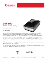
DW-100
Brand: Canon Pages: 5

DIM-787
Brand: Canon Pages: 98


