Panasonic RAMSA WR-S208, Operating Instructions Manual
The Panasonic RAMSA WR-S208 is a high-quality audio mixer designed for professional sound applications. With its advanced features and intuitive controls, this versatile device allows users to achieve exceptional sound quality. To ensure seamless operation, make sure to download the free Operating Instructions Manual from our website manualshive.com for detailed setup instructions and guidance.
Share
Download


Reviews:
No comments
Related manuals for RAMSA WR-S208

4742022040119
Brand: liebfeld Pages: 26

MM-4220 C
Brand: Marenius Pages: 11

BO100
Brand: Behringer Pages: 2

RED LLAMA Mk II WHE-203
Brand: Way Huge Pages: 2

SL-KE05
Brand: Kasanova Pages: 24

Mix5
Brand: Mackie Pages: 12

CRAZY8 BEATS
Brand: twisted electrons Pages: 16

HDMIDAC2
Brand: PhDsolutions Pages: 15

Loud'n Proud
Brand: Mad Professor Pages: 2

DM1295
Brand: Numark Pages: 12
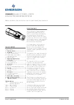
PENBERTHY CTE
Brand: Emerson Pages: 5

ST. LOUIS MINIMIX
Brand: Cimo Pages: 10

Plexi-Drive
Brand: Wampler Pages: 2

Tone-Lok TC7
Brand: Ibanez Pages: 2

DJM-400 - CDJ-400 Package
Brand: Pioneer Pages: 16

DJM-4000
Brand: Pioneer Pages: 28

DJM-250-K
Brand: Pioneer Pages: 44

DJM-400 - CDJ-400 Package
Brand: Pioneer Pages: 92


