Panasonic QUASAR PV-C1320, Service Manual
The Panasonic QUASAR PV-C1320 Operating Manual is a comprehensive guide that allows users to maximize the functionality of their device. This manual is available for download for free from manualshive.com, providing users easy access to the instructions they need to operate the product effectively.
Share
Download


Reviews:
No comments
Related manuals for QUASAR PV-C1320
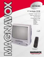
CC19B1MG
Brand: Magnavox Pages: 2

SL260D
Brand: Symphonic Pages: 8

DVK-47N
Brand: Daewoo Pages: 21

DV-K611
Brand: Daewoo Pages: 25

DPB-10000P
Brand: Daewoo Pages: 21

VRC602M
Brand: Magnavox Pages: 49

MVR430MG - Vcr Mono
Brand: Magnavox Pages: 47

13MDTD20 - Dvd-video Player
Brand: Magnavox Pages: 54

DV225MG9 - DVD Player And 4 Head Hi-Fi Stereo VCR
Brand: Magnavox Pages: 2

MSD805
Brand: Magnavox Pages: 28

MCMV1308
Brand: Magnasonic Pages: 68

MV-6010G
Brand: Teac Pages: 50

MV-8080G
Brand: Teac Pages: 61

SRTD219
Brand: Sylvania Pages: 44

VR694HF
Brand: RCA Pages: 88

DRC6200N
Brand: RCA Pages: 64

DX-9810
Brand: Daewoo Pages: 33

TFTV4980M
Brand: Palsonic Pages: 26


