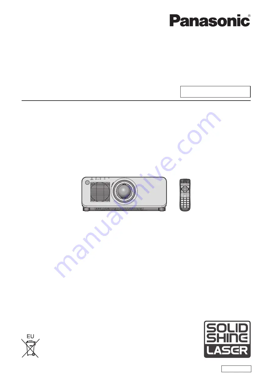
background image

Thank you for purchasing this Panasonic product.


This manual is common to all the models regardless of suffixes of the Model No.


z

for Taiwan

BT: Black model, the standard zoom lens supplied


z

for India

BD: Black model, the standard zoom lens supplied   

LBD: Black model, the lens sold separately

WD: White model, the standard zoom lens supplied   

LWD: White model, the lens sold separately


z

for Asia (except for Taiwan, India, Korea) / Oceania / Africa

BA/B: Black model, the standard zoom lens supplied   

LBA/LB: Black model, the lens sold separately

WA/W: White model, the standard zoom lens supplied   

LWA/LW: White model, the lens sold separately


z

for other countries or regions

B: Black model, the standard zoom lens supplied   

LB: Black model, the lens sold separately

W: White model, the standard zoom lens supplied   

LW: White model, the lens sold separately


Before operating this product, please read the instructions carefully and save this manual 

for future use.


Before using this product, be sure to read “Read this first!” (

x

 pages 5 to 16).

DPQP1064ZD

DLP™ Projector  

Commercial Use

Operating Instructions

Functional Manual

ENGLISH

Model No. 

PT-RZ770


PT-RW730


PT-RZ660


PT-RW620

Summary of Contents for PT-RZ660

Page 1: ...lens supplied LBA LB Black model the lens sold separately WA W White model the standard zoom lens supplied LWA LW White model the lens sold separately z z for other countries or regions B Black model...

Page 2: ...tion function shutter synchronization function 55 Chapter 3 Basic Operations Switching on off the projector 58 Connecting the power cord 58 Power indicator 58 Switching on the projector 59 When the in...

Page 3: ...19 PROJECTOR SETUP menu 120 PROJECTOR ID 120 PROJECTION METHOD 120 OPERATION SETTING 121 LIGHT OUTPUT 125 BRIGHTNESS CONTROL 126 STANDBY MODE 130 QUICK STARTUP 130 NO SIGNAL SHUT OFF 131 NO SIGNAL LIG...

Page 4: ...Light source temperature indicators 178 When an indicator lights up 178 Maintenance 180 Before maintaining the projector 180 Maintenance 180 Troubleshooting 181 SELF TEST indications 183 Chapter 7 App...

Page 5: ...ectrician Do not defeat the purpose of the earthing plug WARNING This equipment is compliant with Class A of CISPR32 In a residential environment this equipment may cause radio interference CAUTION To...

Page 6: ...viations pursuant to Laser Notice No 50 dated June 24 2007 IEC 60825 1 2007 LASER RADIATION AVOID DIRECT EYE EXPOSURE CLASS 3R LASER PRODUCT WAVE LENGTH 448 462nm MAXIMUM OUTPUT 248mW PULSE DURATION 1...

Page 7: ...r plug This plug will only fit a grounding type power outlet This is a safety feature If you are unable to insert the plug into the outlet contact an electrician Do not defeat the purpose of the groun...

Page 8: ...tested and found to comply with the limits for a Class A digital device pursuant to part 15 of the FCC Rules These limits are designed to provide reasonable protection against harmful interference whe...

Page 9: ...13 amp socket If a new plug is to be fitted please observe the wiring code as shown below If in any doubt please consult a qualified electrician WARNING THIS APPLIANCE MUST BE EARTHED IMPORTANT The wi...

Page 10: ...s risk group 3 is as follows Projection lens Model No Risk group ET DLE250 Risk group 3 1 ET DLE350 ET DLE450 1 When the projector is used with the optional Zoom Lens Model No ET DLE250 ET DLE350 ET D...

Page 11: ...2 PT RZ770 PT RW730 ET DLE250 1 1 0 34 0 21 0 41 0 31 ET DLE350 1 8 0 35 0 22 0 43 0 32 ET DLE450 2 8 0 37 0 24 0 45 0 34 PT RZ660 PT RW620 ET DLE250 1 1 0 34 0 21 0 41 0 31 ET DLE350 1 7 0 33 0 21 0...

Page 12: ...hich are damaged or wall outlets which are coming loose from the wall Do not handle the power plug and power connector with wet hands Failure to observe this will result in electric shocks Do not over...

Page 13: ...ould only be carried out by a qualified technician If installation is not carried out and secured correctly it can cause injury or accidents such as electric shocks f f Be sure to use the wire provide...

Page 14: ...ocations exposed to direct sunlight or near heaters Do not place your hands in the openings beside the optical lens while shifting the lens Failure to observe this could cause injury Do not install th...

Page 15: ...ENGLISH 15 Read this first To remove the battery Remote Control Battery 1 Press the guide and lift the cover ii i 2 Remove the batteries...

Page 16: ...do pela bateria pode irritar a garganta danificar o lacre do inv lucro ou o vazamento provocar calor ruptura da blindagem e produzir fogo devido ao curto circuito dos terminais N o incinere nem aque a...

Page 17: ...T Alliance f f Art NetTM Designed by and Copyright Artistic Licence Holdings Ltd f f Adobe Adobe Flash Player and Adobe Reader are trademarks or registered trademarks of Adobe Systems Inc in the Unite...

Page 18: ...ce and a lineup of various optional lenses Long life and high reliability The maintenance cost for long term operation is reduced by the unique light source cooling control technology and improvement...

Page 19: ...ENGLISH 19 Chapter 1 Preparation This chapter describes things you need to know or check before using the projector...

Page 20: ...ttach the Lens Mount Cover Not doing so may cause failure due to accumulating dust internally r rDo not set up the projector outdoors The projector is designed for indoor use only r rDo not set up the...

Page 21: ...ing the focus unstable in the period just after switching on the power It is recommended that images be projected continuously for at least 30 minutes before the focus is adjusted r rDo not install th...

Page 22: ...alling the projector with a method other than the floor installation using the adjustable feet top placed on the floor or the ceiling installation use the five screw holes for ceiling mount as shown i...

Page 23: ...ulge your password in case you receive such inquiries f f The connecting network must be secured by a firewall etc f f Set a password for the web control and restrict the users who can log in A passwo...

Page 24: ...een r rDo not touch the surface of the projection lens with your bare hands If the surface of the projection lens becomes dirty from fingerprints or anything else this will be magnified and projected...

Page 25: ...7 000 hours The luminance can be maintained as much as possible for the same runtime by setting the PROJECTOR SETUP menu OPERATION SETTING CONSTANT MODE to AUTO This time is rough estimate when the pr...

Page 26: ...KKL5244 1 Only models with lens CD ROM 1 1JK1RZ770BU AAA R03 or AAA LR03 battery 2 For remote control unit Attention f f After unpacking the projector discard the power cord cap and packaging material...

Page 27: ...ible with the Multi Monitoring Control Software can be downloaded from the Panasonic website https panasonic net cns prodisplays Optional accessories Optional accessories product name Model No Project...

Page 28: ...UNCTION button Assigns a frequently used operation as a shortcut button x page 74 9 Number 0 9 buttons Used for entering an ID number or a password in a multiple projector environment 10 AUTO SETUP bu...

Page 29: ...control can control at angles of up to 30 vertically and horizontally but the effective control range may be reduced f f If there are any obstacles between the remote control and the remote control si...

Page 30: ...tor TEMP Indicates the internal temperature status 6 Not used with this projector 7 Adjustable feet Adjusts the projection angle 8 Air intake port 9 Projection lens Only models with lens 10 Remote con...

Page 31: ...SDI button Switches the input to SDI Only for PT RZ770 PT RZ660 9 MENU button Displays or hides the main menu x page 77 Returns to the previous menu when a sub menu is displayed If you press the MENU...

Page 32: ...iant signal input to the SERIAL MULTI PROJECTOR SYNC IN terminal This terminal is also used to connect multiple projectors when balancing the contrast as a combined screen or synchronizing the effects...

Page 33: ...o ALL so you can use it as it is Set the ID numbers of the projector body and remote control as necessary For details on setting the ID number of the remote control refer to Setting ID number of the r...

Page 34: ...34 ENGLISH Chapter 2 Getting Started This chapter describes things you need to do before using the projector such as the setup and connections...

Page 35: ...Menu item Setting value Menu item Setting value FRONT REAR FRONT FRONT REAR REAR FLOOR CEILING AUTO or CEILING FLOOR CEILING AUTO or CEILING Portrait setting and projecting forward Portrait setting an...

Page 36: ...f f To ensure projector performance and security installation of the Ceiling Mount Bracket must be carried out by your dealer or a qualified technician Projected image and throw distance Install the p...

Page 37: ...tor top A2 Distance between the projector and the screen from the screen bottom edge to the projector bottom 1 The mirror reflection surface cannot be seen from the outside because it is located insid...

Page 38: ...ION f f Do not use the projector and the high powered laser equipment in the same room The DLP chips can be damaged if a laser beam hits the projection lens surface GEOMETRY projection range VERTICAL...

Page 39: ...ther Only CURVED CORRECTION used Vertical keystone correction angle Horizontal keystone correction angle Vertical keystone correction angle Horizontal keystone correction angle Min value of R2 L2 Min...

Page 40: ...te focus zoom lens Long focus zoom lens Ultra long focus zoom lens Projection lens Model No ET DLE250 ET DLE350 ET DLE450 Standard zoom lens ET DLE085 ET DLE150 ET DLE250 ET DLE350 ET DLE450 ET DLE055...

Page 41: ...rd zoom lens ET DLE085 ET DLE150 ET DLE250 ET DLE350 ET DLE450 ET DLE055 Fixed Throw ratio 1 2 3 3 6 1 3 6 5 4 1 5 4 8 6 1 Projected image size Projection distance L Diagonal SD Height SH Width SW Min...

Page 42: ...50 ET DLE450 Standard zoom lens ET DLE085 ET DLE150 ET DLE250 ET DLE350 ET DLE450 ET DLE055 Fixed Throw ratio 1 2 7 4 3 1 4 3 6 5 1 6 5 10 3 1 Projected image size Projection distance L Diagonal SD He...

Page 43: ...LE450 Standard zoom lens ET DLE085 ET DLE150 ET DLE250 ET DLE350 ET DLE450 ET DLE055 Fixed Throw ratio 1 2 4 3 8 1 3 8 5 7 1 5 6 9 0 1 Projected image size Projection distance L Diagonal SD Height SH...

Page 44: ...d zoom lens ET DLE085 ET DLE150 ET DLE250 ET DLE350 ET DLE450 ET DLE055 Fixed Throw ratio 1 2 4 3 8 1 3 8 5 7 1 5 6 9 0 1 Projected image size Projection distance L Diagonal SD Height SH Width SW Min...

Page 45: ...zoom lens ET DLE085 ET DLE150 ET DLE250 ET DLE350 ET DLE450 ET DLE055 Fixed Throw ratio 1 2 9 4 6 1 4 5 6 9 1 6 8 10 8 1 Projected image size Projection distance L Diagonal SD Height SH Width SW Min...

Page 46: ...5 x SD 0 0442 0 9 1 2 1 4 3 0 7772 x SD 0 0471 0 9621 x SD 0 0442 ET DLE150 1 3 1 9 1 16 10 1 1259 x SD 0 0540 1 6243 x SD 0 0498 1 3 1 9 1 16 9 1 1572 x SD 0 0540 1 6695 x SD 0 0498 1 6 2 3 1 4 3 1 2...

Page 47: ...SD 0 0800 3 2612 x SD 0 0792 2 4 3 8 1 16 9 2 1223 x SD 0 0800 3 3519 x SD 0 0792 2 9 4 6 1 4 3 2 3371 x SD 0 0800 3 6912 x SD 0 0792 ET DLE350 3 8 5 7 1 16 10 3 2550 x SD 0 1351 4 9185 x SD 0 1346 3...

Page 48: ...becomes rectangular The adjustable feet can also be used to adjust the projector to be level when it is tilted in the horizontal direction Adjustable feet can be extended by turning them as shown in t...

Page 49: ...ses which are not manufactured by Panasonic Always use the standard zoom lens supplied with the projector or the specified projection lens Note f f In case of the ultra short focus zoom lens Model No...

Page 50: ...over and align the projection lens guide to the guide groove of the projector and insert to the end Fig 1 2 Turn the projection lens clockwise until it clicks Fig 2 3 Attach the Lens Mount Cover Fig 3...

Page 51: ...base corrector TBC must be connected f f If synchronization signals output from computers or video equipment are disrupted due to changes in the video output setting or other reasons colors of projec...

Page 52: ...l is connected In such a case connect the time base corrector TBC between the projector and the external devices Note f f It may be necessary to switch the setting in the DISPLAY OPTION menu DVI D IN...

Page 53: ...ojector to a computer or an external device use the power cord supplied with each device and commercially available shielded cables Note f f Switching of the setting in the DISPLAY OPTION menu DVI D I...

Page 54: ...e with CAT5e or higher using tools such as a cable tester or cable analyzer When a relay connector is used include it in the measurement f f Do not use a hub between the twisted pair cable transmitter...

Page 55: ...zation function A linked screen with balanced contrast can be displayed by sharing the brightness level of the video signal being input to each projector To use this function set the PROJECTOR SETUP m...

Page 56: ...munication cable straight all connected Communication cable straight all connected Note f f The contrast synchronization function and the shutter synchronization function can be used simultaneously f...

Page 57: ...ENGLISH 57 Chapter 3 Basic Operations This chapter describes basic operations to start with...

Page 58: ...wer cord 1 Check the shapes of the AC IN terminal on the side of the projector and the power cord connector and insert the connector completely in the correct direction until you hear the side tabs cl...

Page 59: ...ximately five seconds after the projector is turned off the indicator does not light up even if the power is turned on Turn on the power again after the power indicator ON G STANDBY R lights blinks in...

Page 60: ...power was turned off at the previous use by pressing the OFF side of the MAIN POWER switch or by using the breaker directly while projecting the power indicator ON G STANDBY R lights up in green and...

Page 61: ...T OUTPUT LEVEL f f For the relationship between the luminance and the runtime refer to Interrelation of luminance and runtime x page 63 f f For details on each setting item refer to the PROJECTOR SETU...

Page 62: ...forms correction by the brightness sensor on one projector without synchronizing with the other projectors The duration that the constant brightness is kept will become longer by setting the value of...

Page 63: ...0 0 34 0 2 400 100 0 37 0 2 600 40 000 100 0 33 0 2 300 f f To set the projector based on luminance Luminance lm When CONSTANT MODE is set to OFF When CONSTANT MODE is set to AUTO or PC MAX LIGHT OUTP...

Page 64: ...ght source conditions of use installation environment etc f f The duration of use is referred to as the runtime when you use the projector successively The duration of use is an estimated duration and...

Page 65: ...CHANGE STANDBY MODE NORMAL ENTER 2 Press the ENTER button to proceed to the initial setting Note f f The preceding initial setting screen is displayed when the projector is switched on for the first...

Page 66: ...ojector After completed the initial setting you can change the setting from the PROJECTOR SETUP menu DATE AND TIME The current settings are displayed in LOCAL DATE and LOCAL TIME 1 Press qw to switch...

Page 67: ...ntinuously for at least 30 minutes before the focus is adjusted 6 1 8 5 3 7 9 3 2 4 1 5 7 8 9 2 6 1 Press the FOCUS button to roughly adjust the focus of the projected image x page 70 2 Change the set...

Page 68: ...lights in orange The fan keeps running 3 Wait for a few seconds until the power indicator ON G STANDBY R of the projector body lights blinks in red 4 Press the OFF side of the MAIN POWER switch to tur...

Page 69: ...d DIGITAL LINK Switches the input to DIGITAL LINK The image of the signal input to the DIGITAL LINK LAN terminal is projected DVI D Switches the input to DVI D The image of the signal input to the DVI...

Page 70: ...is recommended that images be projected continuously for at least 30 minutes before the focus is adjusted f f Only FOCUS is displayed in yellow so that the displayed menu item can be recognized by co...

Page 71: ...n NORMAL Moves the lens to the home position Select this item when replacing or removing the projection lens Select this item when the Fixed focus Lens Model No ET DLE055 is used for projection DLE030...

Page 72: ...mage height V Projected image width H 0 5 V 0 16 V 0 1 H 0 3 H 0 1 H Standard projection position Projected image height V Projected image width H 0 5 V 0 16 V 0 1 H 0 28 H PT RW730 PT RW620 Standard...

Page 73: ...closed f f The fade in fade out time of the image can be set by the DISPLAY OPTION menu SHUTTER SETTING f f The light source may be lit dimly due to warm up when the shutter function is used in the op...

Page 74: ...ding on the computer model f f Automatic adjustment may not be possible for the synchronization signal for composite sync or SYNC ON GREEN f f Image may be disrupted for a few seconds during automatic...

Page 75: ...keep pressing the ID SET button on the remote control for at least three seconds to set the ID number of the remote control to ALL In addition when the ID number of the projector is unknown setting t...

Page 76: ...76 ENGLISH Chapter 4 Settings This chapter describes the settings and adjustments you can make using the on screen menu...

Page 77: ...LAY LANGUAGE DISPLAY OPTION PROJECTOR SETUP TEST PATTERN SIGNAL LIST SECURITY NETWORK MENU SELECT SUB MENU P IN P ENTER 2 Press as to select an item from the main menu f f The selected item is highlig...

Page 78: ...menu ON SCREEN DISPLAY OSD DESIGN The selected item is displayed with the yellow cursor by the factory default f f In the portrait setting the on screen menu is displayed sideways To display the on sc...

Page 79: ...S 0 82 COLOR 0 2 83 TINT 0 83 COLOR TEMPERATURE DEFAULT 2 83 WHITE GAIN 10 85 GAMMA DEFAULT 85 SYSTEM DAYLIGHT VIEW OFF 2 86 SHARPNESS 6 2 86 NOISE REDUCTION OFF 2 87 DYNAMIC CONTRAST 2 2 87 SYSTEM SE...

Page 80: ...N 108 DIGITAL LINK IN 109 SDI IN 1 110 ON SCREEN DISPLAY 111 CLOSED CAPTION SETTING 113 IMAGE ROTATION OFF 114 BACK COLOR BLUE 114 STARTUP LOGO DEFAULT LOGO 114 UNIFORMITY 115 SHUTTER SETTING 116 FREE...

Page 81: ...G OFF 148 TEXT CHANGE 149 CONTROL DEVICE SETUP 149 CONTROL DEVICE PASSWORD CHANGE 150 NETWORK Sub menu item Factory default Page DIGITAL LINK MODE AUTO 152 DIGITAL LINK STATUS 152 NETWORK SETUP 153 NE...

Page 82: ...for still image input signals and STANDARD for movie based input signals f f Rec 709 is an abbreviation of ITU R Recommendation BT 709 and is a color standard of high vision broadcasting f f DICOM is...

Page 83: ...eenish color 31 31 Press q Adjusts skin tone toward reddish purple COLOR TEMPERATURE You can switch the color temperature if the white areas of the projected image are bluish or reddish Adjusting with...

Page 84: ...URE correctly All colors will not be displayed properly unless adequate adjustment is made If the adjustment does not look suitable you can press the DEFAULT button on the remote control to return the...

Page 85: ...displayed 7 Press asqw to select the text and press the ENTER button to enter the text 8 Press asqw to select OK and press the ENTER button f f The name set to color temperature is changed Note f f T...

Page 86: ...d SYSTEM DAYLIGHT VIEW You can correct the image to the optimal vividness even if it is projected under a bright light 1 Press as to select SYSTEM DAYLIGHT VIEW 2 Press qw or the ENTER button f f The...

Page 87: ...justment screen is displayed 3 Press qw to switch the item f f The items will switch each time you press the button OFF Disables the dynamic contrast function 1 Adjusts the light source and compensate...

Page 88: ...ight source has turned off by this function g g When the brightness level of the video signal being input has exceeded the value set in LIGHTS OUT SIGNAL LEVEL g g When the input signal is gone g g Wh...

Page 89: ...5p RGB 1080 30p RGB 1080 50i RGB 1080 60i RGB 2K 24p RGB 2K 25p RGB 2K 30p RGB 2K 48p YPBPR 2K 50p YPBPR or 2K 60p YPBPR 4 Press the ENTER button Note f f For details of the types of video signals tha...

Page 90: ...The image position moves up Press s The image position moves down Horizontal right and left adjustment Press w The image position moves to the right Press q The image position moves to the left Note f...

Page 91: ...ls with an aspect ratio of 4 3 or 5 4 4 Wide screen signals are input signals with an aspect ratio of 16 10 16 9 15 9 or 15 10 Note f f Some size modes are not available for certain types of input sig...

Page 92: ...ent screen is displayed 3 Press qw to adjust f f Adjustment value will change between 0 and 31 Adjust the image so that the amount of interference is at a minimum Note f f Adjustment may not be possib...

Page 93: ...n f f The GEOMETRY KEYSTONE or GEOMETRY CURVED CORRECTION screen is displayed 4 Press as to select the item to adjust 5 Press qw to adjust KEYSTONE LENS THROW RATIO Set the throw ratio Select the valu...

Page 94: ...ge blending adjustment may not be performed correctly depending on the environment when using the ADVANCED MENU menu EDGE BLENDING and GEOMETRY simultaneously f f The optional Upgrade Kit Model No ET...

Page 95: ...olution will degrade f f When the ADVANCED MENU menu FRAME RESPONSE is set to FAST DIGITAL CINEMA REALITY cannot be set BLANKING You can adjust the blanking width if there are noises at the edge of th...

Page 96: ...f f Image may be disrupted during automatic adjustment but this is not a malfunction f f INPUT RESOLUTION can be adjusted only when an RGB signal is input to the RGB 1 IN terminal or the RGB 2 IN ter...

Page 97: ...orrection width for the projectors to be joined with the same value Optimal joining is not possible with projectors that have different correction widths The optimal point is the point at which these...

Page 98: ...adjustment makes only the border area darker f f The joining part may look discontinuous depending on the position you are looking from when a screen with high gain or rear screen is used f f When str...

Page 99: ...set f f FRAME RESPONSE cannot be set while in the P IN P mode RASTER POSITION This will allow the position of the image to move within the display area arbitrarily when the input image is not using t...

Page 100: ...screen display 1 Press as to select the display language and press the ENTER button ENTER DISPLAY LANGUAGE SELECT SET f f Various menus settings adjustment screens control button names etc are display...

Page 101: ...g AUTO TESTPATTERN to ON the test pattern for the selected color is displayed 6 Press as to select RED GREEN or BLUE f f Only GAIN can be adjusted when WHITE is selected for 3COLORS 7 Press qw to adju...

Page 102: ...EDGE BLENDING ON USER AUTO TESTPATTERN f f When using a colorimeter or similar instrument to take measurement measure the colors displayed in AUTO TESTPATTERN f f A difference in the color coordinates...

Page 103: ...UTO SETUP Set this when adjusting a special signal or horizontally long such as 16 9 signal Setting with MODE 1 Press as to select AUTO SETUP 2 Press the ENTER button f f The AUTO SETUP screen is disp...

Page 104: ...ING Set the backup function that switches the signal to the backup input signal as seamless as possible when input signal is disrupted 1 Press as to select BACKUP INPUT SETTING 2 Press the ENTER butto...

Page 105: ...s possible f f When AUTOMATIC SWITCHING is set to ENABLE and BACKUP INPUT STATUS is ACTIVE the signal is switched to the backup input if a disruption occurs in the input signal f f When AUTOMATIC SWIT...

Page 106: ...RESOLUTION g g 1920x1080p 1920x1080i 10 Press the ENTER button f f The confirmation screen is displayed 11 Press qw to select OK and press the ENTER button Note f f Settings in RESOLUTION and VERTICAL...

Page 107: ...a resolution that supports plug and play Setting EDID MODE in DVI D IN 1 Press as to select DVI D IN 2 Press the ENTER button f f The DVI D IN screen is displayed 3 Press as to select EDID MODE 4 Pre...

Page 108: ...HDMI terminal of an external device such as a Blu ray disc player is input to the HDMI IN terminal 0 1023 Select this item when the signal output from the DVI D terminal of an external device such as...

Page 109: ...e depending on the computer or video device in use DIGITAL LINK IN Set this item in accordance with the video signal input to the DIGITAL LINK LAN terminal Setting SIGNAL LEVEL in DIGITAL LINK IN 1 Pr...

Page 110: ...TION g g 1920x1080p 1920x1080i 10 Press the ENTER button f f The confirmation screen is displayed 11 Press qw to select OK and press the ENTER button Note f f Settings in RESOLUTION and VERTICAL SCAN...

Page 111: ...u screen OSD 1 Press as to select ON SCREEN DISPLAY 2 Press the ENTER button f f The ON SCREEN DISPLAY screen is displayed 3 Press as to select OSD POSITION 4 Press qw to switch the item f f The items...

Page 112: ...ursor 1 Press as to select ON SCREEN DISPLAY 2 Press the ENTER button f f The ON SCREEN DISPLAY screen is displayed 3 Press as to select OSD MEMORY 4 Press qw to switch the item f f The items will swi...

Page 113: ...source is turned off after the no signal lights out function is executed CLOSED CAPTION SETTING only when NTSC or 480 60i YCBCR signal is input Set closed captions Selecting the closed caption displa...

Page 114: ...n screen display direction does not change even when this item is set to anything other than OFF Set the DISPLAY OPTION menu ON SCREEN DISPLAY OSD ROTATION as required f f The GEOMETRY setting becomes...

Page 115: ...dark HORIZONTAL Press w The left side color becomes pale or the right side color becomes dark Press q The right side color becomes pale or the left side color becomes dark Setting PC CORRECTION Only...

Page 116: ...e item OPEN The projector goes into projection mode with the shutter function disabled shutter opened when the power is turned on CLOSE The projector goes into projection mode with the shutter functio...

Page 117: ...he PROJECTOR SETUP menu MULTI PROJECTOR SYNC For details on contrast synchronization function refer to the PROJECTOR SETUP menu MULTI PROJECTOR SYNC x page 135 f f The shutter synchronization function...

Page 118: ...n on screen display is hidden off Adjusting the waveform Project the luminance adjustment signal of a commercial test disk 0 0 IRE or 7 5 IRE 100 100 IRE and adjust Signal level Image displayable area...

Page 119: ...LINK IN SDI IN SIGNAL LEVEL SDI IN is supported only for PT RZ770 PT RZ660 CUT OFF Each red green and blue color component can be removed 1 Press as to select CUT OFF 2 Press the ENTER button f f The...

Page 120: ...om the projectors with other ID numbers f f Refer to Setting ID number of the remote control x page 75 for how to set the ID number on the remote control PROJECTION METHOD Set the projection method in...

Page 121: ...inance will decrease compared to LONG LIFE1 but set this item to increase the expected life of the light source The estimated runtime is approximately 61 000 hours LONG LIFE3 1 The luminance will decr...

Page 122: ...runtime becomes longer 5 Press as to select APPLY 6 Press the ENTER button 7 When the confirmation screen is displayed press qw to select OK and press the ENTER button Note f f LIGHT OUTPUT can be ad...

Page 123: ...0 2 000 f f To set the projector based on luminance Luminance lm When CONSTANT MODE is set to OFF When CONSTANT MODE is set to AUTO or PC MAX LIGHT OUTPUT LEVEL LIGHT OUTPUT Runtime hour MAX LIGHT OUT...

Page 124: ...in synchronization Up to four groups A to D can be set within the same subnet by using the network function Up to eight projectors can be registered and synchronized in one group 7 Press as to select...

Page 125: ...ONSTANT MODE in BRIGHTNESS CONTROL SETUP set to AUTO and LINK set to OFF the brightness will be corrected until it reaches the value set in MAX LIGHT OUTPUT LEVEL f f The variation in brightness may i...

Page 126: ...not correct the brightness of the screen by the brightness sensor AUTO Corrects the brightness of the screen by the brightness sensor When the brightness of light source or white balance changes the b...

Page 127: ...r of the light source do not stabilize for approximately eight minutes after the light source is turned on Therefore the brightness and color of the light source will be automatically measured after a...

Page 128: ...set to AUTO and LINK is set to GROUP A through GROUP D The screen shows the status of the brightness control of synchronized projectors up to eight units including the projector being controlled throu...

Page 129: ...r 1 Multi Monitoring Control Software is included in the supplied CD ROM Note f f If the synchronized projectors are not displayed in the list check the following g g Are there devices with the same I...

Page 130: ...PROJECTOR SYNC OUT terminal can be used during standby f f When ECO is set it may take approximately 10 seconds longer before the projector starts projecting after the power is turned on compared wit...

Page 131: ...l switch each time you press the button DISABLE Disables the no signal lights out function 10SEC 5MIN Turns off the light source when there is no input signal for the preset period Select 10SEC 20SEC...

Page 132: ...will start with the DVI D input even if STARTUP INPUT SELECT is set to LAST USED DATE AND TIME Set the time zone date and time of the built in clock of the projector Setting the time zone 1 Press as t...

Page 133: ...press the button OFF Disables the schedule function ON Enables the schedule function Refer to How to assign a program x page 133 or How to set a program x page 133 for how to set the schedule Note f f...

Page 134: ...ven lower than that of LONG LIFE1 LONG LIFE3 Controls the power to increase the life of the light source to the maximum although the luminance is even lower than that of LONG LIFE2 USER1 Controls the...

Page 135: ...lect MULTI PROJECTOR SYNC 2 Press the ENTER button f f The MULTI PROJECTOR SYNC screen is displayed 3 Press as to select MODE 4 Press qw to switch the item f f The items will switch each time you pres...

Page 136: ...s are not correctly connected or not correctly set Check the cable connection status and the projector setting for each projector that is linked 5 Press as to select SHUTTER SYNC 6 Press qw to switch...

Page 137: ...speed 19200 38400 7 Press as to select IN PARITY 8 Press qw to switch the item f f The items will switch each time you press the button NONE Select the parity condition EVEN ODD Setting the communica...

Page 138: ...T is set to DIGITAL LINK communication speed for input is fixed to 9 600 bps and the parity is fixed to NONE REMOTE2 MODE Set the REMOTE 2 IN terminal 1 Press as to select REMOTE2 MODE 2 Press qw to s...

Page 139: ...lay the status of the projector 1 Press as to select STATUS 2 Press the ENTER button f f The STATUS screen is displayed 3 Press qw to switch the pages f f The page will change each time you press the...

Page 140: ...STATUS screen is displayed f f Some items in SIGNAL INFORMATION may be displayed and others not displayed depending on the signal being input f f If any abnormality has occurred on the projector pres...

Page 141: ...signal To delete only a part of a registered signal perform the procedure described in Deleting the registered signal x page 145 NETWORK E MAIL Returns the setting of the NETWORK menu NETWORK SETUP a...

Page 142: ...s as to select MAIN WINDOW or SUB WINDOW and press the ENTER button 5 Press as to select the input terminal to be displayed in the window and press the ENTER button 6 Press as to select an item SIZE S...

Page 143: ...K and other inputs cannot be displayed in P IN P f f The main window setting values are applied as image adjustment values such as the PICTURE menu PICTURE MODE GAMMA COLOR TEMPERATURE f f While in th...

Page 144: ...on Menu screen Color bar vertical Menu screen Color bar horizontal Menu screen 16 9 4 3 aspect frame Menu screen Focus Menu screen Input screen Displays the menu screen and input signal Internal test...

Page 145: ...stered signal Registered signals can be renamed 1 Press asqw to select the signal of which name is to be changed 2 Press the ENTER button f f The REGISTERED SIGNAL STATUS screen is displayed f f The m...

Page 146: ...GNAL SETUP screen is displayed 4 Press as to select LOCK IN RANGE 5 Press qw to switch the item f f The items will switch each time you press the button NARROW Select this item usually WIDE Widens the...

Page 147: ...ed f f The FUNCTION button on the remote control can be used instead of qw when SUB MEMORY is selected from the PROJECTOR SETUP menu FUNCTION BUTTON 2 Press asqw to select the sub memory number to reg...

Page 148: ...OM SHIFT 1 Press as to select SECURITY PASSWORD 2 Press qw to switch the item f f The items will switch each time you press the button OFF Disables the security password entry ON Enables the security...

Page 149: ...NTER button f f The CONTROL DEVICE SETUP screen is displayed 3 Press as to select CONTROL PANEL or REMOTE CONTROL CONTROL PANEL Sets the limitation on the control from the control panel REMOTE CONTROL...

Page 150: ...xes to RGB1 RGB2 Fixes to RGB2 DISABLE Disables button operations f f When INPUT SELECT BUTTON is selected in Step 7 once the switching of the item is completed press the MENU button to return to the...

Page 151: ...select OK and press the ENTER button f f To cancel select CANCEL Attention f f The initial password is AAAA as the factory default or when the PROJECTOR SETUP menu INITIALIZE ALL USER DATA is execute...

Page 152: ...s case the signal that the projector can receive is only up to 1080 60p 1 920 x 1 080 dots dot clock frequency 148 5 MHz f f If the communication method of the twist pair cable transmitter is set to l...

Page 153: ...ot be selected when the NETWORK menu Art Net SETUP is set to ON 2 X X X or ON 10 X X X NETWORK CONTROL Set up the control method of the network 1 Press as to select NETWORK CONTROL 2 Press the ENTER b...

Page 154: ...er The projector does not have the RETURN button but the same operation is available with the MENU button Art Net SETUP Make settings to use the Art Net function 1 Press as to select Art Net SETUP 2 P...

Page 155: ...izontal direction LENS V SHIFT Adjusts the lens shift in the vertical direction LENS FOCUS Adjusts the focus LENS ZOOM Adjusts the zoom POWER Controls the power status SHUTTER Controls the shutter FAD...

Page 156: ...156 ENGLISH Chapter 5 Operations This chapter describes how to use each function...

Page 157: ...y of the projector can be performed from a computer using the PJLink protocol Refer to PJLink protocol x page 186 for details f f Art Net Setting of the projector can be operated by the DMX controller...

Page 158: ...rojector f f Do not pull cables forcefully Also do not bend or fold cables unnecessarily f f To reduce the effects of noise as much as possible stretch out the cables between the twisted pair cable tr...

Page 159: ...on the power of the computer 2 Perform the network setting following the instruction of your network administrator f f Operation from the computer is possible by configuring the network setting of th...

Page 160: ...nd controls devices on multiple systems connected to a network using a computer f f For details of the Crestron ConnectedTM visit the website of Crestron Electronics Inc English only URL http www cres...

Page 161: ...it is not a malfunction f f Screenshot of a computer The size or the display of the screen may be different from this manual depending on the OS or the Web browser or the type of computer in use Righ...

Page 162: ...the status of the shutter function CLOSE Enabled closed OPEN Disabled open 5 OPERATING MODE Displays the setting status of OPERATING MODE 6 MAX LIGHT OUTPUT LEVEL Displays the setting status of MAX L...

Page 163: ...is high such as near a heating appliance Or the air exhaust port may be blocked LIGHT1 TEMPERATURE The temperature of the light source is high The projector may be used in an environment where the te...

Page 164: ...E The temperature around the optics module inside the projector is high The projector may be used in an environment where the temperature is high such as near a heating appliance EXHAUST AIR TEMPERATU...

Page 165: ...error log page Click Status Mail error log E mail error log is displayed if periodic E mail sending has failed Note f f Access error log and Mail error log display the recent few thousand accesses req...

Page 166: ...SDI input is supported only for PT RZ770 PT RZ660 Detail control page Click Projector control Detail control 4 3 5 2 1 8 9 7 6 10 1 Control of the projector The projector is controlled by clicking th...

Page 167: ...Enter the default gateway address when not using a DHCP server 6 DNS1 Enter the DNS1 server address Permissible characters for the entry of DNS1 server address primary Numbers 0 9 period Example 192 1...

Page 168: ...to be set up 5 Date Enter the date to be changed 6 Time Enter the time to be changed 7 Submit Updates the date and time settings Note f f The replacement of the battery inside the projector is requir...

Page 169: ...e is 60 minutes In this case another E mail will not be sent for 60 minutes after sending the temperature warning E mail even if it reaches the warning temperature 6 INTAKE AIR TEMPERATURE Change the...

Page 170: ...Internet service provider 2 SMTP Auth Set when the SMTP authentication is selected 3 POP server name Enter the POP server name Allowed characters Alphanumerics A Z a z 0 9 Minus sign and period 4 Use...

Page 171: ...UST AIR TEMPERATURE OK LIGHT1 TEMPERATURE OK LIGHT2 TEMPERATURE OK LIGHT1 STATUS OK LIGHT2 STATUS OK INTAKE AIR TEMP SENSOR OK OPTICS MODULE TEMP SENSOR OK EXHAUST AIR TEMP SENSOR OK LIGHT1 TEMP SENSO...

Page 172: ...R OK BRIGHTNESS SENSOR FAILED ANGLE SENSOR OK ATM SENSOR OK PHOSPHOR WHEEL1 OK PHOSPHOR WHEEL2 OK AC VOLTAGE OK Error code 00 00 00 00 00 00 00 00 00 00 00 00 80 00 00 00 Intake air temperature 25 deg...

Page 173: ...setting of the password Administrator account 1 3 2 4 1 Account Displays the account to change 2 Current User name Enter the user name before the change Password Enter the current password 3 New User...

Page 174: ...r the desired new password again 4 OK Determines the change of password Note f f To change the account of the Administrator entry of User name and Password in Current is required Crestron Connected TM...

Page 175: ...to freeze image quality 7 Back Returns to the previous page Tools page Click Tools in the operation page 1 2 3 4 5 1 Control System Set the information required for communicating with the controller...

Page 176: ...2 Hours Displays the runtime of the light source 1 and the light source 2 4 Power Status Displays the status of the power 5 Source Displays the selected input 6 Error Status Displays the error status...

Page 177: ...ENGLISH 177 Chapter 6 Maintenance This chapter describes inspection methods when there are problems and maintenance methods...

Page 178: ...8 and turn on the power again Blinking in red 1 time The light source is turned off since the projection lens cannot be detected f f Turn off the power and mount the projection lens again x page 49 f...

Page 179: ...f Wait at least five minutes in the current status f f Use the projector in an appropriate operating environment temperature 1 f f Remove any objects that are blocking the air intake exhaust port f f...

Page 180: ...Doing so may deteriorate the outer case f f When using chemically treated dust cloths follow the instructions written on its packaging Lens front surface Wipe off dirt and dust from the front surface...

Page 181: ...leted f f Is the polarity of the batteries set correctly 33 f f Are there any obstructions between the remote control and the remote control signal receiver of the projector 28 f f Is the remote contr...

Page 182: ...nsmitter and an external device and between the twisted pair cable transmitter and projector correctly done f f Is Art Net SETUP set to other than OFF 154 f f Are NET SUB NET UNIVERSE and START ADDRES...

Page 183: ...clock 4 H11 Intake air temperature sensor error 5 H12 Optical module temperature sensor error 5 H13 Exhaust air temperature sensor error 5 H14 Light source 1 temperature sensor error 5 H15 Light sourc...

Page 184: ...ure 1 The operating environment temperature is too high Use the projector in an appropriate operating environment temperature 1 2 The operating environment temperature is too low Use the projector in...

Page 185: ...ENGLISH 185 Chapter 7 Appendix This chapter describes specifications and after sales service for the projector...

Page 186: ...tter function enabled shutter closed ERST Error status query xxxxxx 1st byte Indicates fan errors and returns 0 2 f f 0 No error is detected f f 1 Warning f f 2 Error 2nd byte Indicates light source e...

Page 187: ...be switched using the NETWORK menu Art Net CHANNEL SETTING x page 155 The control details assigned to each channel are listed in the following table f f Channel assignment for USER is in factory defau...

Page 188: ...K 40 47 SDI Only for PT RZ770 PT RZ660 48 55 No operation 56 119 P IN P OFF 120 127 P IN P execution USER1 128 135 P IN P execution USER2 136 143 P IN P execution USER3 144 151 No operation 152 255 r...

Page 189: ...1 Operate together with LENS FUNCTION SELECT Performance Parameter Default value Lens adjustment High speed 0 31 100 Low speed 32 63 Fine adjustment 64 95 Operation stop 96 127 Lens adjustment Fine ad...

Page 190: ...e Parameter Default value OFF 0 31 255 PC 1 32 63 PC 2 64 95 PC 3 96 127 No operation 128 255 r r FREEZE Performance Parameter Default value No operation 0 31 128 OFF 32 95 No operation 96 159 ON 160...

Page 191: ...nd port number Initial set value 1024 of the projector and request a connection to the projector f f You can obtain both the IP address and the port number from the menu screen of the projector IP add...

Page 192: ...response String Details Termination symbol Message ERR1 Undefined control command CR 0x0d ERR2 Out of parameter range ERR3 Busy state or no acceptable period ERR4 Timeout or no acceptable period ERR5...

Page 193: ...acquisition command 00QPW CR r r Received data Header Data section Termination symbol Command example 0 0x30 0 0x30 Control command ASCII string CR 0x0d Data length 1 byte 1 byte Undefined length 1 b...

Page 194: ...on refer to Connecting example when using the contrast synchronization function shutter synchronization function x page 55 Connection for RS 232C communication Single projector Projector connecting te...

Page 195: ...or contrast synchronization function for shutter synchronization function 5 GND Earth 6 NC 7 RTS Connected internally 8 CTS 9 NC RS 232C communication conditions factory default Signal level RS 232C c...

Page 196: ...ng cases g g It matches the projector ID g g ID is designated as ALL and RESPONSE ID ALL is set to ON g g ID is designated as GROUP and RESPONSE ID GROUP is set to ON f f STX and ETX are character cod...

Page 197: ...onization function Control command The following table lists the commands that can be used to control the projector using a computer r r Projector control command Command Details Parameter response st...

Page 198: ...D 2 POWER OFF ON 3 RGB1 Other RGB1 4 RGB2 Other RGB2 5 DIGITAL LINK Other DIGITAL LINK 6 HDMI Other HDMI 7 DVI D Other DVI D 8 SHUTTER OFF ON 9 RST SET Controlled by remote control Controlled by exter...

Page 199: ...RGB 2 Moving image 3 RGB 2 Moving image 3 RGB 2 Moving image 3 RGB1 RGB l l l l l Moving image 1 l a l a a Y C input l a l a a VIDEO input l a l a a RGB2 RGB l l l l l Moving image 1 l a l a a DVI D R...

Page 200: ...Adjustment range of HORIZONTAL KEYSTONE Maximum of 15 1 Maximum of 40 1 Adjustment range of CURVED CORRECTION Vertical arc Maximum 50 1 Horizontal arc Maximum 50 1 Vertical arc Maximum 100 1 Horizont...

Page 201: ...0 74 3 R Y D H l l l 1080 50i 1 920 x 1 080i 28 1 50 0 74 3 R Y D H l l l 1080 24p 1 920 x 1 080 27 0 24 0 74 3 R Y D H l l l 1080 24sF 1 920 x 1 080i 27 0 48 0 74 3 R Y D H 1080 25p 1 920 x 1 080 28...

Page 202: ...R D H 1366 x 768 50 1 366 x 768 39 6 49 9 69 0 R D H 1366 x 768 60 1 366 x 768 47 7 59 8 85 5 R D H 1400 x 1050 50 1 400 x 1 050 54 1 50 0 99 9 R D H 1400 x 1050 60 1 400 x 1 050 64 0 60 0 108 0 R D H...

Page 203: ...Level B RGB 4 4 4 12bit 1080 24p 1 920 x 1 080 27 0 24 0 1 74 3 HD SDI YPBPR 4 2 2 10bit 1 920 x 1 080 27 0 24 0 1 74 3 3G SDI Level A RGB 4 4 4 10bit 1 920 x 1 080 27 0 24 0 1 74 3 3G SDI Level B RGB...

Page 204: ...RGB 4 4 4 10bit 2 048 x 1 080 33 8 30 0 1 74 3 3G SDI Level B RGB 4 4 4 10bit 2 048 x 1 080 33 8 30 0 1 74 3 3G SDI Level A RGB 4 4 4 12bit 2 048 x 1 080 33 8 30 0 1 74 3 3G SDI Level B RGB 4 4 4 12b...

Page 205: ...0B PT RZ660W PT RZ660LB PT RZ660LW PT RZ660BD PT RZ660WD PT RZ660LBD PT RZ660LWD PT RZ660BA PT RZ660WA PT RZ660LBA PT RZ660LWA PT RW620B PT RW620W PT RW620LB PT RW620LW PT RW620BD PT RW620WD PT RW620L...

Page 206: ...60825 1 2007 Other countries or regions Class 1 IEC EN 60825 1 2014 Risk Group Standard zoom lens ET DLE030 ET DLE055 ET DLE085 ET DLE150 Risk Group 2 IEC 62471 5 2015 ET DLE250 ET DLE350 ET DLE450 R...

Page 207: ...nchronization signal PBPR 0 7 V p p 75 DVI D IN terminal 1 set DVI D 24 p single link DVI 1 0 compliant HDCP compatible HDMI IN terminal 1 set HDMI 19 p HDCP compatible Deep Color compatible SDI IN te...

Page 208: ...lock frequency 148 5 MHz or less f f The HD SYNC and VD terminals do not support 3 value SYNC DVI D input f f Moving image signal resolution 480i 1 576i 1 to 1 920 x 1 080 Still image signal resolutio...

Page 209: ...s Unit mm 221 8 11 16 249 9 13 16 498 19 19 32 457 18 442 17 13 32 20 5 13 16 115 5 4 9 16 200 7 7 8 43 1 11 16 538 21 3 16 The above dimensions are obtained when the standard zoom lens is attached Ac...

Page 210: ...rop prevention set Service Model No TTRA0214 is necessary consult your dealer f f Ask a qualified technician to do the installation work such as mounting the projector on the ceiling f f Panasonic tak...

Page 211: ...K CONTROL 153 NETWORK SETUP 153 NETWORK STATUS 154 NOISE REDUCTION 87 NO SIGNAL LIGHTS OUT 131 NO SIGNAL SHUT OFF 131 O ON SCREEN button Remote control 28 73 ON SCREEN DISPLAY 111 On screen menu 77 OP...

Page 212: ...Index 212 ENGLISH ZOOM button Remote control 28 70...

Page 213: ...in the European Union If you wish to discard these items please contact your local authorities or dealer and ask for the correct method of disposal Product Information for Turkey only AEEE Y netmeli i...

Reviews: