Thank you for purchasing this Panasonic product.
■
This manual provides operating instructions for the PT-DZ16KU / PT-DZ16KE / PT-DZ16KD.
z
PT-DZ16KU: for North/Middle/South America and Taiwan
z
PT-DZ16KD: for India
z
PT-DZ16KE: for other countries or regions
■
Before operating this product, please read the instructions carefully and save this manual
for future use.
■
Before using this product, be sure to read “Read this first!” (
x
pages 2 to 11).
TQBJ0678
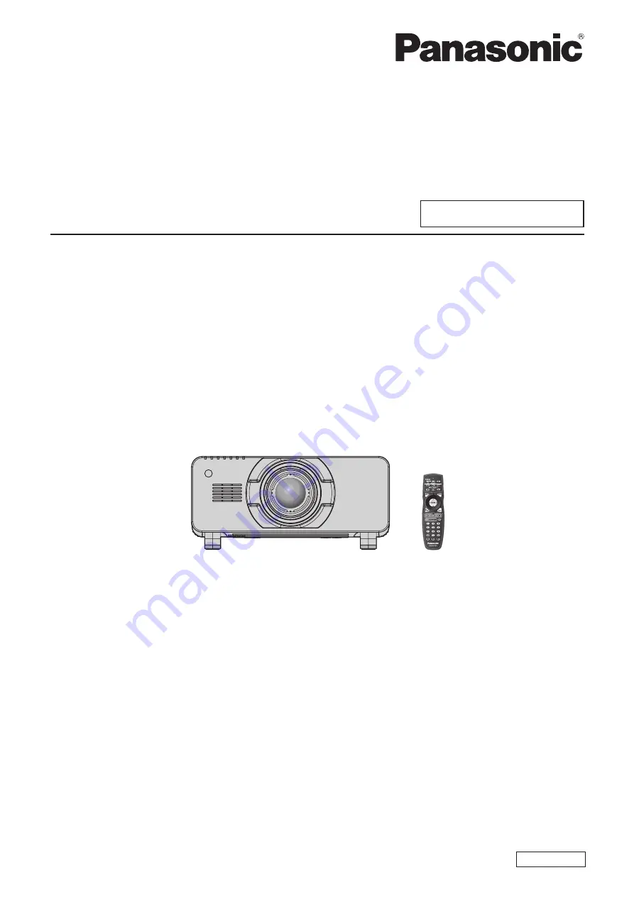
DLP™ Projector
Commercial Use
Operating Instructions
Functional Manual
ENGLISH
Model No.
PT-DZ16KU
PT-DZ16KE
PT-DZ16KD
The projection lens is sold separately.