background image

PROJECTOR

POWER

SYSTEM

SELECTOR

STD

RGB

INPUT1

INPUT2

INPUT3

BRIGHT

CONTRAST

LENS

+

PC-

MUTE

ON

SCREEN

NEXT

ID SELECT

ID ALL

1

2

3

4

5

6

7

8

9

0

MENU

ENTER

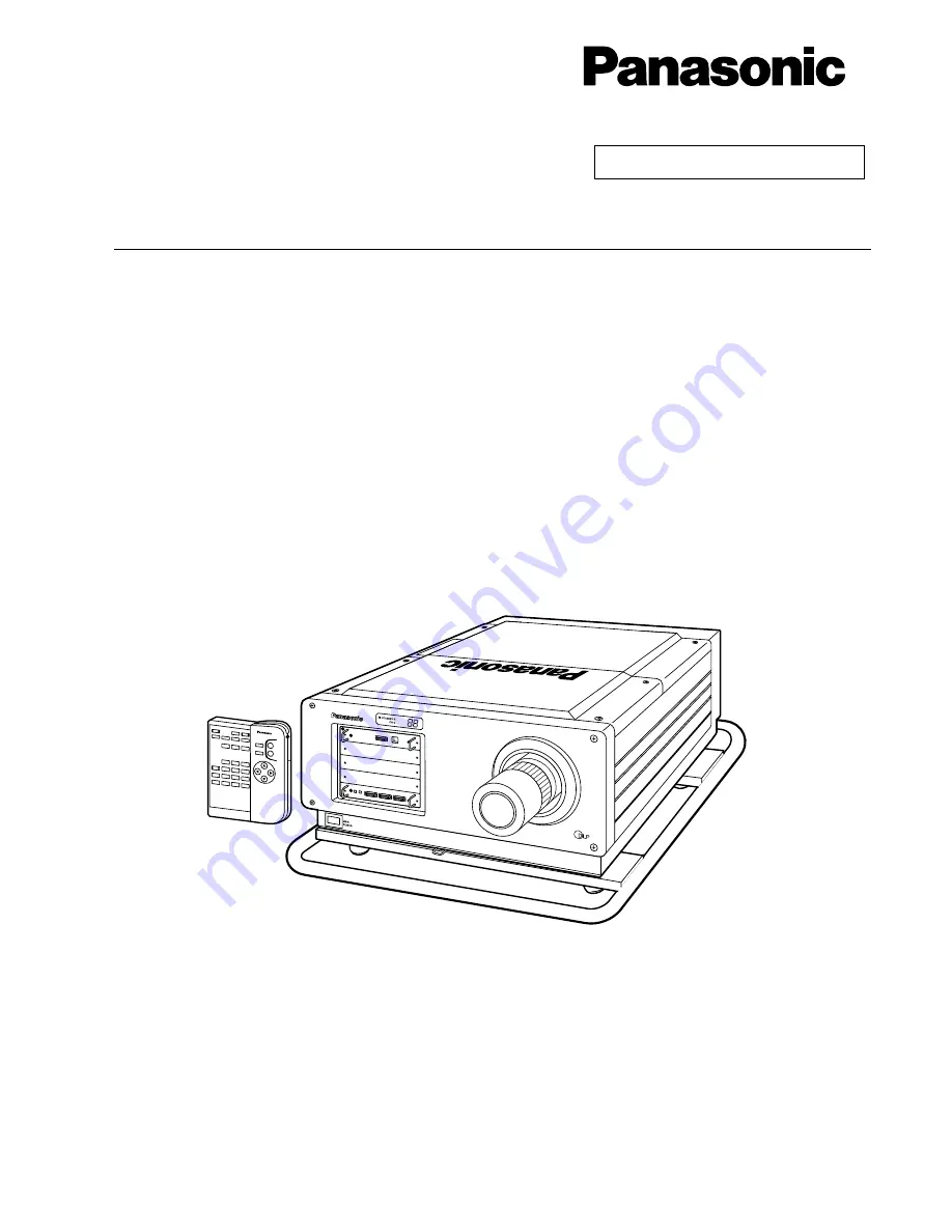
DLP™ based Projector   Commercial Use

Models No.

PT-D9510U
PT-D9610U

Read these instructions completely before operating this unit. 

TQBJ0084

Operating Instructions

®

Summary of Contents for PT-D9510U

Page 1: ...INPUT3 BRIGHT CONTRAST LENS PC MUTE ON SCREEN NEXT ID SELECT ID ALL 1 2 3 4 5 6 7 8 9 0 MENU ENTER DLP based Projector Commercial Use Models No PT D9510U PT D9610U Read these instructions completely before operating this unit TQBJ0084 Operating Instructions ...

Page 2: ...ately 20 14 Adjusting projector feet 24 15 Setting the projection method 25 16 Adjusting the lens 26 17 Installing the input module 28 18 Connecting the input module signal source 30 19 Selecting the input signal Selecting the system format 40 20 Selecting the signal of ET MD95VM2 sold separately 41 21 Registering input signal data 42 22 Using the RGB REALITY mode 46 23 Adjusting the picture autom...

Page 3: ...nd luminous control technology The unit can be controlled from a PC using a LAN interface This equipment has a function for automatically sending e mail when the equipment is abnormal so a system for remote control or central control can be easily realized The projector utilizes a DLPTM Digital Light Processing system which incorporates an 0 9 inch for the PT D9510U 1 1 inch for the PT D9610U DMDT...

Page 4: ... This function generates and displays a two digit error code to notify you if a problem occurs with operation of the projector A variety of different input sources can be used Other useful functions also included Projection lenses which are sold separately are required for the operation of this projector Please select the lenses which are best suited to the setting up location for the projector Pr...

Page 5: ...t This equipment generates uses and can radiate radio frequency energy and if not installed and used in accordance with the instruction manual may cause harmful interference to radio communications Operation of this equipment in a residential area is likely to cause harmful interference in which case the user will be required to correct the interference at his own expense CAUTION Any unauthorized ...

Page 6: ...ors Such power sources may cause interference Places with adverse ambient conditions Avoid places which are extremely dusty where oil fumes or vapor are present and where the ambient temperature is outside the range of 0 C 40 C 32 F 104 F or the ambient humidity is outside the range of 10 80 If the projector is installed in such places operating problems fire or electric shocks may result Do not c...

Page 7: ...et hands Doing so may cause electric shocks to occur Do not do anything that might damage the power cable Do not damaged the cable make any modifications to it place heavy objects on top of it heat it place it near any hot objects twist it bend it excessively or pull it To do so may cause fires and electric shocks to occur If the power cable becomes damaged have it repaired at an Authorized Servic...

Page 8: ...interference The projection distance will vary depending on the projection lens sold separately which is used Select a projection lens which is suitable for the amount of space available at the setting up location If installing the projector to the ceiling be sure to have a qualified technician carry out the work If suspending the projector from the ceiling you will need to obtain the ceiling moun...

Page 9: ...nd maintenance Always disconnect the power plug from the power source as a safety precaution before carrying out cleaning and maintenance Wipe the cabinet with a soft dry cloth If the cabinet is particularly dirty soak the cloth in water with a small amount of neutral detergent in it squeeze the cloth very well and then wipe the cabinet After cleaning wipe the cabinet dry with a dry cloth If using...

Page 10: ...T COLOR and TINT and to adjust the lens Power indicator When the MAIN POWER switch is pressed this indicator becomes red and the projector switches to standby mode When the POWER button on the remote control unit or the projector operating panel is pressed the indicator changes to green and after a brief period a picture is then projected Self diagnosis display If a problem with the operation of t...

Page 11: ...ID numbers when selecting IDs and to enter passwords PIC MUTE button This button is used to temporarily halt the projection of a picture ON SCREEN button This button is used to turn the on screen display function on and off NEXT button If the ID SELECT button is being pressed and held the tens digit of the ID number then changes each time the NEXT button is pressed ID SELECT button When the projec...

Page 12: ...button is used to accept and activate items selected in the on screen menus Control level buttons These buttons are used to adjust the BRIGHT CONTRAST COLOR and TINT and to adjust the lens LIGHT button The buttons on the front of the remote control unit will be illuminated while this button is pressed The button illumination will switch off approximately 10 seconds after this button is released Ba...

Page 13: ... should be observed in order to prevent damage to or leaking of the batteries Do not mix old and new batteries of batteries of different types Do not burn spent batteries or put them in with combustible garbage Notes when using the remote control unit Do not spill any liquids onto the remote control unit Do not drop the remote control unit Do not use rechargeable Ni Cd batteries Do not recharge th...

Page 14: ...3 Y C ON External contact control 1 2 3 4 5 6 7 8 9 D SUB9P REMOTE IN1 Terminal Projector Using REMOTE IN 1 Terminal Because each pin of the REMOTE IN 1 terminal is controlled by its open H or short L as shown in the table below the addition of an external control circuit allows the external control for the projector power supply on and off the change of the input terminal and the switching of the...

Page 15: ...pear in the self diagnosis display during the warm up After the warm up the self diagnosis display will turn off and the projector will project a picture If the ambient temperature is too low and the warm up time exceeds five minutes the power will automatically be turned off as an abnormal condition In this case increase the ambient temperature to 0 C or higher and then perform the operations Mai...

Page 16: ...POSITION OPTION SIGNAL LIST TEST PATTERN SELECT MENU START ENTER EXIT MENU LENS Lens adjustment mode POSITION Screen position adjustment mode SIGNAL LIST Registered signal list PICTURE Picture adjustment mode OPTION Miscellaneous setting mode MENU screen On screen menu operation guide On screen displays such as the input signal type will appear when the input signal is changed The display will dis...

Page 17: ...ion lens sold separately which is appropriate for the projector setting up conditions Setting procedure Remove the lens caps one each at front and back from the projection lens Insert the projection lens into the lens holder and turn it clockwise until it is securely in place Because a projection lens is considerably heavy be careful not to drop it during installation If inserting the projection l...

Page 18: ...ately on pages 20 24 2 Installing the screen and the projector Center line of screen Use a plumb line to shown where screen center line comes to Example of installation points Use a set square to get the perpendicular extension line Mark the position of projection distance Center line of screen 188 7 4 90 L Installing the screen After determining the installation position of the screen in consider...

Page 19: ...5 by the procedure below For the procedure to install to the ceiling refer to the installation instructions of the optional ceiling mount bracket ET PKD95 Put a mark on the ceiling surface at the upwardly straight point of a distance of 188 mm 7 4 from the screen center to the left Draw a line in a direction at right angles to the screen from marked point Put another mark on the ceiling surface at...

Page 20: ...5 9 5 698 18 9 6 307 20 8 7 830 25 8 9 353 30 8 10 876 35 8 12 399 40 8 13 922 45 8 15 445 50 8 16 968 55 8 18 491 60 8 5 197 17 1 6 203 20 4 7 713 25 4 9 223 30 3 10 229 33 7 12 745 41 9 15 261 50 0 17 777 58 8 20 293 66 7 22 809 77 10 25 325 83 0 27 841 91 4 30 357 99 7 5 270 17 3 6 279 20 7 7 792 25 7 9 305 30 6 10 314 33 10 12 835 42 1 15 357 50 4 17 879 58 8 20 401 66 11 22 923 75 2 25 445 83...

Page 21: ...1 10 27 700 90 10 30 448 99 10 8 942 29 4 10 698 35 1 13 332 43 9 15 966 52 4 17 722 58 1 22 112 72 7 26 502 86 11 30 892 101 4 35 282 115 8 39 672 130 1 44 062 144 6 48 452 158 11 8 922 29 3 10 692 35 1 13 346 43 9 16 001 52 6 17 771 58 3 22 195 72 10 26 619 87 3 31 043 101 10 35 467 116 4 39 892 130 10 44 316 145 4 48 740 159 10 15 409 50 6 18 497 60 8 23 128 75 10 27 759 91 0 30 847 101 2 38 56...

Page 22: ...0 7 0 1 Min Max 13 905 45 9 16 686 54 11 20 858 68 7 25 029 82 4 27 810 91 6 34 763 114 4 41 715 137 3 48 668 160 2 55 620 183 0 62 573 205 10 69 525 228 9 76 478 251 7 83 430 274 6 8 066 26 7 9 654 31 9 12 035 39 7 14 416 47 5 16 004 52 8 19 973 65 9 23 941 78 9 27 910 91 10 31 879 104 11 35 847 117 11 39 816 131 0 43 785 144 0 47 753 157 1 2 540 100 3 048 120 3 810 150 4 572 180 5 080 200 6 350 ...

Page 23: ...een inches x 1 344 5 67 Max L diagonal of screen inches x 1 785 5 157 Min L diagonal of screen inches x 1 204 5 67 Max L diagonal of screen inches x 1 6 5 157 Min L diagonal of screen inches x 1 233 5 67 Max L diagonal of screen inches x 1 638 5 157 Model No of projection lensAspect ratio 4 3 16 9 16 9 4 3 4 3 16 9 ET D95LE5 1 5 2 0 1 ET D95LE6 2 0 2 5 1 ET D95LE7 2 5 4 0 1 ET D95LE9 0 8 1 Z o o m...

Page 24: ...f calculation of Projection distance L Unit mm L 21 457 x diagonal of screen inches 252 L 23 371 x diagonal of screen inches 252 Calculation of the projection distance for each projection lens for PT D9510U If there is no reference made to the require picture size calculate the projection distance using an expression below after obtaining the diagonal measurement inch of the screen you will use Mo...

Page 25: ...e OPTION screen will be displayed Press the UP and DOWN arrow buttons to select SETTING Press the LEFT and RIGHT arrow buttons to select the projection method The display and the projection method will change as shown below each time the LEFT or RIGHT arrow button is pressed Press the MENU button twice The on screen display will disappear and the screen will return to the normal state MENU AUTO SE...

Page 26: ...the centre of the screen Initial pressing of these buttons will allow fine adjustment Pressing and holding these buttons will allow the slow mode for the first six seconds and then the fast mode Press the MENU button to return the screen to the normal state The following procedure can also be used in lens adjustment mode Press the MENU button The MENU screen will be displayed Press the UP and DOWN...

Page 27: ... 0 22H 0 24H 0 29H 0 31V 0 38V 0 38V 0 50V 0 31H 0 31H 0 50V 0 22H 0 28V 0 50V Standard projection position Projected screen height V Projected screen width H Projected screen width H Standard projection position Projected screen height V Projected screen height V Projected screen width H Projected screen height V Standard projection position Standard projection position Projected screen width H F...

Page 28: ... p p when SYNC ON G Y signal is input Composite sync Separate sync 0 6 V p p 4 0 V p p with 75 Ω TTL level with 1 kΩ Analog RGB input signal fH 15 kHz 100 kHz fV 24 Hz 120 Hz dot clock frequency 20 MHz 162 MHz Color difference input signal Applicable formats 480i 576i 480p 720 60p 1080 60i 1035 60i 1080 50i 1080 30p 1080 25p 1080 24p 1080 24sF Video Y 1 0 V p p C 0 286 V p p Cr Cb 0 7 V p p Impeda...

Page 29: ... Tighten the two screws to secure module in place Remove the slot cover Slot cover Remove the two screws Insert the input module Input module Slot Secure the input module Register input signal Tighten the two screws With this equipment it is necessary to store the input signal after installing the input module Refer to pages 42 and 43 for details on registering input signals Installing the input m...

Page 30: ...er cable RGB signal Component signal Video signal input module ET MD95VM2 Serial digital input module ET MD95SD1 TMDS input module ET MD95T Component signal SD signal TMDS signal Projector Personal computer High definition VCR DVD player VCR with built in TBC Multi laser disc player Commercial type digital VCR Personal computer HD Serial digital input module ET MD95SD3 Serial digital input module ...

Page 31: ...computer RGB signal input module sold separately ET MD95RGB RGB Module ET MD95RGB CAUTION Ternary synchronization signals cannot be input to the H H V and V terminals Do not input synchronization signals to the H H V and V terminals when SYNC ON GREEN signals are being input C means composite sync in H H V PR Cr Y PB Cb High definition VCR DVD player R PR G Y B PB H H V V PB Cb Y PR Cr RGB Module ...

Page 32: ...1 1024 768 60 0 75 0 XGA 1024 768 65 5 81 6 1024 768 68 7 85 0 1024 768i 35 5 86 8 1024 768 80 7 100 8 1024 768 94 0 120 0 1152 864 63 9 70 0 1152 864 67 5 75 0 MXGA 1152 864 77 1 85 0 1120 750 50 1 60 1 1120 750i 32 6 80 0 1280 1024 52 4 50 0 1280 1024 64 0 60 0 1280 1024 72 4 66 3 SXGA 1280 1024 78 2 71 7 1280 1024 80 0 75 0 1280 1024i 46 2 86 0 1280 1024i 47 6 88 9 MAC16 832 624 49 7 74 6 MAC21...

Page 33: ...g panel is pressed LINE input Y C input If connecting a VCR be sure to use one which has a built in TBC If applying a signal with nonstandard burst signal the picture may become unstable In this case connect a time base corrector between this module and its signal source Video signal Video signal Luminance signal Color signal Monitor TV Video signal input module sold separately ET MD95VM2 DVD play...

Page 34: ... For details of composite and component signal switching see ET MD95VM2 sold separately signal switching on page 41 Luminance signal Y Color difference signal Cb Video signal input module sold separately ET MD95VM2 DVD player LINE Cr IN C Cb IN LINE OUT Y IN Video Module ET MD95VM2 Color difference signal Cr ...

Page 35: ... 22 96 feet is used signal conditioning amplifier should also be used Before connecting the cable check to make sure that the projector and PC are turned off If cable connection is attempted with the projector and or PC turned on the PC may be damaged Concerning a connecting cable used for this module because its characteristic impedance can affect the picture performance consult a Panasonic sales...

Page 36: ...an handle two different signals with different specifications The current signal format can be checked by looking at the on screen display SD signal SD signal output Serial digital input module sold separately IN OUT Professional type digital VCR ET MD95SD1 for 480i 576i 480i Module ET MD95SD1 SERIAL Connecting the signal source to the input module for serial digital signals ...

Page 37: ...gital input module sold separately MAIN IN Professional type digital VCR ET MD95SD2 for 480p 480i 576i 480p Module ET MD95SD2 SERIAL MAIN OUT SUB IN SUB OUT MAIN Link A SUB Link B MAIN Link A SUB Link B 1 480p dual link 4 2 2p 59 94 Hz progressive scan with 720 by 483 active lines at 270 Mbps complying with the SMPTE294M Standard ...

Page 38: ...e 4 video signal formats described above can be switched from one to another with the SYSTEM SELECTOR button that cycles through those signal formats The selected input signal is indicated by an OSD message that automatically goes off The SYSTEM SELECTOR should normally be set in the AUTO position The automatic scan format identification logic may malfunction if signal connections other than those...

Page 39: ...at cycles through those signal formats The selected input signal is indicated by an OSD message that automatically goes off The SYSTEM SELECTOR should normally be set in the AUTO position The automatic scan format identification logic may malfunction if signal connections other than those described above are employed or an unstable video signal is applied In such an event use the SYSTEM SELECTOR b...

Page 40: ...put module is installed Remote control unit or R G B INPUT 1 R G B Invalid INPUT 1 Switches to slot 1 INPUT 2 Switches to slot 2 INPUT 3 Switches to slot 3 INPUT 2 INPUT 3 Projector INPUT NOTE RGB signal input module RGB RGB REALITY YPBPR When 720p or 1080i signals are input ET MD95RGB When set at AUTO1 AUTO1 NTSC PAL SECAM NTSC4 43 PAL60 When set at AUTO2 AUTO2 NTSC PAL M PAL N When set at YCbCr ...

Page 41: ...s the UP and DOWN arrow buttons to select the input signal system and press the UP and DOWN arrow buttons to select input signal format LINE or Y C or YCbCr The selected signal format will be displayed The picture may be distorted while the signal format is being switched If chose LINE or Y C in step above press the UP and DOWN arrow buttons to select the video system and press the LEFT and LIGHT ...

Page 42: ...r of available memory numbers is displayed automatically If there is no available memory number follow the overwriting procedure on the next page For the registration name NAME the signal name and memory number are displayed automatically When using the original name displayed automatically on the screen without change press the ENTER button The registration is complete and the display will return...

Page 43: ...t the signal to be cleared Press the ENTER button The SIGNAL STATUS screen will be displayed If not clearing the existing signal press the MENU button to return the display to the SIGNAL LIST screen Press the ENTER button The clearing operation is complete and the SIGNAL STATUS screen will be displayed The contents of the new signal will be displayed for each item For the remainder of this registr...

Page 44: ...A5 2 xxx60 A5 2 SELECT 1 9 EXIT MENU ENTER NEW SUB MEMORY NAME xxx60 A5 n MEMORY No A5 n S S No INPUT No 1 fH 48 30 kHz fV 60 00 Hz SYNC STATE H NEG V NEG 75 ohm YES ENTER NO MENU The basic signal name suffixed with plus the sub memory number is set as the initial value If the signal name with the suffix exceeds 12 characters the initial value is the basic signal name n is a numerical value from 2...

Page 45: ...8 Location where signal is stored Displays sub memory number 1 9 1 is the basic signal NOTE Restrictions Up to 8 sub memories can be stored for each input signal Therefore there are 9 types in total including the basic signal A total of 32 sub memories can be stored in this equipment Sub memory list Input 7680 for the PASSWORD at the OPTION MENU This displays the list of signals stored as sub memo...

Page 46: ... above list fH kHz fV Hz 15 73 60 15 63 50 31 47 60 45 00 60 33 75 60 33 75 60 27 00 24 28 12 50 33 75 30 28 12 25 27 00 48 RGB mode RGB REALITY mode Remarks RGB mode only Compatible factory default Compatible when you apply the RGB Reality mode to the signal formats marked with select the signal format with the SYSTEM SELECTOR button and then register it with the projector s memory These signal f...

Page 47: ...ustment completes correctly COMPLETED will be displayed Even if this happens there may still be some cases where the clock phase will not be correct In such cases adjust the clock phase manually Adjust according to the following page when performing automatic adjustment of special signals and wide aspect 16 9 etc signals If inputting a picture in which the edge of the screen is not known or a dark...

Page 48: ...ode input the horizontal resolution number of horizontal display dots of the signal source at DISP DOTS using the control buttons Press the ENTER button This completes the automatic adjustment NOW CALCULATION is displayed during automatic adjustment Initial input display after automatic adjustment AUTO SETUP MENU MODE USER DISP DOTS nnnn MENU SELECT START ENTER EXIT MENU MENU AUTO SETUP LENS PICTU...

Page 49: ...t TOTAL DOTS Total number of horizontal dots DISP DOTS Actually displayed number of horizontal dots TOTAL LINES Total number of vertical lines DISP LINES Actually displayed number of vertical lines Numeric values for each item are displayed according to the input signal If vertical stripes or chipped areas appear on the screen increase and decrease the displayed values to adjust the screen to its ...

Page 50: ...NTER button The CLOCK PHASE screen will be displayed Use the control level buttons and to adjust the clock phase The adjustment values will change from 0 min to 31 max If the signal output from the personal computer is itself unstable it may not be possible to obtain an optimum adjustment value If the TOTAL DOTS setting is incorrect it may not be possible to obtain an optimum adjustment value Adju...

Page 51: ...y will disappear and the screen will return to the normal state MENU AUTO SETUP LENS PICTURE POSITION OPTION SIGNAL LIST TEST PATTERN MENU SUB MENU ENTER EXIT MENU POSITION SHIFT SIZE BLK CLOCK PHASE INPUT RESOLUTION CLAMP POSITION KEYSTONE EDGE BLENDING MENU SUB MENU ENTER EXIT MENU SHIFT V 15 H 120 ADJUST EXIT MENU Adjusting the picture position If the button is pressed the picture moves to the ...

Page 52: ... SIZE BLK CLOCK PHASE INPUT RESOLUTION CLAMP POSITION KEYSTONE EDGE BLENDING MENU SUB MENU ENTER EXIT MENU BLK UPPER UPPER nnnn LOWER nnnn LEFT nnnn RIGHT nnnn SELECT ADJUST EXIT MENU If picture noise appears at the perimeter of the screen or a picture extends off the screen a little adjust the blanking to fine tune the screen If the button is pressed the blanking portion moves upward If the butto...

Page 53: ...o 254 max Optimum value for clamp position adjustment If the black sections are fractured The optimum value is when the fracturing of the black sections is at a minimum If the black sections are tinged with green Optimum value is when the green portion turns black but is not smudged The projector has a picture mute capability that allows you to put the image off instantaneously To mute the image p...

Page 54: ...n that corresponds to the projector s elevation angle to the screen to within 10 As indicated below two types of modes can be selected for keystone correction of luminance bandwidth chrominance YUV signals For the RGB system there is only keystone correction using digital processing YUV KEYSTONE REAL The original images are preserved as they are after keystone compensation thanks to digital proces...

Page 55: ... displayed by pressing the respective buttons on the remote control unit If approximately five seconds pass without any buttons being pressed while an individual adjustment screen is being displyed the display will return to the PICTURE screen MENU AUTO SETUP LENS PICTURE POSITION OPTION SIGNAL LIST TEST PATTERN MENU SUB MENU ENTER EXIT MENU PICTURE COLOR TEMP BRIGHT nnn CONTRAST nnn COLOR nnn TIN...

Page 56: ...ors do not match correctly press the STD button while one of the individual adjustment screens is being displayed Only the item being displayed will be reset to the factory pre settings The projection of a built in test pattern Refer to page 65 does not allow the white balance adjustment Be sure to project an external input signal for this adjustment Adjustingthepicturetothedesiredsetting continue...

Page 57: ...he window Use the UP or DOWN arrow button to scroll the list Press the UP and DOWN arrow buttons to step through the adjustment items list until you reach the target item Press the LEFT and RIGHT arrow buttons to change the current setting For available adjustment items and settings see the table on the next page MENU AUTO SETUP LENS PICTURE POSITION OPTION SIGNAL LIST TEST PATTERN MENU SUB MENU E...

Page 58: ...factory default 2 A larger value causes a greater effect Four steps from OFF to 3 factory default 2 A larger value causes a greater effect OFF No correction 1 Weak 2 Medium factory default 3 Strong A larger value causes a greater effect Two steps of 2 2 and 2 5 factory default 2 2 Five types from 0 to 4 factory default 2 0 Gives priority to contrast 4 Restricts the loss in picture information to a...

Page 59: ...he PT D9510U 5 4 for the PT D9610U the left and right edges of the picture are cropped HV Fit The input signal is converted to an aspect ratio of 4 3 for the PT D9510U 5 4 for the PT D9610U For signals with an aspect ratio other than 4 3 for the PT D9510U 5 4 for the PT D9610U circles in the picture become distorted etc For signals with an aspect ratio other than 5 4 circles in the picture become ...

Page 60: ... PICTURE Default Through H Fit V Fit HV Fit 8 5 640 400 4 3 1152 864 5 4 1280 1024 SIZE SETTING The picture is displayed at maximum size while maintaining the original aspect If the picture extends outside the screen the top left corner is used as the reference point ...

Page 61: ... PICTURE Default Through H Fit V Fit HV Fit 8 5 640 400 4 3 1152 864 5 4 1280 1024 SIZE SETTING The picture is displayed at maximum size while maintaining the original aspect If the picture extends outside the screen the top left corner is used as the reference point ...

Page 62: ... The on screen display will disappear and the screen will return to the normal state Power up mode HIGH is cancelled when the power is turned off Therefore the mode will return to the normal usage mode NORMAL when the power is turned back on When HIGH has been set in LAMP POWER mode the lamp s useful life will be shorter compared to normal mode Lamp power mode switching is effective only when the ...

Page 63: ...o select the mode Press the MENU button twice The on screen display will disappear and the screen will return to the normal state In the SUPER mode lamp service life is shorter than with other modes 63 Contrast switching function MENU AUTO SETUP LENS PICTURE POSITION OPTION SIGNAL LIST TEST PATTERN MENU SUB MENU ENTER EXIT MENU NORMAL HIGH SUPER CONTRAST Normal Middle Maximum BRIGHTNESS Maximum Ma...

Page 64: ...to switch the input impedance signal level of the sync signal When connecting with equipment like a signal selector whose sync output impedance is 75 ohm use 75 ohm and when connection with equipment like a PC video card whose sync output is TTL switch to TTL HI Z Switching procedure Press the MENU button The MENU screen will be displayed Press the UP and DOWN arrow buttons to select OPTION Press ...

Page 65: ... to select TEST PATTERN Press the LEFT and RIGHT arrow buttons to select the required test pattern Test pattern display chart LEFT and RIGHT arrow buttons MENU AUTO SETUP LENS PICTURE POSITION OPTION SIGNAL LIST TEST PATTERN TEST OFF STD MENU CHANGE EXIT MENU MENU screen Input picture MENU screen Focus MENU screen Convergence MENU screen Flag reversal MENU screen Flag MENU screen Window MENU scree...

Page 66: ...st temperature information Data for module in slot RGB RGB Data for module in slot 1 INPUT 1 Data for module in slot 2 INPUT 2 Data for module in slot 3 INPUT 3 MENU AUTO SETUP LENS PICTURE POSITION OPTION SIGNAL LIST TEST PATTERN MENU SUB MENU ENTER EXIT MENU SYSTEM INFORMATION ROM Ver n nn LAMP RUNTIME NORMAL nnnnnh HIGH nnnnnh REMAIN nnnnnh SET RUNTIME nnnnnh INSIDE EXHAUST RGB INPUT1 INPUT2 IN...

Page 67: ...FF using the LEFT and RIGHT arrow buttons MENU AUTO SETUP LENS PICTURE POSITION OPTION SIGNAL LIST TEST PATTERN MENU SUB MENU ENTER EXIT MENU POSITION SHIFT SIZE BLK CLOCK PHASE INPUT RESOLUTION CLAMP POSITION KEYSTONE EDGE BLENDING SELECT ADJUST ENTER EXIT MENU EDGE BLENDING UPPER OFF LOWER OFF LEFT OFF RIGHT OFF MARKER OFF SELECT ON OFF ADJUST EXIT MENU The projector is equipped with a function ...

Page 68: ...RN SELECT SUB MENU ENTER EXIT MENU NOTE COLOR MATCHING R RED nnn GREEN nnn BLUE nnn PATTERN SELECT ADJUST EXIT MENU For adjusting Effects of altering the color adjustment When altering the same color correction as the color adjustment the luminance of the color under adjustment changes When altering the RED color correction the RED component of the color under adjustment increases or decreases Whe...

Page 69: ...will return to the normal state The ID numbers can be set to ALL or to a number from 1 to 64 The ID number is set to ALL at the time of shipment from the factory When setting ID numbers the ID number of the remote control unit must match the ID number of he projector All projectors which have had their ID numbers set to ALL will operate regardless of which number is specified when using the remote...

Page 70: ...XT button or a numeric button is not pressed within 5 seconds of pressing the ID SELECT button the ID number will return to the setting prior to when the ID SELECT button was pressed Setting an ID number for the remote control unit can be carried out without needing the projector so be careful not to press the ID SELECT button inadvertently Once an ID number has been assigned to the remote control...

Page 71: ...onding to the group BAUD RATE PARITY VPS SYSTEM and GROUP are reconfigurable parameters see the page 73 This unit switches to energy saving mode when in standby to reduce energy consumption When turning the power ON from standby mode send the POWER ON 3Eh command two times When using two or more units 1 The communication settings should be the same for inputs and outputs Each IN and OUT can be adj...

Page 72: ...TM based projector STX 02h ID NO 00h PICTURE MUTE 91h ETX 03h Send PC DLPTM based projector STX 02h ID NO 1byte PICTURE MUTE 91h ETX 03h Send a PICTURE MUTE command to all the DLPTM based projectors The ID No is that of the DLPTM based projector whose VPS SYSTEM is set up for MASTER ID Code specified GROUP A 80h GROUP B 81h GROUP C 82h GROUP D 83h GROUP E 84h ID Code specified GROUP F 85h GROUP G ...

Page 73: ...232C connector MENU AUTO SETUP LENS PICTURE POSITION OPTION SIGNAL LIST TEST PATTERN MENU SUB MENU ENTER EXIT MENU RS 232C SETTING RS 232C IN BAUD RATE 9600bps PARITY EVEN RS 232C OUT BAUD RATE 9600bps PARITY EVEN VPS SYSTEM SLAVE GROUP PARITY MASTER MENU SELECT EXIT MENU RS 232C IN Pin No Name Functions 1 2 3 4 5 6 7 8 9 T R I R D S D N C F G T R O R S C S N C unassigned data transmission data re...

Page 74: ...h 7 17h 8 18h 9 19h 0 35h BRIGHT 36h CONTRAST 3Bh STD 3Dh POWER 3Eh POWER ON 2 3Fh POWER OFF 2 40h TEST 2 58h 59h 5Ah 5Bh 5Ch 5Dh 62h ON SCREEN 6Bh ID ALL 1 6Ch ID SELECT 1 6dh INPUT 2 70h SYSTEM SELECTOR 72h ENTER 7Ah MENU 7Ch LENS 91h PICTURE MUTE 1 This command is for the supplied remote control therefore would have no effect when sent from RS 232C 2 Not available for the remote control unit NO...

Page 75: ...rt function If the projector power is ON turn it OFF by pressing the remote control or on the projector POWER key and wait for approximately 5 minutes until the cooling fan stops Set the front MAIN POWER switch of the projector to OFF then unplug the projector from the supply outlet Remove the CPU module Remove the connector that connects CM6 to CM7 then use the same connector to connect CM5 to CM...

Page 76: ...ing the RS 232C OUT port into an RS 422 OUT port If the projector power is ON turn it OFF by pressing the remote control or on the projector POWER key and wait for approximately 5 minutes until the cooling fan stops Set the front MAIN POWER switch of the projector to OFF then unplug the projector from the supply outlet Remove the CPU module See Converting the RS 232C IN port into an RS 422 IN port...

Page 77: ...with the e mail server Check that e mail can be used beforehand LAN cable should be a straight type that is category 5 compatible LAN cable length to be less than 100 m Network module parts identification and function Network Module ON LINE SERIAL FUNCTION TRANSMIT RECEIVE LAN terminal 10Base T 100Base TX For connection of LAN cable Serial Input Output terminal This terminal is for the service rep...

Page 78: ...the ENTER button twice After the online lamp of the network module goes out it lights up again MENU AUTO SETUP LENS PICTURE POSITION OPTION SIGNAL LIST TEST PATTERN MENU EXIT MENU Initial setting of network module NETWORK MODULE SETTING HOST NAME PROJ01 DHCP OFF IP ADDR 192 168 0 8 NET MASK 255 255 255 0 GATEWAY 192 168 0 1 MAC ADDR 01 02 03 04 05 06 STORE MENU POSITION ADJUST 0 9 EXIT MENU OPTION...

Page 79: ...when not using a DHCP server Input a gateway address when not using a DHCP server This displays the unique media access control MAC address of the network equipment This may be necessary when using a DHCP server Host name display and setting DHCP client function IP address display and setting Net mask display and setting Gateway address display and setting MAC address display When using a DHCP ser...

Page 80: ...nasonic Projector Control at 192 168 0 8 Cancel User Name Password user1 O K TOP Panasonic projector control window Netscape File Edit View Go Window Help Copyright C 2001 Matsushita Electric Industrial Co Ltd Projector control window Power status OFF Document Done Initial set up Projector control Status information E mail set up Projector firmware up date Option Please avoid starting up multiple ...

Page 81: ...tem the page for changing passwords and initial setting of the IP address is displayed Projector control button Clicking on this option displays the projector control page Power status display This displays ON when the projector power supply is on and OFF when the projector is in standby Status information button Clicking on this option displays the projector status E mail setup button Clicking on...

Page 82: ...r Input projector name Input the host name if necessary when using DHCP server etc Projector control page This displays the projector state This displays the projector on screen The display appears even if projector on screen is set to off The on screen at the right side of the control page is updated to the most current state The projector is controlled by pressing these buttons After control the...

Page 83: ...ys projector internal temperature Displays projector exhaust temperature Displays lamp illumination remaining time Displays projector operation time Displays self diagnosis information Displays firmware version of projector main unit Displays projector type ...

Page 84: ...sent even if the warning temperature is attained again The setting temperature for temperature warning mail can be changed If this value is exceeded temperature warning mail is sent Input the e mail address to send mail to Select conditions for sending e mail Error When an error occurs in self diagnosis Warning LAMP1 When the lamp illumination remaining time reaches the time set in the column on t...

Page 85: ...lf diagnosis Warning LAMP1 When the lamp illumination remaining time reaches the time set in the column on the right side Warning LAMP2 When the lamp illumination remaining time reaches the time set in the column on the right side Warning Inside Temperature When the internal temperature reaches the value set in the column above Warning Exhaust Air Temperature When the exhaust temperature reaches t...

Page 86: ... Transfer will begin It takes a few tens of seconds for transfer to occur The time varies depending on the network situation Input the file name of the firmware to be updated Displays the current version Displays the transferred version for updating Check the current version and the update version and if there is no mistake press the Write button Rewriting will begin Do not turn off power during r...

Page 87: ...ttings such as the IP address password and e mail settings to the factory shipment condition Procedure Using the POWER button on the remote control set the unit power supply to the standby state Using an object with a pointed tip press and hold the FUNCTION switch for 3 seconds The ON LINE lamp will flash and then go out about 30 seconds later Turn off the MAIN POWER Using an object with a pointed...

Page 88: ...en This display will disappear if any of the buttons on the remote control unit or projector are pressed Warning display between 50 and 0 hours of lamp remain time The lamp remain time will be displayed in red at the bottom left of the screen for one minute After this it will repeatedly turn off for 30 minutes and then be displayed again for one minute This repeating display will be cancelled if a...

Page 89: ... does not work LAN connection to the unit is impossible Connection was denied during LAN connection to the unit Has the ON SCREEN button been pressed to turn off the displays Have the batteries been inserted with the correct polarity Is something obstructing the path between the remote control unit and the remote control signal receptor of the projector Is the remote control being used outside the...

Page 90: ... 200 5 0 m when separate fixed focus lens is fitted 4 3 when separate zoom lens or fixed focus lens is fitted 5 4 when separate zoom lens or fixed focus lens is fitted With ET MD95RGB analog RGB input module sold separately installed BNC termination 5 Video signal Sync signal input block Impedance 75 Ω 1 kΩ R PR Cr 0 7 V p p 1 0 V p p with BETACAM input G Y 0 7 V p p 1 0 V p p when SYNC ON G Y sig...

Page 91: ... input module connection slots RS 232C RS 422 input output connectors D SUB 9 pin 2 for computer control REMOTE IN 1 connector D SUB 9 pin for external control REMOTE 2 IN OUT terminals M3 pin jack 2 For wired remote control unit and serial control LAN terminal RJ 45 jack for network connection 2 5 m 8 2 Aluminium Plastic denatured 100 o 220 lb not including separate projection lens 75 3 cm 29 6 W...

Page 92: ...B input module RGB YPbPr YCbCr Video signal input module NTSC PAL SECAM NTSC4 43 PAL M PAL60 PAL N Serial digital input module 480i 576i Serial digital input module 480p 480i 576i HD Serial digital input module TMDS input module Replacement lamp unit Ceiling mount bracket Dual stacking mount bracket Visor ET D95LE1 ET D95LE2 ET D95LE3 ET D95LE5 ET D95LE6 ET D95LE7 ET D95LE8 ET D95LE9 ET MD95RGB ET...

Page 93: ...93 UNIT mm inch Dimensions 960 37 8 428 16 8 680 26 8 753 29 6 604 23 8 1051 41 4 712 28 169 6 7 114 4 5 13 0 5 φ29 1 1 332 13 1 φ50 2 ...

Page 94: ...ec mise à la terre Ceci est une précaution sécuritaire S il est impossible d insérer la fiche dans la prise s adresser à un électricien Ne pas annuler la protection de la fiche à la terre Le point d exclamation dans un triangle avertit l usager de la présence d instructions importantes concernant l utilisation et l entretien réparation dans la littérature accompagnant le produit Le symbole de la f...

Page 95: ...ts à conditions ambiantes défavorables Éviter d installer l appareil à des endroits très poussiéreux contenant des fumées grasses ou de la vapeur et où la température ambiante est hors des limites de la plage 0 C 40 C 32 F 104 F et l humidite ambiante hors des limites de la plage 10 80 Si le projecteur est installé à de tels endroits ceci pourra causer des anomalies de fonctionnement un incendie o...

Page 96: ... si la plaque de la prise murale est mal fixée ne pas les utiliser Ne pas manipuler la fiche du cordon d alimentation avec les mains mouillées On risquerait de s électrocuter Ne rien faire qui puisse endommager le câble d alimentation Ne pas endommager le câble le modifier placer d objets lourds sur le câble le chauffer le placer à proximité d objets chauds le torsader le plier excessivement ou le...

Page 97: ...ecté par des interférences électriques s il est installé près de lignes à haute tension ou près de moteurs La distance de projection varie selon la lentille de projection vendue séparément que l on utilise Choisir une lentille de projection qui convienne à la grandeur de l espace de l emplacement d installation Si l on veut installer le projecteur au plafond demander à un technicien qualifié de fa...

Page 98: ...ment sale tremper le chiffon dans de l eau avec une petite quantité de détergent neutre bien essorer le chiffon puis essuyer le boîtier Lors de l utilisation d un chiffon traité chimiquement lire les instructions accompagnant le chiffon avant l utilisation Ne pas essuyer les lentilles avec un chiffon poussiéreux ou qui produit de la peluche Si de la poussière ou de la peluche se dépose sur la lent...

Page 99: ...n bas à gauche de l écran Cet affichage disparaît si l on appuie sur toute touche de la télécommande ou du projecteur Affichage d avertissement apparaissant quand la durée de vie restante de la lampe est comprise entre 50 et 0 heures La durée de vie restante de la lampe est affichée en rouge pendant une minute en bas à gauche de l écran Elle disparaît ensuite pendant 30 minutes puis s affiche à no...

Page 100: ...egion 1707 N Randall Road E1 C 1 Elgin IL 60123 847 468 5200 WESTERN ZONE 3330 Cahuenga Blvd W Los Angels CA 90068 323 436 3500 Dallas Region 6226 Abington Way Houston TX 77008 713 802 2726 No CA Northwest Region 5870 Stoneridge 3 Pleasanton CA 925 416 5108 Government Marketing Department 52 West Gude Drive Rockville MD 20850 301 738 3840 Panasonic Sales Company Division of Matsushita Electric of ...

Reviews: