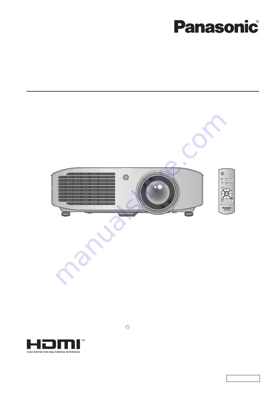
background image

LCD Projector  

Thank you for purchasing this Panasonic product.

■  Before operating this product, please read the instructions (Basic Guide / Functional Manual) carefully and 

save this manual for future use.

■ Please ensure you read the “Read this first!” (


pages


6


to


12) carefully prior to use.

Operating Instructions

Functional Manual  

ENGLISH

Model No.

PT-AR100EA

TQBJ0406

Summary of Contents for PT-AR100EA

Page 1: ...ng this product please read the instructions Basic Guide Functional Manual carefully and save this manual for future use Please ensure you read the Read this first pages 6 to 12 carefully prior to use Operating Instructions Functional Manual ENGLISH Model No PT AR100EA TQBJ0406 ...

Page 2: ...ion If this equipment does cause harmful interference to radio or television reception which can be determined by turning the equipment off and on the user is encouraged to try to correct the interference by one or more of the following measures Reorient or relocate the receiving antenna Increase the separation between the equipment and receiver Connect the equipment into an outlet on a circuit di...

Page 3: ...joy of viewing in a bright living room This projector is equipped with an exclusive mode for enjoying games and sports content at high image quality levels Harmonization with projection environment Improved brightness Wide range of picture modes Quick Steps Quick Steps See the relevant page for details 1 Set up your projector page 20 2 Connect the projector to other devices page 25 3 Connect the p...

Page 4: ...on Switching the projector on off 27 Power cord 27 Power indicator 27 Switching on the projector 28 Switching off the power 29 Projecting an image 30 Selecting the input signal 30 Adjusting the image 30 Remote control operation 31 Illuminating button lights 31 Selecting the picture mode 31 Adjusting the picture 31 Loading a saved setting 32 Displaying the VIERA LINK MENU menu 32 Displaying the wav...

Page 5: ...MENT 67 FUNCTION BUTTON 68 VIERA LINK SETTINGS 68 OTHER FUNCTIONS 70 TEST PATTERN 70 LAMP RUNTIME 70 Maintenance TEMP and LAMP Indicators 71 Managing the indicated problems 71 Care and replacement 73 Before cleaning the projector replacing components 73 Cleaning the projector 73 Component replacement 75 Troubleshooting 80 Ceiling mount bracket safeguards 81 Appendix Using VIERA Link 82 Summary of ...

Page 6: ...service personnel 3 Do not remove the earthing pin on the mains plug This apparatus is equipped with a three prong earthingtype mains plug This plug will only fit an earthing type mains socket This is a safety feature If you are unable to insert the plug into the mains socket contact an electrician Do not defeat the purpose of the earthing plug CAUTION To assure continued compliance follow the att...

Page 7: ...ere electrical shock if the cut off plug is inserted into any 13 amp socket If a new plug is to be fitted please observe the wiring code as shown below If in any doubt please consult a qualified electrician WARNING THIS APPLIANCE MUST BE EARTHED IMPORTANT The wires in this mains lead are coloured in accordance with the following code Green and Yellow Earth Blue Neutral Brown Live As the colours of...

Page 8: ...it z z excessively twist it pull it place heavy objects on top of it or wrap it into a bundle Ask an Authorized Service Center to carry out any repairs to the power cord that might be necessary Completely insert the power plug into the wall outlet and the power connector into the projector terminal If the plug is not inserted correctly electric shocks or overheating may occur and fire will result ...

Page 9: ...rheat which can cause fire or damage to the projector Do not look and place your skin into the lights emitted from the lens while the projector is being used Doing so can cause burns or loss of sight Strong light is emitted from the projector s lens Do not look or place your hands directly into this light z z Be especially careful not to let young children look into the lens In addition turn off t...

Page 10: ...ek medical advice immediately Battery fluid coming in contact with your eyes could result in loss of sight z z In this case do not rub your eyes Rinse with clean water and seek medical advice immediately Do not disassemble the lamp unit If the lamp breaks it could cause injury Lamp replacement The lamp has high internal pressure If improperly handled an explosion and severe injury or accidents wil...

Page 11: ...ld break and injury will result Be especially careful not to let young children stand or sit on the projector z z Do not place the projector in extremely hot locations Doing so will cause the outer casing or internal components to deteriorate or result in fire Take particular care in locations exposed to direct sunlight or near stoves z z Always disconnect all cables before moving the projector Mo...

Page 12: ...mpany Ltd Other names company names or product names used in these operating instructions are the trademarks or registered trademarks of their respective holders Please note that the operating instructions do not include the and TM symbols Illustrations in these operating instructions Note that illustrations of the projector may differ from the ones you actually see Page references In these instru...

Page 13: ... case and malfunctions Near high voltage power lines or near motors Doing so may interfere with the operation of the projector z z About lens focus The focus of high brightness projection lenses may not be stable immediately after turning power on due to the effects of heat from light coming from light sources Adjust lens focus 30 minutes after starting to project a video Make sure to set HIGH ALT...

Page 14: ...port Air intake port Air exhaust port 100 mm 4 or more 100 mm 4 or more z z Do not install the projector in an enclosed space If the projector needs to be installed in an enclosure provide a separate air conditioning unit or ventilating equipment Emitted heat accumulates if ventilation is insufficient This may cause the protection circuit of the projector to operate Use the front adjustable feet f...

Page 15: ...ill image for extended periods of time may lead to afterimages on LCD panels Please be aware that in some cases these afterimages may not disappear completely About optical components If using in an environment with a high temperature or where dust or tobacco smoke is present the replacement cycle of optical components such as LCD panels and polarizing plates may shorten even after less than one y...

Page 16: ...ry 2 For remote control unit CD ROM 1 TXFQB02RWEZ Attention Dispose of the packaging appropriately after removing from the product z z Contact an Authorized Service Center if you lose any of the included items z z The model number of accessories and optional accessories may be changed without prior notification z z Store small parts out of reach of infants z z Store the lens cover properly z z The...

Page 17: ...attempt to disassemble or modify the remote control z z Note Pressing buttons on the remote control when button lights is set to on illuminates the button lights z z Button lights dim if no actions are carried out after approximately 5 seconds and then extinguish if no actions are carried out after a further 5 seconds When pointed directly at the receiver on the front of the projector the remote c...

Page 18: ...tion lens Top and front view Attention Do not place your hands or objects close to the exhaust port z z Do not place hands or face near Do not place near objects that are intolerant to heat Inserting fingers may result in injury Hot air is expelled from the exhaust port and can cause burns injuries and deformation Color sensor window Air intake port Air filter cover Focus ring Adjusts the focus Zo...

Page 19: ... the power cord included Connecting terminals SERIAL Terminal for controlling the projector using a computer HDMI IN Connect HDMI signal cables COMPUTER IN Terminal for RGB signal or YCBCR YPBPR signal input from a computer COMPONENT IN Connect a color component signal cable YCBCR YPBPR ヤヰヮヱヶヵユンチチリワ ヴユンリモロ ヴノヷリュユヰチリワ ヵンリヨヨユン リワチヒ リワチビ ヒ ビ ヤヰヮヱヰワユワヵ リワ ヷリュユヰチリワ TRIGGER Trigger terminal for connecti...

Page 20: ...rojecting from front Menu Method PROJECTION METHOD FRONT CEILING Mounting on the ceiling and projecting from rear with a translucent screen Menu Method PROJECTION METHOD REAR CEILING Parts for ceiling mount optional You can install the projector on the ceiling using the optional ceiling mount bracket model no ET PKA110H for high ceilings and ET PKA110S for low ceilings Use only the ceiling mount b...

Page 21: ...0 2 28 m 7 6 4 62 m 15 2 0 15 to 1 15 m 2 29 m 90 2 57 m 8 5 5 21 m 17 1 0 17 to 1 29 m 2 54 m 100 2 87 m 9 5 5 79 m 19 0 0 19 to 1 44 m 3 05 m 120 3 45 m 11 4 6 96 m 22 10 0 22 to 1 71 m 3 81 m 150 4 33 m 14 2 8 70 m 28 7 0 28 to 2 15 m 5 08 m 200 5 79 m 19 0 11 62 m 38 1 0 37 to 2 86 m 6 35 m 250 7 25 m 23 9 14 53 m 47 8 0 47 to 3 58 m 7 62 m 300 8 71 m 28 7 17 45 m 57 3 0 56 to 4 30 m Projectio...

Page 22: ...7 Front adjustable feet and throwing angle Install the projector on a flat surface with its front side become parallel to the screen surface so that the screen becomes rectangle If the screen is tilted towards the bottom extend the adjustable feet to make a rectangle screen If the projector is tilted horizontally use the adjustable feet to level the projector As shown in the diagram the feet can b...

Page 23: ...ving the lens shift lever horizontally according to the installation position of the screen and projector Up to approximately 26 of the projection screen Up to approximately 26 of the projection screen Move the lens shift lever in direction A Screen Move the lens shift lever in direction B Vertical shift Adjust by moving the lens shift lever vertically according to the installation position of the...

Page 24: ...ion screen height SH Note Position the projector directly in front of the screen and move the lens shift lever to the center to obtain the optimum z z projection image quality When the lens shift lever is at the horizontal limit of the shift range you cannot move the lever to the vertical limit Likewise z z when the lens shift lever is at the vertical limit of the shift range you cannot move the l...

Page 25: ...nected to the projector include VIDEO S VIDEO analog RGB with TTL sync level and digital z z signal Some computer models are not compatible with the projector z z See List of compatible signals for the types of video signals that can be used with this projector z z page 86 Audio cables must be connected from each external device directly to the audio reproduction system z z Caution When connecting...

Page 26: ...te Use an HDMI High Speed cable that conforms to HDMI standards If a cable that does not meet HDMI standards is used z z video may be interrupted or may not be displayed It is possible to connect with DVI devices via an HDMI DVI conversion adapter but some devices may not project the z z image properly or other such problems could be encountered When connecting to a serial terminal see Serial term...

Page 27: ...tus of the power indicator ON G STANDBY R before operating the projector Indicator status Status No illumination or flashing Main power is switched off Red Lit Power is switched off Standby mode Press the power button to start projection Does not operate when the lamp indicator or temperature indicator is flashing Flashing Power is switched off standby mode and the POWER ON LINK is set to ON in th...

Page 28: ...s the ON side of the MAIN 3333 POWER switch to turn on the power The power indicator illuminates or flashes red z z Remove the lens cover 4444 Be sure to remove the lens cover before starting z z projection Press the power 5555 button The power indicator illuminates green after flashing z z for a while and projection starts Attention Using the projector while the lens cover is attached z z causes ...

Page 29: ...uishes and video projection halts z z The cooling fan continues to operate and the power z z indicator illuminates orange Wait for the power indicator to turn red or start flashing red Press the OFF side of the MAIN 4444 POWER switch to turn off the power Never switch off the main power or remove the z z power cord when the cooling fan is operating Note Select CANCEL or press the MENU or RETURN z ...

Page 30: ...te aspect ratio with ASPECT in the POSITION menu page 56 Adjusting the image Adjust the angle of the projector 1111 Place the projector parallel to the screen and z z then install it on a flat surface so that the screen becomes rectangle If the screen is tilted lower than the screen extend z z the adjustable feet to make a rectangle screen For details see Front adjustable feet and throwing z z ang...

Page 31: ...T button is pressed within 10 seconds of illuminating the button lights extinguish and do not automatically illuminate even if another button is pressed Selecting the picture mode You can switch to your desired picture mode settings Press The settings change as follows each time the button is pressed NORMAL DYNAMIC GAME SPORTS VIVID CINEMA CINEMA1 REC709 Note You can also switch the picture mode s...

Page 32: ...s that the waveform for each of the Y brightness R red G green and B blue values for an arbitrary number of lines from the top of the screen to the bottom is within the recommended range Enables more detailed confirmation than z z FULL SCAN Line position can be changed with the z z buttons The display position of the WAVEFORM z z MONITOR changes depending on the line position Note Signals lower th...

Page 33: ...ress to cycle through the input methods It may take time for the video to change after switching input Attention Input a signal noted in the List of compatible signals z z page 86 Note See Connecting terminals regarding input ports z z page 19 If no operations are performed for approximately 3 z z seconds the input guidance display automatically disappears If a port that has no input is selected t...

Page 34: ...reen is displayed as shown in the diagram below H POSITION 0 For items that are only names pressing the z z ENTER button displays the next screen and advanced settings can be performed Note Pressing the RETURN or MENU button when the z z menu screen is displayed returns to the previous screen Depending on the signal input some items may not be z z adjustable and some functions may not be usable So...

Page 35: ...TURE 0 38 SHARPNESS SIMPLE 38 DYNAMIC IRIS ON 38 LIGHT HARMONIZER 38 WAVEFORM MONITOR 39 SPLIT ADJUST 41 ADVANCED MENU 42 PICTURE MEMORY 53 SIGNAL MODE 54 POSITION S VIDEO IN VIDEO IN Submenu items Default setting Page H POSITION 0 55 V POSITION 0 55 ASPECT AUTO 56 WSS 1 ON 58 OVER SCAN 7 58 KEYSTONE 0 58 SCREEN AREA MEMORY 59 1 PAL signal input only COMPONENT IN COMPUTER IN Submenu items Default ...

Page 36: ...RTUP LOGO ON 64 AUTO SEARCH ON 64 HDMI SIGNAL LEVEL 1 NORMAL 64 FRAME RESPONSE NORMAL 64 PROJECTION METHOD FRONT DESK 64 TRIGGER 1 SETTING OFF 65 TRIGGER 2 SETTING OFF 65 HIGH ALTITUDE MODE OFF 66 LAMP POWER NORMAL 66 ECO MANAGEMENT 67 FUNCTION BUTTON 68 VIERA LINK SETTINGS 68 OTHER FUNCTIONS 70 TEST PATTERN 70 LAMP RUNTIME 70 1 HDMI IN only Note Display of submenu items and default settings diffe...

Page 37: ...quality VIVID CINEMA For use with a high luminance clear picture mode Note It may take a few seconds for the picture to stabilize after z z a picture mode change CONTRAST You can adjust the contrast of the colors Lower Higher Setting range 64 to 64 z z Attention Adjust the BRIGHTNESS in advance if necessary z z BRIGHTNESS You can adjust the dark black part of the projected image Darker Brighter Se...

Page 38: ...RPNESS ADVANCED 0 0 PICTURE POSITION LANGUAGE OPTION Select item with the buttons and 2222 adjust with the buttons Pressing the buttons on the screen during z z adjustment switches to the H SHARPNESS or V SHARPNESS adjustment screen H SHARPNESS V SHARPNESS 0 0 The setting range varies according to the selected z z picture mode and input signal DYNAMIC IRIS You can switch automatic adjustment of th...

Page 39: ... RGB ADJUST BLACK OFF RGB ADJUST WHITE OFF Press the buttons to switch 3333 adjustment Press the buttons to select START 4444 AUTO ADJUST and press the ENTER button PROCESSING message is displayed When z z adjustment is complete a confirmation message for applying results is displayed Select OK with the 5555 buttons Press the ENTER button 6666 Note When BLACK LEVEL ADJUST is ON the display z z sig...

Page 40: ...uttons to adjust BRIGHTNESS and then CONTRAST BRIGHTNESS Adjust the bottom line of the waveform to 0 0 or 7 5 IRE Setting range z z 32 to 32 CONTRAST Adjust the top line of the waveform to 100 100 IRE Setting range z z 64 to 64 Adjust FULL SCAN R SINGLE LINE 2222 SCAN R Set on ADVANCED MENU and use the z z buttons to adjust BRIGHTNESS R and then CONTRAST R BRIGHTNESS R Adjust the bottom line of th...

Page 41: ...FREEZE SCREEN Note Press the RETURN button and a frozen screen is z z displayed Press the ENTER button 4444 Split screen display begins z z MENU GO TO PICTURE MENU ENTER ADJUSTMENT COMPLETE RETURN GO TO AREA SELECT MENU GO TO PICTURE MENU ENTER ADJUSTMENT COMPLETE RETURN GO TO AREA SELECT When SPLIT ADJUST MODE is NORMAL When SPLIT ADJUST MODE is REVERSE Note By selecting the SPLIT ADJUST MODE wit...

Page 42: ...djust menu items that are displayed in grey z z during split adjustment The KEYSTONE of POSITION becomes inactive z z during split adjustment ADVANCED MENU You can perform more detailed image adjustment manually Press the ENTER button The ADVANCED MENU menu is displayed z z GAMMA ADJUSTMENT You can make detailed adjustments to the light intensity of each input signal level by using the ADVANCED mo...

Page 43: ...tput level of the present selected point Adjustable range depends on the input level Default setting 0 Adjust the tone with the 3333 buttons ENTER button SUB MENU button or DEFAULT button a Changing the selected point Using the remote control z z The selection point moves one point to the right each time the SUB MENU button is pressed The default setting is point 5 Ex 5 6 9 1 YADJUST POINT 0 50 10...

Page 44: ...in the Y ADJUST screen and move the selected point leftward YADJUST POINT 0 50 100 INPUT OUTPUT INPUT OUTPUT 50 0 5 YADJUST POINT 0 50 100 INPUT OUTPUT INPUT OUTPUT 44 0 5 MOVE LEFT Setting range 1 to 99 c Adjusting the output level To adjust the output level from the present setting z z press continuously until it reaches to your desired level It may be moved up and down Output level can be adjus...

Page 45: ...efault setting To set the output level on the selected point back z z to the default setting 0 press the DEFAULT button on the remote control Note Individual input levels cannot be set back to their default z z settings by pressing the DEFAULT button Press to move back themselves if needed Initialize the gamma adjustment results PICTURE POSITION LANGUAGE OPTION GAMMAADJUSTMENT ADJUSTMENT MODE GAMM...

Page 46: ...8 z z CONTRAST You can adjust color temperatures centring mainly on white R RED G GREEN B BLUE 1 1 ADVANCED MENU menu items Default setting CONTRAST R 0 CONTRAST G 0 CONTRAST B 0 Setting range 32 to 32 z z BRIGHTNESS You can adjust color temperatures centring mainly on black R RED G GREEN B BLUE 1 1 ADVANCED MENU menu items Default setting BRIGHTNESS R 0 BRIGHTNESS G 0 BRIGHTNESS B 0 Setting range...

Page 47: ...ck z z If you edit a single color to be individual different colors z z the desired color may not be achieved Adjusting the selected color when z z CURSOR is selected for ADJUSTMENT MODE Select the desired color with a cursor and adjust Press the buttons to select CURSOR 1111 in ADJUSTMENT MODE COLOUR MANAGEMENT PROFILE ADJUSTMENT MODE STARTADJUSTMENT LOG NORMAL CURSOR Press the buttons to select ...

Page 48: ...RN or MENU button to adjust the other colors Repeat from step 3 to store more adjustments Press the RETURN button or MENU 7777 button twice This returns you to the COLOUR z z MANAGEMENT menu Adjusting the selected color when z z RGBCMY is selected for ADJUSTMENT MODE Select the color from 6 different color types RED GREEN BLUE CYAN MAGENTA YELLOW and adjust COLOUR TINT and BRIGHTNESS Press the but...

Page 49: ...n ADJUSTMENT MODE is set to RGBCMY are intended to be guide colors only Editing deleting logs You can edit or delete stored logs Press the buttons to select LOG and press the ENTER button The LOG menu is displayed z z Managing the stored logs created through the z z CURSOR mode LOG ADJUSTMENT MODE PICTURE MODE POINT1 POINT2 POINT3 POINT4 POINT5 POINT6 POINT7 POINT8 ALL DELETE CURSOR NORMAL COLOUR ...

Page 50: ...red deletes them from the log Saving a log setting as a profile Save a log setting as a profile You can save up to 3 profiles Press the buttons to select PROFILE 1111 SAVE and press the ENTER button The PROFILE SAVE menu is displayed z z Press the buttons to select the number 2222 to be saved and press the ENTER button PROFILE SAVE USER1 USER2 USER3 When a profile is already saved Not saved The PR...

Page 51: ... The PROFILE NAME CHANGE menu is z z displayed PICTURE POSITION LANGUAGE OPTION PROFILE NAME CHANGE USER1 USER2 USER3 Press the buttons to select the 2222 profile name to be changed and press the ENTER button The PROFILE NAME INPUT screen is z z displayed PROFILE NAME INPUT A B C D E F G H I J K L M N O P Q R S T U V W X Y Z a b c d e f g h i j k l m n o p q r s t u v w x y z 1 2 3 4 5 6 7 8 9 0 _...

Page 52: ...ust the detail clarity system levels Reduce the effect Strengthen the effect Setting range 0 to 7 z z CINEMA REALITY You can switch the automatic image synchronizer on off for 24 frames a second images such as movies Switch settings Switch settings ON Cinema reality active OFF Cinema reality inactive Note CINEMA REALITY is effective only with interlace z z signals TV SYSTEM Only during VIDEO or S ...

Page 53: ...ICTURE POSITION LANGUAGE OPTION PICTURE MEMORY MEMORY SAVE MEMORY LOAD MEMORY DELETE MEMORY NAME CHANGE MEMORY SAVE Values set adjustment values for videos can be saved as favorites PICTURE POSITION LANGUAGE OPTION MEMORY SAVE ƭ MEMORY1 Ƭ MEMORY2 ƭ MEMORY3 ƭ MEMORY4 ƭ MEMORY5 ƭ MEMORY6 ƭ MEMORY7 ƭ MEMORY8 ƭ MEMORY9 ƭ MEMORY10 ƭ MEMORY11 ƭ MEMORY12 ƭ MEMORY13 1 2 Memory with data already stored No ...

Page 54: ...TE confirmation message is z z displayed MEMORY DELETE DELETE THE MEMORY 1 DATA CANCEL OK Select OK with the buttons 3333 Press the ENTER button 4444 MEMORY NAME CHANGE You can edit the memory name settings PICTURE POSITION LANGUAGE OPTION MEMORY NAME CHANGE MEMORY1 MEMORY2 MEMORY3 MEMORY4 MEMORY5 MEMORY6 MEMORY7 MEMORY8 MEMORY9 MEMORY10 MEMORY11 MEMORY12 MEMORY13 1 2 Press the buttons and select ...

Page 55: ...rns When the kind of striped pattern shown below is projected periodic noise sometimes occurs In such cases use the buttons to adjust to the setting with the least noise Note Clock adjustment is feasible for COMPUTER RGB z z signal input other than 480i 576i 480p and 576p Attention DOT CLOCK needs to be adjusted before adjusting the z z CLOCK PHASE CLOCK PHASE Available with signals from COMPUTER ...

Page 56: ...0p input AUTO 4 3 16 9 ZOOM JUST S16 9 576i 576p input 16 9 S16 9 14 9 ZOOM1 4 3 JUST ZOOM2 Attention If a 4 3 aspect video is projected at a 16 9 aspect ratio z z the edges may not be visible or the shape of the image may change Please project videos intended by the author for 4 3 projection at that aspect ratio Note If an aspect ratio that differs from the one used in the z z input signal is sel...

Page 57: ... the screen is reduced Enlarged horizontally Input signal Projection screen Aspect Screen ZOOM Enlarges while preserving original ratio The projected video may be clipped in some cases but the video can be accurately reproduced Use the buttons to adjust vertically Not available with HDMI signal Input signal Projection screen H FIT Adjusts horizontally to fit 16 9 Enlarged horizontally Input signal...

Page 58: ... angled surface you can correct the keystone vertically Image Operation Setting range 32 to 32 z z Note You can correct the distortion 30 degrees from the z z vertical plane However if there is overcorrection the image quality may deteriorate and become blurry For a better quality image installing the projector with minimum distortion is recommended The result of the keystone correction will affec...

Page 59: ...ustment for amount of mask and aspect settings PICTURE POSITION LANGUAGE OPTION SCREEN AREA MEMORY SAVE ƭ MEMORY1 Ƭ MEMORY2 ƭ MEMORY3 ƭ MEMORY4 ƭ MEMORY5 ƭ MEMORY6 Memory with data already stored No data stored Press the buttons to select the 1111 memory to be saved Press the ENTER button 2222 The SCREEN AREA MEMORY SAVE confirmation z z message is displayed SCREEN AREA MEMORY SAVE SAVE THE ADJUST...

Page 60: ...lect the 1111 memory name to be changed PICTURE POSITION LANGUAGE OPTION SCREEN AREA MEMORY NAME CHANGE SCREEN 1 MEMORY2 MEMORY3 MEMORY4 MEMORY5 MEMORY6 Press the ENTER button 2222 SCREEN AREA MEMORY NAME INPUT z z screen is displayed SCREEN AREA MEMORY NAME INPUT A B C D E F G H I J K L M N O P Q R S T U V W X Y Z a b c d e f g h i j k l m n o p q r s t u v w x y z 1 2 3 4 5 6 7 8 9 0 _ ALL DELET...

Page 61: ...ctly recognized if there is noise z z in the picture or external device generates noise Image size may also not be correctly recognized depending on the video Image size may not be correctly recognized if the input z z signal level from the external device is not set to the suggested value range In this case adjust the input signal level using the WAVEFORM MONITOR menu page 39 Image size may not b...

Page 62: ... side edge on the screen Less More Setting range 0 to 70 z z LOWER MASKING AREA You can place a blank mask area in the lower side edge on the screen Less More Setting range 0 to 70 z z Note If it is set to 0 each masking function will be invalid z z The MASKING AREA function will be invalid when z z adjusting the COLOUR MANAGEMENT or SPLIT ADJUST settings when displaying the TEST PATTERN or WAVEFO...

Page 63: ... guidance SIMPLE Display the name of input terminal only OSD DESIGN Set the color of the on screen menu Switch settings Switch settings TYPE1 Display using normal design TYPE2 Display using black and white design OSD POSITION You can change the displaying position of the on screen menu Switch settings Switch settings CENTRE Display in the center of the projection screen LOWER LEFT Display in the b...

Page 64: ...work correctly with some external devices z z and problems such as video not being displayed may occur FRAME RESPONSE Switch this setting when a progressive signal is input and you wish to reduce the time taken from the signal being input to the video being displayed on the screen Switch settings Switch settings NORMAL Prioritizes the image quality FAST Prioritizes the frame response Note NORMAL a...

Page 65: ...EN AREA MEMORY 6 BLANK DELAY TIME INPUT POWER ON OFF SELECT 4 3 ASPECT SELECT 16 9 ASPECT SELECT S16 9 ASPECT SELECT JUSTASPECT SELECT ZOOM ASPECT SELECT H FITASPECT SELECT V FITASPECT RS 232C COMMAND LINK 0 SEC BLANK PICTURE POSITION LANGUAGE OPTION Press the buttons to select 2222 the input output function and press the ENTER button Function settings z z OFF Unable to transmit the trigger output...

Page 66: ...e power z z source for other devices The projector will not accept trigger input while preparing z z to project after the power has been switched on and while preparing to shutdown after projection Input trigger signals after projection starts or after entering standby mode 12 V cannot be output from the trigger terminal when the z z projector is in standby mode HIGH ALTITUDE MODE Set to ON when u...

Page 67: ...K DETECTION cannot be set AUTO POWER SAVE Sets whether the functions AMBIENT LIGHT DETECTION SIGNAL DETECTION and BLANK DETECTION are active Switch settings Switch settings ON Energy saving settings active OFF Energy saving settings inactive Note Settings cannot be made when LAMP POWER is set to z z ECO AMBIENT LIGHT DETECTION You can adjust the lamp power in accordance with brightness of the inst...

Page 68: ...UTTON Display the function currently assigned to the FUNCTION button of the remote control Also cancel the assigned function How to cancel function assignment Press the ENTER button 1111 The FUNCTION BUTTON confirmation message z z is displayed FUNCTION BUTTON FUNCTION BUTTON IS DISABLED CANCEL OK Select OK with the buttons 2222 Press the ENTER button 3333 Note See Using the FUNCTION button in Rem...

Page 69: ... z not be switched off depending on their status currently recording etc STANDBY POWER SAVE Specify whether or not to switch the mode of external devices to the mode with minimum power consumption when the projector is set to standby Switch settings Switch settings OFF Do not switch ON Switch the mode of external devices to the mode with minimum power consumption Note This function works when POWE...

Page 70: ...ton to escape from the blank mode z z VIERA LINK MENU You can operate an HDMI connected device Press the ENTER button The VIERA LINK MENU menu is displayed z z VIERA LINK CONTROL Selects the device to operate and switches input HOME CINEMA VOLUME Adjusts the cinema volume HOME CINEMA MUTE Mutes the cinema OPERATE OTHER DEVICE Operates third party device For details see Using VIERA Link z z page 82...

Page 71: ...g red when power is turned off projection stops automatically z z Problem The temperature inside and or outside the projector is abnormally high Cause The air intake and exhaust ports may be obstructed The room temperature may be too high The air filter unit may be excessively dirty and ventilation may be poor The projector may be being used at high elevations 1 400 m or more above sea level Solut...

Page 72: ... is displayed when power is turned on The power may have been turned on immediately after being turned off Lamp circuit failure abnormal function or lamp unit is damaged Solution Replace the lamp unit page 77 Let the lamp unit cool down and turn on the power Press the OFF side of the MAIN POWER switch to turn off the power as described in the Switching off the power procedure page 29 and contact y...

Page 73: ...ith a clean soft and dry cloth Do not use a fluffy rag or a greasy wet or dirty z z cloth Do not rub the lens harshly as this may damage the z z surface Attention The lens is made of glass It may break or crack if struck z z with a hard object or rubbed harshly Please be careful when handling the lamp Air filter unit If too much dust accumulates in the air filter the internal temperature of the pr...

Page 74: ... engraved into the air filter frame UP until it clicks into place Attach the air filter cover and firmly 5555 tighten the air filter cover fixing screw one with a Philips screwdriver Attention The air filter unit must always be installed in the projector z z Failure to do so will result in malfunctions due to foreign materials such as dust entering the projector Do not use water to wash the air fi...

Page 75: ...tly before replacing wait one hour or longer z z The lamp cover gets very hot and contact with it can cause burns Before replacing the lamp unit A Phillips screwdriver is necessary when carrying out z z replacement Hold the screwdriver firmly The light source lamp is a glass component If it is hit on a hard z z object or dropped breakage may occur Be careful when handling a light source lamp Do no...

Page 76: ...ing increases after 2 000 hours the lamp automatically turns off On screen REPLACE LAMP Lamp indicator Over 1 800 1 hours The message is displayed for 30 seconds If you press any button within the 30 seconds the message disappears Illuminates red including when in standby mode Over 2 000 1 hours The message is displayed until you press any button 1 This is the time value for when the lamp is used ...

Page 77: ... at the front corner 3333 of the top cover of the projector and push up to open When the projector is mounted on the ceiling stand at the lens side of the projector when opening closing the top cover Top cover Protrusion Attention Be careful not to open the top panel too far For what z z to do if the top panel comes off see Attaching the top cover page 79 Use a Philips screwdriver to unscrew 4444 ...

Page 78: ... First insert the electrostatic filter white into the z z center of the case ensuring that its edges do not ride on top of the ribs and then insert the air filter black so that its four corners are within the case before attaching the air filter frame Take care so that the air filter does not get caught between the air filter frame and the case Align the catches and protrusions on the air filter c...

Page 79: ...splayed z z LAMP RUNTIME LAMP RUNTIME RESET CANCEL OK Select OK with the buttons and 22222 then press the ENTER button LAMP RUNTIME is reset to 0 and the projector z z powers off After a short while the projector enters standby mode Attaching the top cover Hold the top cover as shown in the diagram below align the hinge with the support and while pushing the arm in the direction of the arrow towar...

Page 80: ...ector may not be adjusted correctly z z 37 The remote control does not work The batteries may have run out z z The batteries may not have been inserted correctly z z The remote control signal receiver on the projector may be obstructed z z The remote control may be out of the range of operation z z Fluorescent lights may be interfering z z 17 17 17 The picture does not display correctly TV SYSTEM ...

Page 81: ... using a ceiling z z mount bracket which is not purchased from an authorized distributors or environmental conditions Unused ceiling mount brackets should be removed promptly by a qualified technician z z Be sure to use a torque driver Do not use an electrical screwdriver or an impact screwdriver z z See the installation instructions of the ceiling mount bracket for details z z The model number of...

Page 82: ...trol the menu of the connected device by projector remote control page 84 2 2 2 Speaker control 1 When POWER ON LINK page 69 is ON the input of this projector is automatically switched when playback on external devices such as a DIGA begins 2 Available with a device which has HDAVI Control 2 or later function 3 Available with a device which has HDAVI Control 4 or later function Note Do not use a c...

Page 83: ...ome functions will not be able to perform even if the versions are the same VIERA Link HDAVI Control based on the control z z functions provided by HDMI which is an industry standard known as HDMI CEC Consumer Electronics Control is a unique function that we have developed and added As such its operation with other manufacturers equipment that supports HDMI CEC cannot be guaranteed Please refer to...

Page 84: ...RA LINK MENU RETURN SELECT ENTER The menu of the accessed device appears The input mode switches automatically Use the menu of the device 4444 You can use the controls of the projector as z z well as the buttons on the remote control The functions that you can use depend on the connected device If you access a device other than a VIERA Link device VIERA LINK CONTROL RECORDER 1 The type of the conn...

Page 85: ...trol 5 is the latest Panasonic standard current z z as of August 2011 for HDAVI Control compatible devices HOME CINEMA MUTE You can mute cinema speakers using the projector remote control If you cannot mute the speakers check the settings z z of the device Select HOME CINEMA MUTE with the 1111 buttons VIERA LINK CONTROL HOME CINEMA VOLUME HOME CINEMA MUTE OPERATE OTHER DEVICE RECORDER VIERA LINK M...

Page 86: ...5 VGA85 640 480 43 3 85 0 36 0 SVGA SVGA56 800 600 35 2 56 3 36 0 SVGA60 800 600 37 9 60 3 40 0 SVGA72 800 600 48 1 72 2 50 0 SVGA75 800 600 46 9 75 0 49 5 SVGA85 800 600 53 7 85 1 56 3 XGA XGA60 1 024 768 48 4 60 0 65 0 XGA70 1 024 768 56 5 70 1 75 0 XGA75 1 024 768 60 0 75 0 78 8 XGA85 1 024 768 68 7 85 0 94 5 MXGA MXGA70 1 152 864 64 0 70 0 94 2 MXGA75 1 152 864 67 5 74 9 108 0 1 280 720 1 280 ...

Page 87: ...ettings Signal level RS 232C Character length 8 bits Sync method Asynchronous Stop bit 1 bit Baud rate 9 600 bps X parameter None Parity None S parameter None Basic format STX Command Parameter ETX Start byte 02h 1 byte End 03h 3 bytes 1 byte 4 bytes Data streaming from the computer will start with STX and proceed to command parameter and end with ETX Parameters can be added as necessary Attention...

Page 88: ...default setting page 32 OFZ FREEZE Freezes the projected screen page 70 0 OFF 1 ON FC1 FUNCTION BUTTON Activates the function allocated to the FUNCTION button of the remote control OSH BLANK Turns off the projection temporarily Sends the command to switch between ON and OFF page 70 Do not rapidly switch between ON OFF While the BLANK function is ON it is switched OFF when any command is received O...

Page 89: ...0 00000 LOW TROI0 00001 HIGH TRIGGER 2 OUTPUT Switches TRIGGER 2 OUTPUT when RS 232C COMMAND LINK is set in the TRIGGER 2 SETTING menu TROI1 00000 LOW TROI1 00001 HIGH Inquiry commands Command Control contents Parameter QPW Power status 000 OFF 001 ON QIN INPUT signal status CP1 COMPONENT IN SVD S VIDEO IN VID VIDEO IN HD1 HDMI 1 IN HD2 HDMI 2 IN RG1 COMPUTER IN QPM PICTURE MODE status NOR NORMAL ...

Page 90: ... 32 F 95 F Humidity 20 80 no condensation Scanning frequency 2 for RGB signal Horizontal scanning frequency 15 kHz 74 kHz Vertical scanning frequency 24 Hz 85 Hz Dot clock frequency Less than 154 MHz COMPONENT YPBPR signals 525i 480i 625i 576i 525p 480p 625p 576p 750 720 60p 750 720 50p 1 125 1 080 60i 1 125 1 080 50i 1 125 1 080 60p 1 125 1 080 50p 1 125 1 080 24p Color system 7 NTSC NTSC 4 43 PA...

Page 91: ...I connector HDCP HDAVI Control Ver 5 compliant SERIAL 1 set D sub 9 pin RS 232C compatible TRIGGER 2 sets monaural mini jack DC 12 V max 100 mA Selectable for input and output by menu operation Cabinet Moulded plastic PC ABS Dimensions Width 470 mm 18 1 2 Height 151 mm 5 15 16 Depth 380 mm 14 31 32 Weight Approx 8 6 kg 18 96 lbs 2 Certifications EN60950 1 EN55022 EN61000 3 2 EN61000 3 3 EN55024 Re...

Page 92: ...Specifications 92 ENGLISH Appendix Dimensions Unit mm 470 18 1 2 140 5 1 2 60 2 3 8 14 9 16 345 13 19 32 35 1 3 8 151 5 15 16 100 3 15 16 137 5 13 32 ...

Page 93: ...62 Lens shift 23 LIGHT HARMONIZER 38 Loading a saved setting 32 LOWER MASKING AREA 62 M MEMORY DELETE 54 MEMORY EDIT 60 MEMORY LOAD 54 59 MEMORY NAME CHANGE 54 MEMORY SAVE 53 59 MENU 34 Menu list 35 Menu navigation 34 MOTION EFFECT 47 MPEG NR 46 N NR 46 O ON SCREEN DISPLAY 63 OPTION 36 Optional accessories 16 OSD DESIGN 63 OSD POSITION 63 OTHER FUNCTIONS 70 OVER SCAN 58 P Part replacement 73 PICTU...

Page 94: ...Corporation 2011 M1011KM0 KI Information on Disposal in other Countries outside the European Union These symbols are only valid in the European Union If you wish to discard this product please contact your local authorities or dealer and ask for the correct method of disposal ...

Reviews: