


Reviews:
No comments
Related manuals for NN-8508
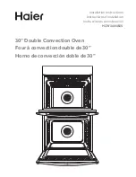
HCW3485AES
Brand: Haier Pages: 24

250 FSE
Brand: J&R MANUFACTURING Pages: 56

NS-MW09RD7
Brand: Insignia Pages: 21

K45548
Brand: Oster Pages: 3

ME1510X
Brand: Brandt Pages: 23

KOR-6N4R
Brand: Daewoo Pages: 17

3MWB-25BTCGX
Brand: Fagor Pages: 68

Mini Oven UK 06/05
Brand: Dualit Pages: 8

VM12AB
Brand: Magic Chef Pages: 23

BO638.5SS
Brand: Baumatic Pages: 40

HM-1035P
Brand: Sammic Pages: 44

DCL 08 CB
Brand: Hotpoint Pages: 40

CS1601A
Brand: HOFFEN Pages: 30

ZX6511C
Brand: Atag Pages: 32

OE606X
Brand: Blanco Pages: 19

M13R42N2
Brand: NEFF Pages: 3

NV70 77 Series
Brand: Samsung Pages: 180

ZKD 4050 B
Brand: Electrolux Pages: 20


