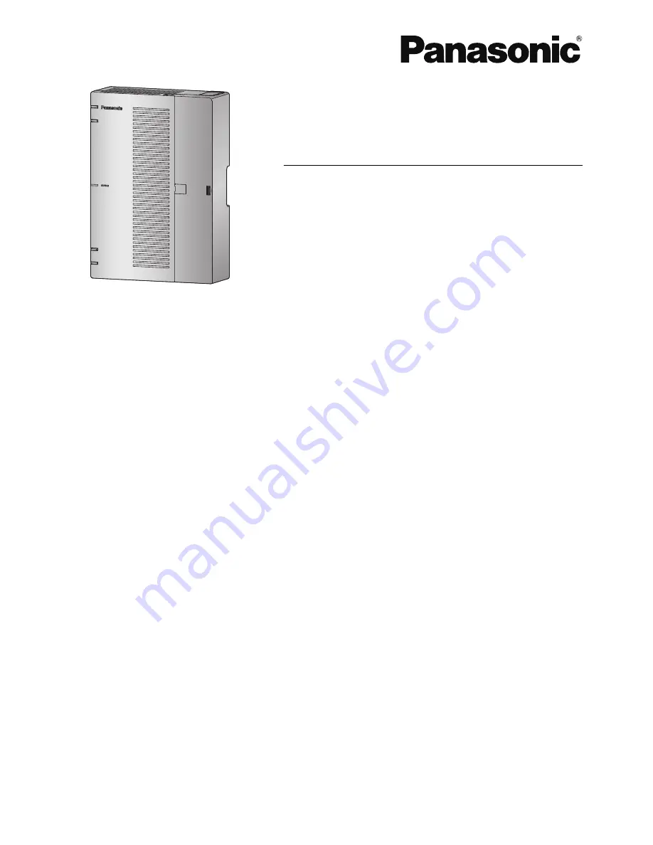
background image

Getting Started

Hybrid IP-PBX

Model No.

KX-HTS824

KX-HTS32

Thank you for purchasing this Panasonic product.
Please read this manual carefully before using this product and save this manual for future use.
In particular, be sure to read "1.1 For Your Safety, page 8" before using this product.
 

KX-HTS: Series (KX-HTS824 KX-HTS32) : PJMPR Software File Version 001.00000 or later

 
Manuals and supporting information are provided on the Panasonic Web site at:
http://www.panasonic.net/pcc/support/pbx/

Summary of Contents for KX-HTS824

Page 1: ... before using this product and save this manual for future use In particular be sure to read 1 1 For Your Safety page 8 before using this product KX HTS Series KX HTS824 KX HTS32 PJMPR Software File Version 001 00000 or later Manuals and supporting information are provided on the Panasonic Web site at http www panasonic net pcc support pbx ...

Page 2: ...X features may not be available depending on the type of telephone Under power failure conditions the connected telephones may not operate Please ensure that a sepa rate telephone not dependent on local power is available for emergency use Prior to connection of this product please verify that the intended operating environment is supported Satisfactory performance cannot be guaranteed for the fol...

Page 3: ... P SIP Panasonic SIP Phones KX HDV series System Components 3 ...

Page 4: ...nance procedures Section 6 Troubleshooting Provides information on the PBX and telephone troubleshooting Section 7 Appendix Provides information about System Prompt Languages and the revision history About the Other Manuals In addition to this Manual the following manuals are available Programming Item List PI Provides step by step instructions for performing system programming using a PC Feature ...

Page 5: ...2 3 1 Removing Attaching the Cable Cover 44 3 2 4 Frame Earth Connection 44 3 2 5 Installing Removing the Optional Service Cards 45 3 2 5 1 Slot covers 49 3 2 6 Securing the Cables 50 3 2 7 Placing the PBX on a Desktop 52 3 2 8 Wall Mounting 53 3 2 9 Surge Protector Installation 56 3 2 10 Backup Battery Connection 58 3 3 The Mother Board and Option Cards 60 3 3 1 Mother Board 60 3 3 2 LCOT4 Card K...

Page 6: ... LAN Connection 87 3 12 2 Wireless LAN Connection 88 3 13 WAN Connection 90 4 Confirming Connections 91 4 1 Making and Receiving Calls 92 4 1 1 Calling Another Extension 92 4 1 2 Calling an Outside Party 92 4 1 3 Answering Calls 92 5 Maintenance 93 5 1 System Data Backup and Restore 94 5 2 Software Upgrading 95 5 3 System Initialisation Procedure 96 6 Troubleshooting 97 6 1 Troubleshooting 98 6 1 ...

Page 7: ...Section 1 Safety Precautions This section provides important information intended to prevent personal injury and property damage 7 ...

Page 8: ...d result in injury or damage to property The following types of symbols are used to classify and describe the type of instructions to be ob served This symbol is used to alert users to a specific operating procedure that must not be performed This symbol is used to alert users to a specific operating procedure that must be followed in order to operate the unit safely Notice Panasonic assumes no re...

Page 9: ...be disassembled or modified Disassembly or modifi cation can cause a fire electric shock or damage to the product Follow all warnings and instructions marked on the product Small objects such as the screws pose a choking hazard Keep small objects out of reach of children Products that require a power source should only be connected to the type of electrical power supply specified on the product la...

Page 10: ...the power supply cord immediately and re turn the unit to your dealer To prevent fires electric shock injury or damage to the product be sure to follow these guidelines when performing any wiring or cabling a Before performing any wiring or cabling unplug the product s power cord from the outlet After com pleting all wiring and cabling plug the power cord back into the outlet b When laying cables ...

Page 11: ... pin AC plug including the earthed pin A lithium battery is used in the main unit There is a risk of explosion if the battery is replaced with an incorrect type Dispose of used batteries according to the manufacturer s instructions Consult the manufacturer of any personal medical devices such as pacemakers or hearing aids to de termine if they are adequately shielded from external RF radio frequen...

Page 12: ...ts of the mother board Doing so may result in damage to the PBX Once you have started the PBX if you unplug the PBX do not initialise it again as described in System Initialisation Procedure Otherwise your programmed data will be cleared To restart the PBX refer to 6 1 4 Restarting the PBX Before touching the product PBX cards etc discharge static electricity by touching ground or wearing an earth...

Page 13: ...ake sure that the PBX is placed as indicated in 3 2 7 Placing the PBX on a Desktop Do not place it on its side or upside down Performing surge protection is essential Make sure to follow the instructions in 3 2 9 Surge Protector Installation It is strongly recommended to use TLS encrypted communication when the PC is accessing the PBX via the Internet To use TLS encryption routers must have a port...

Page 14: ...here may be a problem with the trunk that the SLT is con nected to Contact your telephone company If all SLTs operate properly there may be a problem with your PBX Do not reconnect the PBX to the trunks until it has been serviced by an authorised Panasonic Factory Service Centre 1 1 For Your Safety 14 ...

Page 15: ...he following Do not use the product near water for example near a bathtub wash bowl kitchen sink or laundry tub in a wet basement or near a swimming pool Avoid using wired telephones during an electrical storm There is a remote risk of electric shock from lightning Do not use a telephone in the vicinity of a gas leak to report the leak SAVE THESE INSTRUCTIONS 1 2 Important Safety Instructions 15 ...

Page 16: ...tems please contact your local authorities or dealer and ask for the correct method of disposal Note for the battery symbol bottom two symbol examples This symbol might be used in combination with a chemical symbol In this case it complies with the requirement set by the Directive for the chemical involved For users in New Zealand only This equipment shall not be set to make automatic calls to the...

Page 17: ...iples enumerated in the Privacy Act 1993 shall be complied with in respect to the nature of the personal information collected the purpose for its collection how it is used and what is disclosed to any other party The SLT ports are not specifically designed for 3 wire connected equipment 3 wire connected equip ment might not respond to incoming ringing when attached to these ports For users in Aus...

Page 18: ...d the possible dangers if they become known to others 3 The PBX has default passwords preset For security change these passwords the first time that you programme the PBX 4 Change the passwords periodically 5 It is strongly recommended that passwords of 10 numbers or characters be used for maximum pro tection against unauthorised access For a list of numbers and characters that can be used in sys ...

Page 19: ...ir or handing it over to a third party a Make a backup of data stored on the System memory 5 When user information is sent from the PBX to a PC or a USB memory device the confidentiality of that information becomes the responsibility of the customer Before disposing of the PC or the USB memory device ensure that data cannot be retrieved from it by formatting the hard disk and or rendering it physi...

Page 20: ... company may request that you disconnect the equipment until the problem is re solved 6 Connection to Party Line Connection to party line service is subject to state tariffs Contact the state public utility commission public service commission or corporation commission for information 7 Combined Use with Alarm Equipment If your home has specially wired alarm equipment connected to the telephone li...

Page 21: ...s they are established will restrict the customer and the customer s employees from gaining access to the network and to these codes KEEP THE SOFTWARE UP TO DATE WITH THE LATEST DATA RF Exposure Warning This product complies with FCC radiation exposure limits set forth for an uncontrolled environment To com ply with FCC RF exposure requirements this product must be installed and operated in accord...

Page 22: ...1 5 F C C REQUIREMENTS AND RELEVANT INFORMATION 22 ...

Page 23: ...Section 2 System Outline This section provides general information on the PBX including the system capacity and specifications 23 ...

Page 24: ...2 1 Basic System Construction 2 1 1 System Configurations Main Unit The main unit contains a mother board for controlling PBX functions 2 1 Basic System Construction 24 ...

Page 25: ...ram WAN PBX Switching Hub LAN Doorphone Door Opener SLT Fax Machine Battery PC IP Network Analogue Trunk SIP Phone 1 Smartphone Softphone IP Softphone 1 SIP Phone Panasonic SIP Phone is included 2 1 2 System Connection Diagram 25 ...

Page 26: ...J45 RJ45 RJ45 USB1 PSTN 8 ports 24 ports AC Input DC Battery input FG 8 ports Main PBX LCOT4 SLC8 CPU LCOT4 SLC8 AC DC Unit L2SW Wi Fi DSP RJ11 RJ11 RJ11 RJ11 SIP Trunk Internet LCOT4 SLC8 SLC8 DPH2 Option card 2 1 3 Block Diagram 26 ...

Page 27: ...infrastructure Router PBX IP Network Analogue Trunk SLT SLT Smartphone Softphone SIP Phone LAN WAN SIP Phone PC PC Switching Hub Notice Refer to the following when the internal DHCP server will be used For details about DHCP server settings refer to Network Configuration 4 2 LAN Settings DHCP Mode in the Programming Item List 2 1 4 Typical Network Setting Example 27 ...

Page 28: ...ol DHCP Server Description The PBX has a built in DHCP server When the DHCP server is enabled the PBX will auto matically assign IP addresses to other devices on the network Using a DHCP server simplifies network management by removing the need to assign IP ad dresses to devices manually Notice If an external DHCP server is in use the DHCP Server feature of the PBX must be disabled 2 1 4 Typical N...

Page 29: ...For details about DHCP server settings refer to Network Configuration 4 2 LAN Settings DHCP Mode in the Programming Item List 2 1 4 Typical Network Setting Example 29 ...

Page 30: ...Router WAN LAN SLT SLT PBX Smartphone Softphone SIP Phone SIP Phone PC PC Notice Refer to the following when the internal DHCP server will be used For details about DHCP server settings refer to Network Configuration 4 2 LAN Settings DHCP Mode in the Programming Item List 2 1 4 Typical Network Setting Example 30 ...

Page 31: ... CO interface with Caller ID LCOT4 KX HT82470 8 Port Single Line Telephone Extension Card 8 ports Standard Telephone Line Interface with Caller ID Message waiting Lamp SLC8 KX HT82460 2 Port Doorphone Door Opener Card 2 ports Panasonic Proprietary Door phone Interface with door opener no sensor interface DPH2 2 2 Optional Equipment 31 ...

Page 32: ... selectable Operating Environment Temperature 0 C to 40 C 32 F to 104 F Humidity 10 to 90 non condensing LAN Port WAN port 10BASE T 100BASE TX 1000BASE T WAN LAN port LAN port Wireless LAN Antenna Built in antenna Transmission method 2 x 2 MIMO Communication standard IEEE802 11n b g Frequency range centre frequency Channel For North America Latin America Taiwan 2 412 GHz 2 462 GHz 1 11ch For all o...

Page 33: ...lots The PBX supports the following type and number of slots Items Maximum Number Remarks Total Trunk Channel Port 8 SIP Trunk Channel 8 Analogue Trunk Port 8 1 LCOT4 option card is required Total Extension Channel Port 24 SIP Extension Channel 24 Include softphone for smartphone or Parsonal Computer Analogue Extension Port 24 2 MCSLT8 option cards are required Wireless LAN access point 1 Target t...

Page 34: ... Card Slot D Trunk Doorphone Card Slot Maximum Optional Service Cards The following number of card can be installed in the Physical Slots or Virtual Slots of the PBX Note Any card that exceeds the capacity of the PBX will be ignored When the PBX starts up with an invalid configuration some cards will be ignored Slot Slot type Card Name Maximum Number Pre installed LCOT4 1 SLC8 1 2 3 3 System Capac...

Page 35: ...nks is G 711 Some countries such as South Africa use G 729 In this chart IP extensions are using G 711 Case Connection DSP Resource count SIP trunk G711 DSP Resource Count SIP trunk G729 1 TDM Trunk TDM Trunk 0 TSW 0 TSW 2 TDM Trunk TDM Extension 0 TSW 0 TSW 3 TDM Trunk IP Extension 1 DSP 1 DSP 4 TDM Trunk Others 1 DSP 1 DSP 5 SIP Trunk SIP Trunk 1 0 P2P 2 DSP 1 0 P2P 2 DSP 6 SIP Trunk TDM Extensi...

Page 36: ...2 3 3 System Capacity 36 ...

Page 37: ...edures to install the PBX Detailed instructions for planning the installation site installing the main unit and optional service cards and cabling of peripheral equipment are provided Fur ther information on peripheral equipment installation is included 37 ...

Page 38: ...uring installation Installation Precautions The PBX can be mounted on a wall or placed on a desktop and should be installed in an accessible loca tion where it can be easily inspected and maintained To prevent malfunction noise or discolouration follow the instructions below WARNING Do not install the system in the following locations Areas where shocks or vibrations are frequent or strong Such ac...

Page 39: ...e protectors For details refer to 3 2 9 Surge Protector Installa tion Notice Use 1 pair telephone cables when connecting SLTs data terminals answering machines comput ers etc Mis wiring may cause the PBX to operate improperly Refer to Installation when wiring the system If an extension does not operate properly disconnect the telephone from the extension line and con nect it again or turn off the ...

Page 40: ...p band Screw 2 For Wall Mounting Washer 2 For Wall Mounting 3 2 2 Names and Locations A B C D E F M L G H I J K S O N P A STATUS Indicator B Initialize Switch C WPS Switch D Power Switch E Cable Cover F Trunk Doorphone Free Slot G CO4 Interface H USB Port I WAN1 port J LAN2 WAN2 port 3 2 Installation of the PBX 40 ...

Page 41: ...The front cover is open R Q 3 2 3 Opening Closing the front cover Opening the front cover CAUTION Before opening the front cover the AC power cord must be removed from the AC inlet Do not open the front cover soon after turning off the power There is a risk of receiving burns 1 Confirm that the power switch is turned off A 3 2 3 Opening Closing the front cover 41 ...

Page 42: ...screws anticlockwise to loosen them 4 Disconnect the power cable Note In order to turn off the PBX s power a system shutdown using Web Maintenance Console must first be performed For details refer to 5 4 System Control System Shutdown in the Programming Item List 3 2 3 Opening Closing the front cover 42 ...

Page 43: ...ont cover Closing the front cover 1 Close the front cover 2 Turn the screws clockwise to tighten them 3 Slide in the cable cover and turn the screws clockwise to tighten them 3 2 3 Opening Closing the front cover 43 ...

Page 44: ...cable cover open at about a 90 angle remove the front cover by pushing it in the direction of the arrow as shown below Attaching the Cable Cover 1 Fit the cable cover to the main unit as shown below and then close the cable cover CAUTION For safety reasons fix the front cover and cable cover of the PBX with screws 3 2 4 Frame Earth Connection 1 Loosen the screw 2 Insert an earthing wire user suppl...

Page 45: ...must be more than 0 75 mm2 or 18 AWG Note Be sure to comply with applicable local regulations e g laws guidelines 3 2 5 Installing Removing the Optional Service Cards CAUTION Before touching the product PBX cards etc discharge static electricity by touching ground or wearing an earthing strap Failure to do so may cause the PBX to malfunction due to static electrici ty When installing or removing t...

Page 46: ...ree slots for extension cards you can install one or more of the following card SLC8 For details refer to the description of each optional service card in 3 3 2 LCOT4 Card KX HT82480 3 3 3 SLC8 Card KX HT82470 and 3 3 4 DPH2 Card KX HT82460 A B B A Trunk Doorphone Card Slots B Extension Card Slots 1 Remove the dummy cover plate for the Free slot Cut off any excess plastic in order to make the surf...

Page 47: ...late 1 Cut here Correct Incorrect Note When removing the dummy cover plate use plastic nippers We do not recommend using a knife such as a retractable utility knife 3 2 5 Installing Removing the Optional Service Cards 47 ...

Page 48: ... the card and tighten the spacers to secure the card Note When using an LCOT4 card with a DPH2 card install the LCOT4 card in the bottom 4 Connect cables to appropriate ports of the card For details about pin assignments refer to the appropri ate section in 3 5 Connecting Extensions and 3 6 Connecting Doorphones and Door Openers Note Make sure to connect cables after installing the card in the PBX...

Page 49: ... cover plates when you are planning to install an optional service card If you do not install an optional service card insert a slot cover included with the option service card as shown in the following procedure To insert a slot cover 1 With the clip side of the slot cover on the left insert the right edge of the cover in the slot A A Slot cover 3 2 5 Installing Removing the Optional Service Card...

Page 50: ...ront cover in 3 2 3 Opening Closing the front cover 2 From the inside push the tab of the slot cover to the right and push out the left edge of the slot cover A A Tab 3 2 6 Securing the Cables 1 Pass the included strap through either of the 2 slits for securing cables according to your needs A A A Slit 3 2 6 Securing the Cables 50 ...

Page 51: ...2 Bind the cables as shown 3 Close the cable cover For details refer to 3 2 3 Opening Closing the front cover Note For safety reasons do not stretch bend or pinch the cables 3 2 6 Securing the Cables 51 ...

Page 52: ...d cable cover of the PBX with screws 3 2 7 Placing the PBX on a Desktop When placing the PBX on a desktop make sure to follow these instructions WARNING Be careful not to drop any components Dropping components may damage them or cause an injury CAUTION When the PBX is placed on a desktop make sure that the PBX is placed as indicated in the diagram below Do not place it on its side or upside down ...

Page 53: ...ll or remove a card make sure to detach the PBX from the wall before installing or removing the card Do not block the openings of the PBX Allow space of at least 20 cm 8 in above 10 cm 4 in at the sides and 10 cm 4 in below the PBX Make sure that the surface behind the PBX is flat and free of obstacles so that the openings on the back of the PBX will not be blocked If the PBX is not installed prop...

Page 54: ... screws and washers included to the wall C C Washer Drive the screw to this point Note As indicated above do not tighten the screw fully The pull out strength of the installation area must be at least 294 N 30 kgf per screw Do not block the operations of the cabinet Allow space of at least 20 cm 8 in above and 10 cm 4 in at the sides of the cabinet Make sure that screw heads are the same distance ...

Page 55: ... the last page of this manual on the wall to mark the 2 screw positions A B A Template B 225 mm 8 7 8 in Note When you print out the template the distance on the paper output may deviate slightly from the indi cated measurement In this case use the indicated measurement 2 Drill holes in the wall as marked and fit the anchor plugs not included into the holes C D E F C Hammer D Anchor Plug E 6 4 mm ...

Page 56: ...l Install the screw perpendicular to the wall Be careful not to drop the cabinet 4 Hook the main unit on the screw heads 3 2 9 Surge Protector Installation CAUTION Performing surge protection is essential Make sure to follow the instructions in this section Overview A massive electrical surge can be caused if lightning strikes a telephone cable 10 m 33 ft above ground or if a telephone line comes ...

Page 57: ...egulations requiring surge protection Be sure to comply with all applicable laws regulations and guidelines Installation Trunk Trunk Earth Surge Protector Trunk Extn Extn Extn Extension line PBX SLT Frame Earth Terminal Board Outside Installation Extn Trunk Surge Protector Trunk Terminal Board Surge Protector PBX Main Building Extn Extn Earth Extn SLT Another Building SLT Extn Extension Line If yo...

Page 58: ...and Back up Battery Cable provide a backup power supply to allow full use of the PBX in the event of a power failure In case of power failure the backup battery automatically maintains the pow er to the PBX without interruption User supplied Items Backup Battery VRLA Valve Regulated Lead Acid 12 V DC 1 Back up Battery Cable KX A227 WARNING There is a danger of explosion if a backup battery is inco...

Page 59: ...es and fire Place the backup battery in a ventilated place For details about the backup battery refer to the manual for the battery Backup Power Supply Duration Examples Battery Capacity Backup Power Supply Duration 1 28Ah 16 h 1 The duration may vary depending on the conditions Connecting a Backup Battery 1 Turn off the power switch 2 Connect the Back up Battery Cable to the backup battery D E C ...

Page 60: ...IP networks LAN connection Wireless network connection The following types of connections are supported for connecting to SIP trunks and external networks WAN connection Mountable Cards 4 Port Analogue Trunk Card refer to 3 3 2 LCOT4 Card KX HT82480 8 Port Single Line Telephone Extension Card refer to 3 3 3 SLC8 Card KX HT82470 2 Port Doorphone Door Opener Card refer to 3 3 4 DPH2 Card KX HT82460 ...

Page 61: ...10BASE T 100BASE TX No Signal Name Input I Output O Function 8 1 1 TPO O Transmit data 2 TPO O Transmit data 3 TPI I Receive data 4 5 Reserved 6 TPI I Receive data 7 8 Reserved LAN Port WAN Port 1000BASE T No Signal Name Input I Output O Function 8 1 1 TRD0 I O Transmit and receive data 0 2 TRD0 I O Transmit and receive data 0 3 TRD1 I O Transmit and receive data 1 4 TRD2 I O Transmit and receive ...

Page 62: ...g 240 minute Initialise failed Indication Colour Description 10BASE T 100BASE TX 1000BASE T WAN LINK Green Link status indication OFF Off line ON Linked normally Flashing In communication 1000 Yellow Data transmission speed indication OFF Off line 10 Mbps 100 Mbps ON 1000 Mbps WAN LAN LINK Green Link status indication OFF Off line ON Linked normally Flashing In communication 1000 Yellow Data trans...

Page 63: ...ature between LCOT and SLC is not supported To confirm the trunk connection refer to Confirming the Trunk Connection in 3 8 Starting the PBX 3 3 3 SLC8 Card KX HT82470 Function 8 port extension card for SLTs with Caller ID FSK Message Waiting Lamp control 1 A A RJ11 1 To Extension Accessories and User supplied Items Accessories included Spacer x 3 slot cover x 1 User supplied not included RJ11 con...

Page 64: ...ner 2 To Doorphone Accessories and User supplied Items Accessories included Spacer x 3 slot cover x 1 User supplied not included RJ11 connector Copper wire Note For details about connecting to a doorphone and or door opener refer to 3 6 Connecting Doorphones and Door Openers 3 3 4 DPH2 Card KX HT82460 64 ...

Page 65: ...details about connecting SIP trunks refer to Network Configuration in the Programming Item List 1 Connecting via WAN1 SIP Phone SIP Phone PBX WAN1 Smartphone Softphone LAN SIP Carrier A SIP Carrier B 2 Connecting via both WAN1 and WAN2 SIP Phone SIP Phone PBX Smartphone Softphone LAN SIP Carrier A SIP Carrier B WAN2 WAN1 3 4 Connecting Outside Trunks 65 ...

Page 66: ...s can be connected to simultaneously Trunks ports 1 through 8 can be allocated to SIP carriers Each trunk port can be set to a SIP carrier or an analogue line Both of the WAN ports WAN1 and WAN2 can be used for either SIP carrier connections pri vate network or IP network connections public network To identify which LAN WAN port is being used for each SIP carrier when both WAN1 and WAN2 are enable...

Page 67: ... the telephone line cords 2 conductor wiring into the outside CO line jacks 2 Connect the line cords to the terminal board or the modular jacks from the telephone company Note Each trunk port can be set to a SIP carrier or an analogue line 3 4 2 Connecting Analogue Trunks 67 ...

Page 68: ...of SIP phone configuration data distributed by main unit via HTTP 4 SIP registration to main unit using SIP authentication data written in the configuration data 5 Firmware update functions a To connect to the Internet via the internal router 1 1 LAN connection of internal router 1 2 Connection via WAN of internal router PBX LAN Internet WAN 1 1 SIP Phone 1 2 Smartphone Softphone SIP Phone SIP Pho...

Page 69: ... destination main unit Automatic DHCP Option 66 N A Manual Phone s web settings N A 3 Acquisition of SIP phone configuration data Automatic SIP HTTP N A Automatic SIP HTTP N A 4 SIP registration to main unit Automatic SIP Manual 1 2 SIP Automatic SIP Manual 1 3 SIP 5 Firmware update Automatic SIP HTTP N A Automatic SIP HTTP N A 1 For general SIP phones the SIP server address and port settings of t...

Page 70: ... for the IP telephone before it can be used Connecting an IP Telephone to a Switching Hub When connecting an IP telephone to the LAN connect it to a switching hub Note Use an Ethernet straight cable with an RJ45 connector to connect the IP telephone to a switching hub The cable should be a CAT 5 Category 5 or higher for 10BASE T 100BASE TX or CAT 5e Enhanced Category 5 or higher for 1000BASE T Whe...

Page 71: ...supply from the network through the network cable In this case an AC adaptor is not needed for the IP telephone However if PoE is not availa ble you will need to connect an AC adaptor to the IP telephone Note Use only the specified type of AC adaptor for each IP telephone For details refer to the documentation of your IP telephone Example KX HDV230 A 1 2 A Ethernet Straight Cable 1 To a Switching ...

Page 72: ...d to the secondary port of an IP telephone Other IP telephones or net work devices such as routers or switching hubs cannot be connected In cases where a PC is connected to the secondary port if the IP telephone connection to the PBX is disconnected or reset LAN communication to the PC will also be disrupted 3 5 3 Connecting Analogue Extensions Maximum Cabling Distances of the Extension Wiring Twi...

Page 73: ...Door opener current limit 30 V DC 30 V AC 3 A maximum Installing the Doorphone KX T30865 KX T7765 Note The illustrations shown in the installation procedure are based on the KX T30865 1 Loosen the screw to separate the doorphone into 2 halves Panasonic A A Screw Note for KX T7765 Users When loosening tightening the screw do not scratch the cabinet wall with the driver shaft B B Cabinet Wall 2 Pass...

Page 74: ...e screws located in the back cover To DPH2 Card 4 Re attach the 2 halves and re insert the screw Connecting Doorphones KX T30865 KX T7765 1 Connect the doorphone card to the terminal box using 4 conductor wiring and modular connectors 2 Connect the wires of doorphone 1 to the red and green screws on the appropriate terminal box 3 Connect the wires of doorphone 2 to the yellow and black screws on t...

Page 75: ...l Box E Yellow F Red G Black H Green I Doorphone 1 J Doorphone 2 4 conductor wiring is required Connecting Door Openers 1 Use a flathead screwdriver to press and hold open the button below the terminal and insert the wire coming from the door opener into the terminal 3 6 Connecting Doorphones and Door Openers 75 ...

Page 76: ...ng the Cables Note We recommend using UL1015 wire or an equivalent for wiring For users in except in U S A The wire should be between 0 45 mm and 1 1 mm in diameter excluding the coating For users in U S A only We recommend using UL1015 26 AWG to 22 AWG or an equivalent wire for wiring 3 6 Connecting Doorphones and Door Openers 76 ...

Page 77: ...lied devices such as a USB memory device Using a USB memory device A USB memory device can be used to backup and restore the system data of the PBX The PBX supports USB memory devices that meet the following specifications File system FAT Maximum capacity 32 GB Maximum current 500 mA For details about backing up and restoring using a USB memory device refer to 6 1 Tool System Data Backup in the Pr...

Page 78: ...ated near the equipment and is easily accessible Connecting the AC Power Cord Note For safety reasons do not stretch or pinch the AC power cord System Initialisation Procedure The system can be reset to its original default state by pressing the Initialize switch while turning the system power on The system initialisation startup operation is as follows Turn on the system power and press and hold ...

Page 79: ... settings required for the PBX with Easy Setup Wizard For details refer to Connecting to Web Maintenance Console and 3 9 4 1 Easy Set up Wizard When a Backup Batteries is connected make sure it is started as instructed in the documentation for the Backup Batteries Confirming the Trunk Connection After the PBX starts up programme the PBX and connect trunks to the PBX To confirm that the trunks are ...

Page 80: ...sing Web Maintenance Console This section describes programming basic items using Web Maintenance Console スクリーンショット待ち Note The contents and design of the software are subject to change without notice 3 9 2 PC Connection The Main Unit has a LAN port for PC to programme PBX A PC can be connected through LAN connection Port Default IP Address Default Subnet Mask LAN Port 192 168 0 101 255 255 255 0 3...

Page 81: ...he PBX Note Use an Ethernet cable with an RJ45 connector to connect a PC to the PBX Connection via Internet Router Internet PC WAN Port CAUTION It is strongly recommended to use TLS encrypted communication when the PC is accessing the PBX via the Internet To use TLS encryption routers must have a port set up for https communication Note For details about connecting a switching hub to the PBX refer...

Page 82: ... the Web Maintenance Console port number into the address bar The input method will differ according to the PC s connection to the PBX The default IP address for the LAN port of the PBX is 192 168 0 101 and the default Web Maintenance Console port number is 80 Accordingly the address to enter to connect to the PBX for the first time will be as follows enter the address exactly as shown http 192 16...

Page 83: ... will set up the mandatory settings required for the PBX When you log in to Web Maintenance Console for a PBX that is in its initialised factory default state the Easy Setup Wizard for that PBX will launch automatically You must log in using the Installer level account name and password The Installer level account name is INSTALLER The default Installer level account password is 1234 Set the follo...

Page 84: ...e date and time settings For details about date and time settings refer to PBX Configuration 1 1 System Date Time Date Time in the Programming Item List Automatic Time Adjustment Daylight Saving Adjustment Daylight Saving Time Time Zone 3 10 Date and Time setting 84 ...

Page 85: ...P in HDLC like Framing Link Control Protocol LCP Compression Control Protocol CCP PPP Internet Protocol Control Protocol IPCP PPP Authentication Protocols PAP PPP Challenge Handshake Authentication Protocol CHAP MS CHAP v1 MS CHAP v2 PPP Encryption Control Protocol ECP PPPoE PPP Connection Keep Alive PPP DialOn Demand PPPoE relay from LAN Ethernet over WAN Ethernet Bridging 802 1d LearningBridge a...

Page 86: ... WFQ Random Early Discard RED Drop Tail DT WLAN QoS supported through WMM IEEE802 11e Networking Applications DHCP DHCPv4 NTP NTP Client DNS DNSv4 DNS Proxy or Relay Yes DynamicDNS DDNS Yes TFTP TFTP Server FTP FTP Server Telnet Server Telnet Server HTTP Server HTTP 1 0 Secured HTTP HTTPs 3 11 Network and Router Function 86 ...

Page 87: ...P addressing information to the PBX See Network Configuration in the Programming Item List Connecting the Main Unit to the Wired LAN SIP Phone Switching Hub LAN Port PC Connection for 10BASE T 100BASE TX Switching Hub PBX LAN Port Signal Name Pin No Pin No Signal Name TX 1 1 RX TX 2 2 RX RX 3 3 TX RX 6 6 TX Connection for 1000BASE T Switching Hub PBX LAN Port Signal Name Pin No Pin No Signal Name ...

Page 88: ...at is IEEE 802 1Q compliant and that is configured for VLANs In addition the port of the switching hub to which the PBX is connected must be set to Untagged Consult your network ad ministrator for details 3 12 2 Wireless LAN Connection Connecting the Main Unit to the Wireless LAN Smartphone Softphone PC 1 Perform settings for the Wireless LAN connection of the HTS Series Change the SSID and the Pa...

Page 89: ...HTS Series unit to the wireless extension Click the Connect button of the HTS Series unit Perform PIN code receiving using the wireless extension c Connection using manual settings Manually set the necessary settings on the wireless extension Use the settings of the HTS Series unit for setting the wireless extension s settings SSID Security type Passphrase CAUTION If settings related to security a...

Page 90: ...onsole For details about the WAN Status refer to Network Configuration 3 6 WAN Status in the Programming Item List Conditions If the protocol for setting the IP address is changed you must perform a System Reset and restart the PBX before the setting can be applied When the built in router is active it serves as the default gateway on the LAN side of the network The gateway address distributed by ...

Page 91: ...Section 4 Confirming Connections This section describes the basic checks and operation methods following PBX installation for making and re ceiving calls to and from extensions and outside lines 91 ...

Page 92: ...arty You have to seize an outside line before dialling an outside phone number because external calls are made via your PBX Follow the operation procedure described below 1 Off hook Dial tone is heard 2 Enter the outside line group access number 8xx Dial tone is not heard xx outside line group number 01 08 Confirm all ports for the connected trunk lines 3 Dial outside phone number 4 Talk 4 1 3 Ans...

Page 93: ...Section 5 Maintenance This section describes maintenance procedures 93 ...

Page 94: ...Note Data cannot be restored in the following cases The USB memory device hardware is faulty The data on the USB memory device has become corrupted The USB memory device is removed from the USB port of the PBX during the restoration process After a system data restore the main unit must be restarted using the Web Maintenance Con sole To back up the system data to a PC For details about backing up ...

Page 95: ...nents can be updated Data Type Description Main software data Operating system data area on the PBX s mother board SIP extension software data 1 Firmware of supported SIP extensions 1 Only Panasonic telephones are supported For details about a specific telephone refer to the telephone s documentation Note The software version of the mother board can be confirmed through system programming For deta...

Page 96: ... may be released 5 Operation begins in the initialised state The LED will light green All data will be erased Data that is erased includes Unified Messaging data call logs etc The settings for the PBX as well as all optional service cards will be initialised to their default values Note After the PBX is initialised you can restore system data to the PBX that has been backed up earlier For details ...

Page 97: ...Section 6 Troubleshooting This section provides information on the PBX and tele phone troubleshooting 97 ...

Page 98: ...tered Register the corresponding SIP phone SIP phone malfunction Replace the SIP phone Poor connection Make sure that an 8 pin twisted pair cable is used for connection Make sure that none of the CAT 5 CAT 5e cables in use are over 100 m 328 ft in length Make sure that a straight cable is used for connection to a switching hub Network malfunction Make sure that all network devices in use are switc...

Page 99: ...mplifier A short shielded cable is recommended The STATUS indicator on the front of the cabinet turns on red A major system error occurs in the PBX See the error log using Web Maintenance Console The LINK indicator of the mother board does not turn on Mother board malfunction Replace the mother board be sure to turn off the PBX when replacing Poor connection Make sure that an 8 pin twisted pair ca...

Page 100: ... Connection between the PBX and an SLT that is polarity sensitive SOLUTION CAUSE The T is connected to the R Reverse the connections of the T R PBX T R T R Extension Connection between the trunk and the PBX SOLUTION CAUSE Trunk is connected to the T2 T1 Reconnect the trunk to the T1 R1 or T2 R2 of the telephone jack using 2 conductor wiring PBX T R T R Extension Trunk is connected to the T2 R1 PBX...

Page 101: ...enter the correct value The Ethernet cable is not connected correctly Check the Ethernet cable connections The DHCP server is not active Restart the external DHCP server Confirm whether the DHCP Server feature is enabled Disable DHCP and re enter settings as appropriate Whenever you try to make calls using a SIP phone a busy tone is heard The status of the port that the SIP phone is connected to i...

Page 102: ...m or not Note Restarting the PBX causes the following Camp on is cleared Calls on hold are terminated Calls on exclusive hold are terminated Calls in progress are terminated Call park is cleared Other data stored in memory except the above are not cleared Operation For details about DHCP server setting refer to Maintenance 4 2 System Reset System Reset in the Programming Item List 6 1 4 Restarting...

Page 103: ...Section 7 Appendix This section provides information about System Prompt Languages and the revision history 103 ...

Page 104: ...amming Item List System prompt languages stored in the System Memory KX HTS Series Suffix AG AL BR HK US ML No 1 Primary LA Spanish UK English BR Portuguese US English US English US English No 2 US English US English Mandarin LA Spanish Mandarin No 3 Taiwan Mandarin Taiwan Mandarin No 4 Cantonese Cantonese No 5 No 1 Primary NZ RU SA BX No 1 Primary UK English Russian UK English US English No 2 Ukr...

Page 105: ...ugs not included into the wall beforehand 3 Hook the unit onto the screw heads Note Make sure to set the print size to correspond with the size of this page If the dimensions of the paper output still deviate slightly from the measurements indicated here use the measurements indicated here A 225mm 8 7 8 in 1 Install a screw here 1 A 1 7 1 System Prompt Languages 105 ...

Page 106: ...works Co Ltd declares that the KX HTS32NE is in compliance with the essential requirements and other relevant provisions of Radio Telecommunications Terminal Equipment R TTE Directive 1999 5 EC Declarations of Conformity for the relevant Panasonic products described in this manual are available for download by visiting http www ptc panasonic eu ...

Page 107: ...your purchase to aid in identification in the event of theft Panasonic System Networks Co Ltd 1 62 4 chome Minoshima Hakata ku Fukuoka 812 8531 Japan Web Site http www panasonic net Copyright This material is copyrighted by Panasonic System Networks Co Ltd and may be reproduced for internal use only All other reproduction in whole or in part is prohibited without the written consent of Panasonic S...

Reviews: