background image

© 2006 Panasonic Communications Co., Ltd. All
rights reserved. Unauthorized copying and distribu-
tion is a violation of law.

Order Number KM70603158CE

Category Number  H19

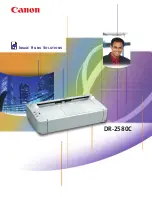
High Speed Color Scanner

KV-S1025CSERIES
KV-S1020CSERIES

Summary of Contents for KV-S1025C SERIES

Page 1: ...sonic Communications Co Ltd All rights reserved Unauthorized copying and distribu tion is a violation of law Order Number KM70603158CE Category Number H19 High Speed Color Scanner KV S1025CSERIES KV S1020CSERIES ...

Page 2: ...ement 60 9 SERVICE UTILITY SELF TEST 63 9 1 Main Menu Indication for Service Utility 63 9 2 Service Utility Function 64 9 3 Operation 65 9 4 Scanner Self test 73 10 TROUBLESHOOTING 75 10 1 Troubleshooting 1 with no error message on the PC 75 10 2 Troubleshooting 2 According to an error message on the PC 80 11 CIRCUIT DIAGRAM 87 11 1 Block Diagram 1 Image Processing 87 11 2 Block Diagram 2 Boards 8...

Page 3: ...ss which is made from Tin Sn Silver Ag and Copper Cu This model and others like it manufactured using lead free solder will have PbF stamped on the PCB For service and repair work we suggest using the same type of solder Distinction of PbF PCB PCBs manufactured using lead free solder will have a PbF stamp on the PCB Caution PbF solder has a melting point that is 50 70 F 30 40 C higher than Pb sold...

Page 4: ...s lead mercury cadmium hexavalent chro mium polybrominated biphenyls and polybrominated diphenyl ethers have been either totally eliminated or limited to the concen tration level below maximum allowed Consequently spare parts have been changed to RoHS compliant parts where applicable Due to spare parts application of RoHS legislation non compliant spare parts cannot be used to repair compliant pro...

Page 5: ...eed tray capacity 50 sheets 80 g m2 20 lb New paper Exit Tray capacity 50 sheets 80 g m2 20 lb New paper Unit External dimensions Width x Height x Depth 317 x 196 x 218 mm 12 5 x 7 8 x 8 6 in When closing the Exit Tray with Stand and no Feed Tray Weight 4 2 kg 9 3 lb Power requirement 2AC 100 120 V 50 60 Hz to AC Adaptor 3 AC 220 240 V 50 60 Hz to AC Adaptor Power consumption Maximum Scanning mode...

Page 6: ... Russia 859 xxxx xxxx 5 SERIAL No for Korea 860 xxxx xxxx 6 SERIAL No for Australlia 857 xxxx xxxx 7 SERIAL No for China 861 xxxx xxxx 8 SERIAL No for Taiwan 862 xxxx xxxx x Don t care 2 Applied to KV S1025C for USA and other countries where power supply AC100 to 120 V is used 3 Applied to KV S1025C G U R K A CN for German UK Russia Korea Australlia China and other countries where power supply AC2...

Page 7: ...50 sheets 80 g m2 20 lb New paper Exit Tray capacity 50 sheets 80 g m2 20 lb New paper Unit External dimensions Width x Height x Depth 317 x 196 x 218 mm 12 5 x 7 8 x 8 6 in When closing the Exit Tray with Stand and no Feed Tray Weight 4 1 kg 9 1 lb Power requirement 2 AC 100 120 V 50 60 Hz to AC Adaptor 3 AC 220 240 V 50 60 Hz to AC Adaptor Power consumption Maximum Scanning mode 24 W Minimum Idl...

Page 8: ... Russia 868 xxxx xxxx 5 SERIAL No for Korea 869 xxxx xxxx 6 SERIAL No for Australlia 866 xxxx xxxx 7 SERIAL No for China 870 xxxx xxxx 8 SERIAL No for Taiwan 871 xxxx xxxx x Don t care 2 Applied to KV S1020C for USA and other countries where power supply AC100 to 120 V is used 3 Applied to KV S1020C G U R K A CN for German UK Russia Korea Australlia China and other countries where power supply AC2...

Page 9: ...atus LED Scanner Status Remarks Green Red ON OFF Ready Blink Slow OFF Sleep ON Blink Slow Warning For cleaning or replacing roller Blink Slow Blink Slow Warning in Sleep For cleaning or replacing roller ON ON Error Blink Fast OFF Warming Up ...

Page 10: ...10 ...

Page 11: ...11 4 INSTALLATION 4 1 Minimum Space Requirements Be sure to maintain the recommended space requirements for proper ventilation Fig 4 1 1 Dimensions for proper ventilation ...

Page 12: ...talling of each end user the Stand can be released from the scanner by removing the 2 screws 4 2 1 Installing Feed Tray 1 Take out the Feed Tray from the accessory carton box and attach the tray to the scanner in the direction of the arrows 2 Pull out the Feed Tray Extension in the direction of the arrow as required ...

Page 13: ...13 4 2 2 Setting Exit Tray 1 Open the Exit Tray forward 2 And also open the Exit Tray Extension ...

Page 14: ...ss of documents up to 2 mm 0 08 in 20 sheets at 80 g m2 on the Feed Tray 2 Set the card on the Mixed Batch Card Guide in the landscape Note The acceptable card condition on the Mixed Batched Card Guide ISO format card Size 85 6 x 54 0 mm 3 37 x 2 13 in Thickness 0 76 mm 0 03 in Embossed card is also available Set only one card at a time 1 Attach the Mixed Batch Card Guide by inserting its tips int...

Page 15: ...ner to a Personal Computer Note Power Cord shown on the above Figure is for AC100 120 V Caution 1 Be sure to use the AC Adaptor and Power Cord supplied with the scanner unit 2 Use only the USB Cable enclosed in the scanner unit ...

Page 16: ...1 Windows 2000 is Microsoft Windows 2000 operating system 2 Windows XP is Microsoft Windows XP operating system 3 Microsoft and Windows are either registered trademarks or trademarks of Microsoft Corporation in the United States and or other countries 4 Pentium is a trademark or registered trademark of Intel Corporation or its subsidaries in the United States and other countries 5 Each company s n...

Page 17: ... VIEWS 5 1 CCD 5 2 Rollers and Sensors Optical Unit F Optical Unit B Conveyor Motor Conveyor Roller Starting Sensor Exit Roller Free Rollers Double feed Prevention Roller Door Detector Paper Sensor Paper Feed Roller ...

Page 18: ...18 5 3 Boards PANEL Board DOOR DETECTION Board STARTING SENSOR Board CONTROL Board PAPER SENSOR Board ...

Page 19: ...imes as fast as the speed of the Paper Feed position 4 When the leading edge of the document pushes down the Starting Sensor s arm the leading edge is detected and scanning the image will start after a certain interval 5 When the trailing edge of the document passes through the separation section the continuous rotation of the Paper Feed Roller during a series of scanning enables the following doc...

Page 20: ...Feed Tray pushing the arm up away from the sensor 6 2 2 Starting Sensor The Starting Sensor turns ON when the document is fed to the scanning start position pushing the arm down away from the sensor 6 2 3 Door Detector The Door Detector turns OFF when the ADF Door is closed interrupting the detector with the claw ...

Page 21: ...b which can vary greatly between users Therefore the values can also vary Description Part Reference No 2 4 6 8 40 50 60 70 80 90 100 Paper Feed Roller Ref No 85 in Sec 14 1 C C C Clean each part every 2 x 1000 sheets scanning C C C C C R Double feed Prevention Roller Ref No 40 in Sec 14 1 C C C R C C C C R Conveyor Roller Ref No 87 in Sec 14 1 C C C C C C C C C Exit Roller Ref No 96 in Sec 14 1 C...

Page 22: ... Switch off and unplugging the AC Adaptor from the scanner 2 Remove the Feed Tray 3 Push the Door Open Button to open the ADF Door Note If the ADF Door does not open even with the Door Open Button pushed repeatedly there is a possibility that the door is not latched In this case try to close the ADF Door until it clicks into place ...

Page 23: ...pening the bag The Roller Cleaning Paper KV SS03 Option is available via sales route 2 If the ADF Door does not open even with the Door Open Button pushed repeatedly there is a possibility that the door is not latched In this case try to close the ADF Door until it clicks into place Maintenance Parts 1 Action Code Action Comments Paper Feed Roller C Clean each surface with KV SS03 Option Roller Cl...

Page 24: ...ay be hot Be sure to allow the inside of the scanner to cool down before performing any maintenance or coming in contact with the inside of the unit Fig 7 2 2 2 Cleaning Position C Clean the dirt off around each surface with KV SS03 Option Roller Cleaning Paper ...

Page 25: ...ce 2 Install the Feed Tray See 4 2 1 3 Turn on the scanner by plugging the AC Adaptor to the scanner and turning the Power Switch on 4 After cleaning the Paper Feed Roller and Double feed Prevention Roller execute Clear Counter for cleaning roller with Service Utility See 9 3 4 ...

Page 26: ... Roller from the Roller Exchange Kit KV SS030 6 Install the new Paper Feed Roller with its gear facing to the left seen from the back and close the Paper Feed Roller Cover Note Make sure to close the Paper Feed Roller Cover tightly by pressing both ends of the cover 7 Close the ADF Door slowly until it clicks into place See 7 2 3 8 After installing the Feed Tray turn on the scanner by plugging the...

Page 27: ...ntion Roller from the Roller Exchange Kit KV SS030 7 Install the new Double feed Prevention Roller into the metal holder with the longer groove facing to the right side seen form the back and close the Double feed Prevention Roller Cover Note Make sure to close the Double feed Prevention Roller Cover tightly by pressing both ends of the cover 8 Close the ADF Door slowly until it clicks into place ...

Page 28: ...28 ...

Page 29: ...ts item Unit Components item and Circuit Board assemblies item When reassembling perform the steps in the reverse order unless otherwise instructed in the Reassembling Notes Note Disassembly flowchart explanation This sample flowchart shows that to disassemble C procedures 1 and 2 must be performed first before proceeding to procedure 3 ...

Page 30: ...2 Before disassembling any of the above parts except for 8 2 7 and 8 2 8 perform the following steps 1 Unplug AC Adaptor from the scanner See 7 2 1 2 Remove the Feed Tray and Stand See 4 2 3 Remove the Exit Tray extending the tips of the tray on both sides in the direction of the arrows ...

Page 31: ...R by sliding the cover backward in the direction of the arrow 1 and away from the scanner in the direction of the arrow 2 1 Push Door Open Button to open the ADF Door See 8 2 1 1 2 Remove the screw 3 Remove the Side Cover L by sliding the cover backward in the direction of the arrow 1 and away from the scanner in the direction of the arrow 2 ...

Page 32: ...spacer on the Rear Cover 2 Remove the 4 screws on the Bottom Cover 3 Pull out the Bottom Cover in the direction of the arrow 1 Remove the Side Cover R See 8 2 1 2 Remove the Side Cover L See 8 2 2 3 Remove the Bottom Cover See 8 2 3 4 Remove the 2 screws and the Discharged Brush ...

Page 33: ...5 Remove the screw from the right 6 Remove the screw from the left 7 Open the ADF Door 8 Remove the Front Cover in the direction of the arrows 2 while holding up the cover in the direction of the arrows 1 ...

Page 34: ...th spacer 4 While slightly lifting the Rear Cover in the direction of the arrow 1 paying attention to the contact to the side of Power Switch slide the cover out in the direction of the arrow 2 1 Push Door Open Button to open the ADF Door See 8 2 1 1 2 Remove the 2 screws 1 from each side 3 Close the ADF Door slowly until it clicks into place ...

Page 35: ...35 4 Pull and remove the Top Cover while releasing the 3 claws 5 Disconnect the connector to the PANEL Board to release the Top Cover from the scanner ...

Page 36: ...e performing any maintenance or coming in contact with the inside of the unit 1 Slide the Scanning Glass F in the direction of the arrow 1 while pushing both ends of the glass to unlock the glass from the scanner 2 Insert the Glass Picker to the notch of the Scanning Glass F and then hook and lift up the glass upwards to release it from the Chassis ...

Page 37: ...f the arrow 1 seen from the front 2 While facing the glass in the direction of the arrow 2 to determine the glass default position insert the 4 notches to the frame of the chassis in the direction of the arrow 3 3 Slide the Scanning Glass F in the direction of the arrow 4 while pushing both ends of the glass to lock the glass ...

Page 38: ... performing any maintenance or coming in contact with the inside of the unit 1 Slide the Scanning Glass B in the direction of the arrow 1 while pushing both ends of the glass to unlock the glass from the Conveyor 2 Insert the Glass Picker to the notch of the Scanning Glass B and then hook and lift up the glass upwards to release it from the Conveyor ...

Page 39: ...the direction of the arrow 2 to determine the glass default position insert the 4 notches to the frame in the direction of the arrow 3 2 Slide the Scanning Glass B in the direction of the arrow 4 while pushing both ends of the glass to lock the glass ...

Page 40: ... the clamps inside and outside of the Base Plate 4 Remove the 5 screws and the screw with the FG cable 5 Remove the Base Plate paying attention to the contact between the cables and the plate edge 6 Remove the Ground Earth Plate 2 7 Remove the screw a and the Tension plate Assembly with the spring And remove the 2 screws b and the Side plate Assembly ...

Page 41: ...41 8 Remove the screw c and the screw d And pull out the Conveyor Motor ...

Page 42: ... chassis that determine the assembly position And fasten the 2 screws b 2 With one side of the spring hung to the Tension plate Assembly hang the other side of the spring to the hole of the Side plate Assembly 3 Position the Idle pulley of the Tension plate out of the Conveyor Belt See BELT LAYOUT below ...

Page 43: ...w by half rotation 5 Confirm the Tension plate Assembly is slid by the spring in the direction of the arrow 6 Confirm the conveying function by rotating the Conveyor Roller by a few rotations 7 Fasten the screw a while pushing the Tension plate Assembly ...

Page 44: ...ing And remove the 2 screws b and the Side plate Assembly 5 Remove the Conveyor Belt from the Conveyor Roller Reassembling Note Tension plate Assembly See 8 3 1 6 Pull and remove the Pulley of the Conveyor Roller in the direction of the arrow while unlocking the stopper on the pulley Note After reassembling the Pulley be sure to check the Pulley s lock to the Conveyor Roller by pulling the pulley ...

Page 45: ...remove the bearing from the Conveyor Roller in the direction of the arrow 8 After opening the Paper Feed Roller Cover remove the cover while slightly bending it And remove the Paper Feed Roller 9 Remove the Arm Guide ...

Page 46: ... pushing the tip of the hook in the direction of the arrow 0 11 Slide the Conveyor Roller with the Conveyor Roller Bearing in the direction of the arrow 2 and remove it from the notch in the scanner 12 Remove the Support bearing 13 Remove the Conveyor Roller Bearing from the Conveyor Roller while unlocking the poly slider ...

Page 47: ...ssembly 3 Remove the Conveyor Belt from the Exit Roller Reassembling Note Tension plate Assembly including BELT LAYOUT See 8 3 1 4 Pull and remove the Pulley of the Exit Roller in the direction of the arrow while unlocking the stopper on the pulley Reassembling Note After reassembling the Pulley be sure to check the Pulley s lock to the Exit Roller by pulling the pulley ...

Page 48: ...earing in the direction of the arrow 1 while pushing the tip of the hook in the direction of the arrow 0 7 Slide the Exit Roller with the Conveyor Roller Bearing in the direction of the arrow 2 and remove it from the notch in the scanner 8 Remove the Support bearing 9 Remove the Conveyor Roller Bearing from the Exit Roller while unlocking the poly slider ...

Page 49: ... the connector cables from the clamps inside and outside of the Base Plate 4 Remove the 5 screws and the screw with the FG cable 5 Remove the Base Plate paying attention to the contact between the cables and the plate edge 6 Remove the Ground Earth Plate 2 7 Remove the 2 screws and disconnect the 2 connectors ...

Page 50: ...om the clamps inside and outside of the Base Plate 4 Remove the 5 screws and the screw with the FG cable 5 Remove the Base Plate paying attention to the contact between the cables and the plate edge 6 Remove the Ground Earth Plate 2 7 Release the cable from the clamp and disconnect the CCD Board F connector 8 Remove the 2 screws ...

Page 51: ...ll out the Cable 2 in the direction of the arrow 2 so that the Lamp Holder F can be held upwards easily 5 Slide Lamp Holder F slightly in the direction of the arrow 3 and lift the holder 6 Unhook the wires and remove the Lamp F Reassembling Note When attaching the Lamp Holder F to the scanner insert the hooks of the holder to the holes and slide them in the direction of the arrows until they stop ...

Page 52: ...onnect the 2 connectors 4 Remove the Lamp Drive Board B paying attention to the 2 Claws supporting the board 1 Remove the Top Cover See 8 2 6 2 Release 2 clamps securing the wires 3 Disconnect the connector to the CCD Board B 4 Remove the 2 screws 5 While leaning the unit forward in the direction of the arrow 1 pull out the Optical Unit B backward in the direction of the arrow 2 ...

Page 53: ...B See 8 3 8 2 Remove the 2 screws and disconnect the connector from the Lamp Drive Board B And remove Lamp Holder B from the scanner 3 Unhook the wires and remove the Lamp B Reassembling Note Be sure to push the center area on the Lamp Holder B to attach the holder to the scanner ...

Page 54: ...ove the Lamp B See 8 3 9 2 Release the guide of the Conveyor distorting the chassis outside 3 Remove the Conveyor Note When disassembling Free Roller Be sure to remove the Discharged Brush before removing the rollers See 8 2 4 ...

Page 55: ...oard from the Top Cover 1 Remove the Top Cover See 8 2 6 2 While unlocking the 2 claws remove the PAPER SENSOR Board from the scanner 3 Disconnect the connector Note Disassembling Arm for Paper Sensor 1 Open the Double feed Prevention Cover 2 Push out the arm in the direction of the arrow 1 after releasing the tip of the arm from the hook of the cover ...

Page 56: ...e 8 2 6 2 While unlocking the claw remove the DOOR DETECTION Board from the scanner 3 Disconnect the connector Reassembling Note Be sure to support the board with the claw after inserting the tip of the board into the hole to determine the detector position ...

Page 57: ...xing the USB connector 3 Remove the 6 screws on the CONTROL Board 4 Release the wires from the 2 clamps 5 Disconnect the 6 connectors Reassembling Note When reassembling the CONTROL Board attach the screw to the USB connector before fixing the bottom of the board with the 6 screws ...

Page 58: ... See 8 3 6 2 While unlocking the claw remove the STARTING SENSOR Board from the scanner 3 Disconnect the connector Reassembling Note Be sure to support the board with the claw after inserting the tip of the board into the hole to determine the sensor position ...

Page 59: ...r 1 Disassembling 1 Remove the STARTING SENSOR Board See 8 4 5 2 Remove the Conveyor Roller See 8 3 2 3 Rotate the arm in the direction of the arrow 1 and pull up it in the direction of the arrow 2 2 Reassembling Arm with the Spring ...

Page 60: ... b Adjust Back Horizontal Position in Individual Position c Adjust Back Width in Individual Position 1 Lamp F R A 1 Adjust Shading 2 Adjust All Position or the following adjustment should be required a Adjust Front Vertical Position in Individual Position b Adjust Front Horizontal Position in Individual Position c Adjust Front Width in Individual Position 1 Lamp Drive Board F R A 1 Adjust Shading ...

Page 61: ...ill affect the scanning positions A 1 Adjust the following adjustment or adjust All Position a Adjust Front Vertical Position in Individual Position b Adjust Front Horizontal Position in Individual Position c Adjust Back Vertical Position in Individual Position d Adjust Back Horizontal Position in Individual Position 1 Circuit Board or Part Action Code Required Adjustment Remarks ...

Page 62: ...62 ...

Page 63: ...oftware also includes a user utility function Executing ServiceUtility exe will allow you to operate all the functions found in this service utility software Note This Service Utility is not included with the scanner Please call service or technical support to obtain the utility software The software should be used only by an authorized service technician Improper use of this software may cause da...

Page 64: ...on Sleep Mode 1 Used to set this setting to Enable or Disable and to set Waiting Time before entering the Sleep Mode 1 Vertical Line Reduction 1 Used to reduce vertical lines on the scanned image caused by a scratch or dust in the scanning area 4 Warning Setting 1 Used to set the number of document scanning that enables the Service Utility to inform the warning messages roller replacement timing a...

Page 65: ...is open or does not close tightly Or the door detection mechanism does not work properly Fxx System error occurred Please consult with a service representative This type of error code requires a Service person s attention No Paper Please set the paper No paper error The rollers need to be cleaned Please clean the rollers Please select Clear Counter button after cleaning the rollers Warning for cle...

Page 66: ...Classified Code Contents Classified Code Contents Classified Code Contents U1 Document H1 F1 U2 Document H2 F2 Hardware U3 Door H3 F3 U4 H4 F4 U5 H5 F5 Sensor U6 H6 F6 Scanning U7 H7 F7 U8 H8 F8 U9 H9 F9 ST1 Error Contents 0x Communication error 1x Paper jam error 2x Door open error 3x Mechanical function error 4x 5x Scanning error 6x 7x 8x Hardware error 9x Hardware error Ax Bx Cx Dx Ex Fx ...

Page 67: ...4 00 Back side gain error ST4 80 White standard area was not found F63 1 53 00 00 00 Back side black level error Item Operation Default Remarks Update All Counters 1 Click Update All Counters to update counter s values 2 Confirm the values of the System After Clean Roller After Replace Double feed Prevention Roller and After Replace Paper Feed Roller are updated on the main menu Clear Counter Afte...

Page 68: ... area glass reference area according to the message on the display and then click OK 4 Set the 3 sheets of clean white paper size Letter or A4 on the Feed Tray in the portrait orientation and then click OK to start this execution 5 Confirm the result And then click OK 6 Click Close to get back to the main menu Until this process is completed do not stop the process and do not open the ADF door War...

Page 69: ...onveyor Motor on the main menu 2 Click START on Conveyor Motor dialog box to start continuous Conveyor Motor rotation until clicking STOP 3 Click Close to get back to the main menu Feed 1 Set documents on the Feed Tray 2 Click Feed on the main menu 3 After setting each Test Condition click START on Feed dialog box to start feeding documents 4 According to the message on the display finish the test...

Page 70: ...TART on the CCD Level dialog box to start CCD Level Test 5 Check whether the peak level is within the specification See Remarks 6 Click STOP to finish this test 7 Click Close to get back to the main menu 8 Open the ADF Door and then remove the paper Memory 1 Click Memory on the main menu 2 Click START on Memory dialog box to start Memory Read Writer Test 3 Check the result 4 Click Close to get bac...

Page 71: ... And click OK to start the shading correction 4 Confirm the result 5 Click OK to get back to the main menu All Position 1 Set 2 pcs of Test Chart A4 Part No See 14 3 on the Feed Tray in the portrait orientation 2 Click All Position on the main menu to execute the scanning position length width and paper end adjustment 3 Check the result 4 Click OK to get back to the main menu Set 2 pcs of Test Cha...

Page 72: ...just Front V Position 5 Adjust Front H Position 6 Adjust Back Width 7 Adjust Back V Position 8 Adjust Back H Position 1 to 5 Face down the chart on each individual adjustment 6 to 8 Face up the chart on each individual adjustment KV S1025C Series Only 2 Adjust Manually Length Increasing a value allows the scanning image to extend vertically Paper End Position On the LC Length Control mode increasi...

Page 73: ...he scanner 2 Release the button at the time when the LEDs change to the contents in the right column LED Red OFF LED Green ON OFF ON 3 Set documents on the Feed Tray OFF ON 4 Push the START STOP Button once to start the test OFF ON 5 Push the START STOP Button once to stop the test OFF ON 6 Turn off the scanner to finish the test 3 Shading 1 While pushing START STOP Button on the front panel turn ...

Page 74: ...n the front panel turn on the scanner 2 Release the button at the time when the LEDs change to the contents in the right column LED Red ON LED Green ON ON ON 3 Push the START STOP Button once to turn on the Lamp F ON ON 4 Push the START STOP Button once to turn on the Lamp B and to turn off the Lamp F ON ON 5 Push the START STOP Button once to turn on the Lamp F and Lamp B ON ON 6 Push the START S...

Page 75: ...k the soldering condition of the following parts and of their surrounding circuit on the CONTROL Board 1 IC1014 DC DC 2 IC1007 Gate Array especially 229th pin 3 IC1016 CPU especially the 67th and 62nd pins 4 IC1012 Reset IC 4 Check the soldering condition of the following parts on the CONTROL Board 1 Q1010 Q1011 Q1013 Q1014 2 CN1007 5 Monitor the following signals on the CN1007 1 CN1007 3rd pin 8 ...

Page 76: ...ent the scanner needs in Sec 9 3 6 to re adjust the scanning position 2 The Optical Unit is not installed properly 1 Re assemble the Optical Unit See 8 3 The document skews when scanned 1 Document Guides are not set properly according to the size of documents on the Feed Tray 1 Slide and set the Document Guides according to the document size 2 Mixed Batch Card Guide is not set properly 1 Set the g...

Page 77: ...ng condition of the following parts 1 between CN2501 CCD Board B and CN1002 CONTROL Board 2 Check the soldering condition of the following parts and their surrounding circuit on the CCD Board B 1 IC2502 2 IC2503 3 Check the soldering condition of the following parts and their surrounding circuit on the CONTROL Board 1 IC1007 Gate Array especially 73rd 74th 79th and 80th pins 2 IC1004 IC1005 A D Co...

Page 78: ...78 Fig 10 1 1 Fig 10 1 2 Fig 10 1 3 Fig 10 1 4 Fig 10 1 5 Fig 10 1 6 ...

Page 79: ...79 Fig 10 1 7 Fig 10 1 8 ...

Page 80: ... test in Sec 9 3 6 to check the sensor condition 2 Check whether lay out between the arm and Starting Sensor is proper Doesn t the arm deviate from its default position 6 Conveyor Motor or mechanical parts gear and others do not work properly 1 Perform the Conveyor Motor test or Feed test in Sec 9 3 6 to check whether the motor rotation is transmitted to the Paper Feed Roller properly And check th...

Page 81: ...cument 2 Check the arm s swing condition 3 Re position or remove it 3 A Dust exists around Paper Sensor or Starting Sensor to prevent the sensor from working correctly 1 Blow off the dust 2 Perform the Key Sensor test in Sec 9 3 6 U30 Door open 20 00 00 00 1 ADF Door remains open or is not closed properly 1 Close the door surely 2 The claw of the cover is broken not to interrupt the Door Sensor 1 ...

Page 82: ... or not 2 Check whether control signals are supplied to lamp F drive circuit Lamp Drive Board F normally 1 Connection between CN1008 CONTROL Board and Lamp Drive Board F 2 Monitor the following signals executing CCD Level test in Sec 9 3 6 CN1008 6th FLAMP_ON Approx 3 V CN1008 7th 16 V 3 Check the Lamp Drive Board F s soldering condition and the connection to the Lamp F 4 Check whether Lamp F is d...

Page 83: ...ON OFF test in Sec 9 4 to check whether the Lamp B lights or not 2 Check whether control signals are supplied to lamp B drive circuit Lamp Drive Board B normally 1 Connection between CN1007 CONTROL Board and Lamp Drive Board B 2 Monitor the following signals executing CCD Level test in Sec 9 3 6 CN1007 6th FLAMP_ON Approx 3 V CN1008 7th 16 V 3 Check the Lamp Drive Board B s soldering condition and...

Page 84: ...r surrounding circuit on the CCD Board B 3 Check the soldering condition of IC1007 Gate Array especially 73rd 74th 79th and 80th pins and of its surrounding circuit on the CONTROL Board 4 Check the soldering condition of IC1004 IC1005 A D Conv and their surrounding circuit on the CONTROL Board 5 Monitor the following CCD Timing signals on the CN1001 1 BCCD_TG See Fig 10 1 5 2 BCCD_CLK1 See Fig 10 ...

Page 85: ...85 Fig 10 2 5 Fig 10 2 6 Fig 10 2 7 Fig 10 2 8 Fig 10 2 9 ...

Page 86: ...86 ...

Page 87: ...e output from the CCD F and the CCD B 3 The analog signals are respectively converted to digital signals by the AFE IC1004 IC1005 Analog IC that operates as A D converter 4 And the converted digital signals are transmitted to the image processing IC Gate Array IC1007 5 And according to the command from PC the Gate Array IC1007 performs image processing such as binary coded processing pseudo gradat...

Page 88: ...SW CN5002 JK1002 CN1008 CN1007 CN1001 CN1002 CN5001 CN2501 CN1006 USB STARTING SENSOR Board 1 CCD Board B Lamp Drive Board F Lamp F 1 Lamp B 1 Lamp Drive Board B CN5004 CN5003 PAPER SENSOR Board DOOR DETECTION Board DC IN 16 V JK1001 CN2001 CN1005 Power Switch Note 1 For KV S1025C Series Only CONTROL Board ...

Page 89: ...89 11 3 Block Diagram 3 ...

Page 90: ...ulse 16 16 GND Ground Shield CN1002 CONTROL Board CN2501 CCD Board B CN5003 PAPER SENSOR Board CN5004 DOOR DETECTION Board Pin No Signal Name Description CN1002 CN2501 CN5003 CN5004 1 1 12VB 12 V 2 2 GND Ground 3 3 BCCD_R Back CCD Red Data Analog 4 4 GND Ground Shield 5 5 BCCD_G Back CCD Green Data Analog 6 6 GND Ground Shield 7 7 BCCD_B Back CCD Blue Data Analog 8 8 GND Ground Shield 9 9 BCCD_TG ...

Page 91: ...D_G Green LED signal 4 4 LED_R Red LED signal 5 1 GND GND 6 2 BLAMP Back Lamp ON 7 3 16V 16 V CN1008 CONTROL Board CN5002 STARTING SENSOR Board Lamp Drive Board F Pin No Signal Name Description CN1008 CN5002 Lamp Drive Board F 1 1 GND Ground 2 2 STARTING Starting signal 3 3 3 3V 3 3 V 4 N C Not used 5 1 GND GND 6 2 FLAMP Front Lamp ON 7 3 16V 16 V JK1001 CONTROL Board USB Interface Pin No Signal N...

Page 92: ...V_ON DC ON OFF Signal Lamp Drive Board F Lamp Connector Pin No Signal Name Description Lamp Drive Board F Lamp Connector 1 1 H V High Voltage 550 V AC 2 2 GND Ground Lamp Drive Board B Lamp Connector Pin No Signal Name Description Lamp Drive Board B Lamp Connector 1 1 H V High Voltage 550 V AC 2 2 GND Ground ...

Page 93: ...93 12 SCHEMATIC DIAGRAM Index 12 1 CONTROL Board 12 2 PANEL and SENSOR Boards 12 3 CCD Board F 12 4 CCD Board B ...

Page 94: ...29 L1032 BLM18AG601SN1D L1033 L1036 BLM18AG601SN1D R1198 R1199 R1200 R1201 R1202 R1203 5 1 CONTROL Board KV S1025C Series KV S1020C Series KV S1025C Series Only KV S1025C Series Only KV S1025C Series Only KV S1025C Series Only ...

Page 95: ...95 5 2 CONTROL Board KV S1025C Series KV S1020C Series ...

Page 96: ...96 5 3 CONTROL Board KV S1025C Series KV S1020C Series ...

Page 97: ...97 5 4 CONTROL Board KV S1025C Series KV S1020C Series ...

Page 98: ...98 R1204 R1205 R1206 R1207 R1208 R1209 R1210 R1211 R1212 R1213 R1214 R1215 R1216 R1217 5 5 CONTROL Board KV S1025C Series KV S1020C Series KV S1025C Series Only not mounted not mounted ...

Page 99: ... R5013 R5007 R5008 R5009 R5010 R5014 R5015 R5016 R5017 R5018 R5019 1 1 PANEL PAPER SENSOR STARTING SENSOR and DOOR DETECTION Boards KV S1025C Series KV S1020C Series PANEL Board STARTING SENSOR Board DOOR DETECTION Board PAPER SENSOR Board 0150 ...

Page 100: ...oard F BLM18AG601SN1D BLM18AG601SN1D BLM18AG601SN1D BLM18AG601SN1D R2041 R2042 R2043 100 470 33 33 33 33 470 470 L2013 L2016 BLM18BA470SN1D L2017 L2018 BLM18AG121SN1D 1 1 CCD Board F KV S1025C Series KV S1020C Series ...

Page 101: ...12 4 CCD Board B R2541 R2542 R2543 BLM18AG601SN1D BLM18AG601SN1D BLM18AG601SN1D BLM18AG601SN1D 470 33 33 33 33 470 470 L2513 L2516 BLM18BA470SN1D L2517 L2518 BLM18AG121SN1D 1 1 CCD Board B KV S1025C Series ...

Page 102: ...102 ...

Page 103: ...103 13 CIRCUIT BOARDS Index 13 1 CONTROL Board 13 2 PANEL Board 13 3 PAPER SENSOR Board 13 4 STARTING SENSOR Board 13 5 DOOR DETECTION Board 13 6 CCD Board F 13 7 CCD Board B KV S1025C Series Only ...

Page 104: ...104 13 1 CONTROL Board 13 1 1 Front Side PbF stamp ...

Page 105: ...105 13 1 2 Back Side ...

Page 106: ...106 13 2 PANEL Board 13 3 PAPER SENSOR Board 13 3 1 Front Side 13 3 2 Back Side ZC R5010 R5009 R5008 R5007 Panel Board PbF stamp ZC R5015 R5016 R5014 Paper Sensor Board PbF stamp ...

Page 107: ... 4 STARTING SENSOR Board 13 4 1 Front Side 13 4 2 Back Side 13 5 DOOR DETECTION Board 13 5 1 Front Side 13 5 2 Back Side Starting Sensor Board zc PbF stamp Door Detection Board zc R5017 R5018 R5019 PbF stamp ...

Page 108: ...108 13 6 CCD Board F 13 6 1 Front Side 13 6 2 Back Side 13 7 CCD Board B KV S1025C Series Only 13 7 1 Front Side 13 7 2 Back Side PbF stamp PbF stamp ...

Page 109: ...109 14 Parts Location and Mechanical Parts List ...

Page 110: ...110 14 1 Exterior and Chassis ...

Page 111: ...r F ISO PC 56 PPB853CHS01A CONTROL Board RTL PbF 57 PJWS8530M Switch 58 LAMS 05 Clamper 59 PJUJC0031Z Base Plate 60 PJMZC0005Z Dust Resistant Sheet 61 EDS 1208UV0 Edge Saddle ISO PA 62 PJMYC0021Z Motor Heat Sink 63 PJMYC0022Z Thermal Conductive Rubber 64 PJMEC0065Z Earth Plate 2 65 L6HBYYYC0001 Stepping Motor 66 PJMMC0001Z Motor Bracket 67 PJULC0051Z Tension Plate Assy 68 PJDKC0002Z Idle Pulley 69...

Page 112: ...4 K2CT3DA00004 Power Cord for KV S1025C U KV S1020C U A4 K2CJ2DA00011 Power Cord for KV S1025C A KV S1020C A A4 K2CR2DA00004 Power Cord for KV S1025C G R K KV S1020C G R K A4 K2CA2DA00030 Power Cord for KV S1025C CN KV S1020C CN A5 K1HY04YY0003 USB Cable A6 PJPNC0124Z Cushion R A7 N0JZJJ000002 AC Adaptor A8 PJPFC0047Z Cover A9 PJPNC0125Z Cushion L A10 PJQMC0634Z Installation Manual Ref No Part No ...

Page 113: ... EXBV8V820JV Resistor Array R1074 EXBV8V820JV Resistor Array R1075 ERJ3GEYJ101 100 J 1 10W R1076 ERJ3GEYJ101 100 J 1 10W R1077 ERJ3GEYJ101 100 J 1 10W R1078 ERJ3GEYJ101 100 J 1 10W R1079 EXBV8V470JV Resistor Array R1080 ERJ3GEYJ470 47 J 1 10W R1081 ERJ3GEYJ470 47 J 1 10W R1082 ERJ3GEYJ470 47 J 1 10W R1083 ERJ3GEYJ470 47 J 1 10W R1084 ERJ3GEYJ470 47 J 1 10W R1085 ERJ3GEYJ470 47 J 1 10W R1086 EXBV8V...

Page 114: ...F2G1C1010014 100 M 16V C1009 ECJ1VB1C105K 1 K 16V C1010 ECJ1VB1C105K 1 K 16V C1011 ECJ1VF1H104Z 0 1 Z 50V Ref No Part No Part Name Description Remarks C1012 ECJ1VF1H104Z 0 1 Z 50V C1013 ECJ1VC1H470J 47P J 50V C1014 ECJ1VC1H470J 47P J 50V C1015 ECJ1VC1H470J 47P J 50V C1016 ECJ1VC1H470J 47P J 50V C1017 ECJ1VC1H470J 47P J 50V C1018 ECJ1VC1H470J 47P J 50V C1019 ECJ1VC1H470J 47P J 50V C1020 ECJ1VF1H104...

Page 115: ... C1158 ECJ1VC1H101J 100P J 50V C1159 ECJ1VF1H104Z 0 1 Z 50V Ref No Part No Part Name Description Remarks C1160 ECJ1VF1H104Z 0 1 Z 50V C1161 ECJ1VC1H101J 100P J 50V C1162 ECJ1VC1H101J 100P J 50V C1163 ECJ1VF1H104Z 0 1 Z 50V C1164 ECJ1VC1H101J 100P J 50V C1165 ECJ1VF1H104Z 0 1 Z 50V C1166 ECJ1VC1H101J 100P J 50V C1167 ECJ1VF1H104Z 0 1 Z 50V C1168 ECJ1VF1H104Z 0 1 Z 50V C1169 ECJ1VC1H101J 100P J 50V ...

Page 116: ...Part Name Description Remarks C1724 F1J1A106A024 106P K 10V C1725 F1J1A106A024 106P K 10V C1726 F1J1A106A024 106P K 10V C1727 F1J1A106A024 106P K 10V C1728 F1J1A106A024 106P K 10V C1729 F1J1A106A024 106P K 10V C1730 F1J1A106A024 106P K 10V C1731 ECJ1VF1H104Z 0 1 Z 50V D1001 B0JCME000041 Diode D1002 B0JCME000041 Diode D1003 B0JCME000041 Diode D1004 MA3S132A0L Diode D1005 B0BC017A0028 Diode D1006 MA...

Page 117: ...nector JK1002 K2EE2B000003 DC Jack X1001 H1Z1006B0006 Crystal Resonator X1002 H0J200200002 Oscillator X1003 H0J240500020 Crystal Resonator F1001 K5H402A00010 Fuse Ref No Part No Part Name Description Remarks R5001 ERJ3GEYJ221 220 J 1 10W R5003 ERJ3GEYJ821 820 J 1 10W R5004 ERJ3GEYJ821 820 J 1 10W R5007 ERJ3GEY0R00 0 ohm Jumper R5008 ERJ3GEY0R00 0 ohm Jumper R5009 ERJ3GEY0R00 0 ohm Jumper R5010 ERJ...

Reviews: