background image

7

General


G

ene

ra

l

The unit is a solid CCD camera recorder integrating 2/3-inch 2.2-megapixel components that support interlaced/progressive 
drive (reading all pixels) and record/playback that supports the compression format for AVC-Intra100, AVC-Intra50 and 
DVCPRO HD, DVCPRO50, DVCPRO and DV.
The unit supports the HD and SD methods shown in the following table. The unit is also equipped with CAC (chromatic 
aberration correction function for the magnification ratio chromatic aberration of lenses), Scan Reverse (corrects images when 
Anamo lenses or lenses for film applications are used), and the film-like gamma function.
For recording, the compression and recording methods are selectable among AVC-Intrra100, AVC-Intra50, DVCPRO HD, 
DVCPRO50, DVCPRO and DV. Since minimal image deterioration occurs when recording with AVC-Intra 100 compression in 
particular, high image quality can be retained.
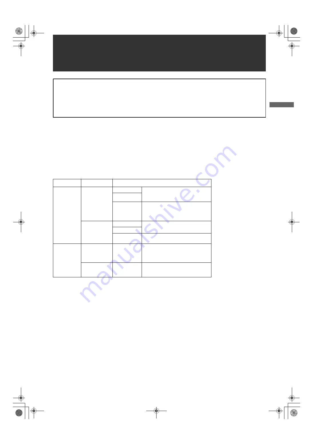
_

Supported formats

Attention

Adjust the following three settings when using the unit for the first time.

z

Adjust the black-balance setting when using the unit for the first time. (Refer to page 50)

z

The unit is delivered from the factory with the color TV standard not yet specified. To revise the settings for frame
frequency according to the TV standard, refer to the procedures described on page 13.

z

Set VF TYPE on the <SYSTEM MODE> screen on the SYSTEM SETTING page depending on your viewfinder. The
factory setting is set to the HD viewfinder.

Mode

SYSTEM MODE

Shooting/Recording method

HD

1080-59.94i

AVC-Intra100

59.94i
29.97P (Native)
23.98P (Native)

AVC-Intra50

DVCPRO HD

59.94i
29.97P Over 59.94i
23.98P Over 59.94i (2-3 Pull down)
23.98PA Over 59.94i (2-3-3-2 Pull down)

1080-50i

AVC-Intra100

50i
25P (Native)

AVC-Intra50

DVCPRO HD

50i
25P over 50i

SD

480-59.94i

DVCPRO50
DVCPRO
DV

59.94i
29.97P Over 59.94i
23.98P Over 59.94i (2-3 Pull down)
23.98PA Over 59.94i (2-3-3-2 Pull down)

576-50i

DVCPRO50
DVCPRO
DV

50i
25P Over 50i

General

AJ-HPX3000G(VQT1K82-5)E.book  7 ページ  2009年11月12日 木曜日 午後8時19分

Summary of Contents for HPX3000

Page 1: ..._Supported formats Attention Adjust the following three settings when using the unit for the first time z Adjust the black balance setting when using the unit for the first time Refer to page 50 z The unit is delivered from the factory with the color TV standard not yet specified To revise the settings for frame frequency according to the TV standard refer to the procedures described on page 13 z ...

Page 2: ...is possible to reproduce images that are more finely detailed _Storage type high sensitivity function DS GAIN The unit uses the storage type gain increase function by driving the CCD progressively With this function it is possible to obtain brighter pictures without increasing noise under low light conditions This is a function that makes it possible to achieve higher sensitivity of up to 20 dB ab...

Page 3: ...st due to overwriting unless the files are deleted or the cards are initialised Recordings are written only to free space _HD Format AVC I100 AVC I50 DVCPRO HD SD Format DVCPRO50 DVCPRO DV Recorded video is compressed through a component digital recording method that uses a state of the art compression technology and sound is recorded using the non compression PCM recording method which excels in ...

Page 4: ...information on clips Regarding SD memory cards please also see Cautions in using SD memory cards page 22 _Recording Time Operation of the following P2 cards with AJ HPX3000 has been verified z AJ P2C004HG 4 GB z AJ P2C008HG 8 GB z AJ P2C016RG 16 GB z AJ P2C032RG 32 GB The model numbers and capacities are accurate as of October 2008 but may change to expand capacity The AJ P2C002SG 2 GB is disabled...

Page 5: ...optimum for confirming shot images on the SD monitor Refer to page 46 _HD SD SDI input function when the AJ YA350AG is attached The camera recorder with the AJ YA350AG extension board attached can record SDI signals input through the SDI input connector only if the signals are in the same format as the camera recorder The unit does not support the various Native methods _Remote control connector B...

Page 6: ...o page 28 While the AJ VF20WBP 59 94 Hz E 50 Hz can also be connected you cannot view video in formats with different frequencies _User button On the side panel of the unit three user buttons USER MAIN USER1 USER2 are available Each button can be assigned the on off function for any frequently used feature selected from among the many features of the unit such as P2 card slot select Refer to page ...

Page 7: ...cuted even if NTSC NTSC J or PAL is selected in the AREA SELECT z When AREA SELECT is revised the _ AREA SET blinks z When these items are set when the unit is used for the first time only the following 8 items are revised When the other settings of the unit are set in MAIN MENU the MENU setting values for items other than the following 8 are ones that were set at the factory 1 SET UP of the DOWN ...

Page 8: ...e DIONIC90 160 HYTRON50 100 140 PROPAC14 TRIMPAC14 NP L7 ENDURA7 10 BP GL65 95 HD SD SDI input board AJ YA350AG GPS unit AJ GPS910G Remote control unit AJ RC10G Video encoder card AJ YAX800G Microphone holder AJ MH800G Memory Card Camera Recorder AJ HPX3000G Tripod adapter SHAN TM700 Stereo microphone AJ MC900G Note All of the devices and accessories other than the unit which are shown in this sys...

Page 9: ...popped up EJECT button to lock in the P2 card 5 Insert a P2 card into camera recorder The P2 CARD ACCESS LED for the appropriate slot indicates the status of the P2 card For how the P2 card status is indicated see P2 CARD ACCESS LED and status of P2 cards page 31 6 Close the slide out door Note Do not leave the slide out door open when moving camera recorder Inserting P2 Cards POWER ON Slide lock ...

Page 10: ... recording to the second one when data are recorded on multiple cards spanning from one to the other hot swap recording For Your Information The P2 CARD ACCESS LEDs may be set to stay off using the menu option ACCESS LED This option can be found on the OPTION MODE screen which is accessible from the SYSTEM SETTING page To prevent the content of a P2 card being accidentally erased position the writ...

Page 11: ...s eww pavc panasonic co jp pro av z When using regular IT tools such as Microsoft Windows Explorer or Apple Finder to transfer data to a PC follow the instructions below However be sure to use the P2 Viewer when returning data to a P2 card Transfer the corresponding CONTENTS folder and LASTCLIP TXT file together as a set Do not transfer individual files from the CONTENTS folder When copying copy t...

Page 12: ...down will be the target card Note When SLOT1 is selected for the menu option P ON REC SLOT SEL recording starts from the P2 card inserted in the smallest slot number after the power is turned on This option is found in the REC FUNCTION screen on the SYSTEM SETTING page When a battery and P2 cards are installed set the switches as detailed below before starting to use your unit Setting the switches...

Page 13: ... the AUTO W B BAL switch toward AWB to adjust the white balance again For directions on making adjustments see Adjusting the White Balance page 47 and Adjusting the Black Balance page 50 3 Point the camera at your subject to adjust the focus and zoom 4 To use the electronic shutter set the shutter speed and operation mode For more information see Setting the Electronic Shutter page 51 5 Press eith...

Page 14: ...e for outputting camera images and playback images is 59 94i or 50i that are pulled down Example of 1080 24PN Native Notes z The recording will start from the top frame of a five frame cycle for 24P 24PA recording or a four frame cycle for 24P native recording respectively Therefore the time code may be discontinued when recording clips continuously in different modes during the recording cycle z ...

Page 15: ... is set to OFF For details of the P REC display refer to 29 INTERVAL REC PRE RECORDING information display page 76 in Viewfinder Status Indication Layout In addition this display can be turned off by configuring the P REC i REC settings The P REC i REC items can be selected from the VF INDICATOR3 screen on the VF page z Immediately after the power is turned on the menu option PRE REC TIME is selec...

Page 16: ...ing the menu option LOOP REC MODE to OFF It is possible to record in intervals of one frame as the shortest length by using the internal memory of the unit To use this option open the REC FUNCTION screen from the SYSTEM SETTING page and set the interval recording mode REC TIME PAUSE TIME and TAKE TOTAL TIME for the menu option INTERVAL REC MODE When the settings are finalized TOTAL REC TIME needed...

Page 17: ...ng and recording according to Basic Procedures lock the camera securely 2 Press either the REC START STOP button REC button on the handle or VTR button at the lens The AJ HPX3000 automatically goes into ONE SHOT pause mode after the specified REC TIME 3 Performs recording for the duration specified under the REC TIME option by pressing either the REC START STOP button REC button on the handle or V...

Page 18: ...ing INTERVAL REC mode operation the P2 card access LED for the inserted P2 card blinks in orange Do not remove the P2 card during this status If you should remove the card accidentally restore clips However even if the clips are restored the last 3 to 4 seconds up to a maximum of about 10 seconds of the recording may be lost if the P2 card is removed while recording onto multiple P2 cards For more...

Page 19: ... with the previous recording is removed When the P2 card is formatted or the clip is deleted when the previous combined clip does not exist z The clip does not stop combining even when the STOP button is pressed in the Menu or on the thumbnail display Set the ONE CLIP REC MODE item to OFF in the Menu A text memo can be automatically added to the start of the recording the start of a section can be...

Page 20: ... as follows when combining to the clip Press and hold the STOP button for about 2 seconds to stop combining to the clip when switching to this mode The following menu items cannot be changed SYSTEM MODE REC SIGNAL CAMERA MODE REC MODE PC MODE 25M REC CH SEL The following Menu items related to the reading writing of the SD memory card and reading of the settings file cannot be executed SD CARD READ...

Page 21: ... PAUSE button plays back the last recorded clip from the beginning After completion of playback the camera recorder enters the stopped state Notes z Set the menu option RET SW found on the SW MODE for CAM OPERATION to R REVIEW z When the OUTPUT SEL switch on the side panel is positioned at MEM the video for REC REVIEW is output from the video output connectors VIDEO OUT and MON OUT connectors and ...

Page 22: ...ill be displayed z If a P2 card is inserted while another P2 card is being played back the clips on the inserted P2 card will not be played back A P2 card inserted during playback will be recognised after playback ends z If you perform variable speed playback on a clip split across more than one P2 card sound may disappear for a moment This is not a fault Text memos are time coded thumbnails added...

Page 23: ... refer to Notes on page 10 a shot mark is added to the top clip only AJ HPX3000 recording mode works according to the priorities outlined in the following table relative to the setting of the menus and switches Disabled for color bars Shot Mark Function Adding Shot Marks SHOT MARK button Recording Setting and Operation Mode Functional operation mode Menu switches related to system recording Button...

Page 24: ... the signals from GENLOCK IN are non standard signals z When SDI is selected the time code or UMID superimposed on SDI input signals are not recorded CAMERA MODE menu option Used to select a camera operation mode when the option REC SIGNAL is set to CAM For information about the behavior for each setting see Recording formats and output connector signal formats page 46 Note When the camera has bee...

Page 25: ...DEO OUT HD SDI 2 and SDI OUT connectors VIDEO OUT SD SDI 3 and SDI OUT connector VIDEOOUT VBS MONOUT and REMOTE connectors When VF connector is set to HD VF When VF connector is set to SD VF Video Sound Video Sound Video Sound Video 1080 59 94i DVCPRO HD CAM 60i 60i 60i 1080i 4ch 1080i 4ch 525i 4ch 525i 1080i 525i 30P 30P Over 60i 30P Over 60i 24P 24PA 24P Over 60i 24PA Over 60i 24P Over 60i 24PA ...

Page 26: ...s on when the SAVE switch is positioned at ON and the output of video and audio is power saved When the menu option SAVE LED is set to P2 CARD The lamp starts blinking when the P2 card remaining free space is getting low The menu option SAVE LED can be found in the VF INDICATOR3 which is accessible from the VF page 5 50 50 Mbps recording playback Lamp In using the SD viewfinder This lamp stays ill...

Page 27: ...llowing pages Selecting Viewfinder Display Information VF INDICATOR1 EXTENDER ON SHUTTER ON FILTER ON WHITE ON GAIN ON IRIS S IRIS CAMERA ID BAR ID POSITION UPPER L DATE TIME OFF ZOOM LVL ON COLOR TEMP ON SYSTEM MODE ON CAMERA MODE ON VF INDICATOR2 CAC OFF FILM REC MODE OFF VF INDICATOR3 P2CARD REMAIN ON BATTERY ON AUDIO LVL ON TC ON COLOR BAR OFF TC OFF SYSTEM INFO NORMAL SAVE LED SAVE REC STATUS...

Page 28: ...ption P2 CARD REMAIN is set to ONE CARD the number of the P2 card slot that contains the target card is indicated together with the remaining space For more information see P2 Card Remaining Free Space capacity Indication page 77 6 P2 card remaining free space MODE CHECK min The number of the P2 card slot that contains the target card and the remaining free space when MODE CHECK is being performed...

Page 29: ...ards loaded in P2 Card Slots 1 5 Remaining free space capacity of each card The numbers denote the P2 card slot numbers The card status is indicated as ACTIVE ACCESSING INFO READING FULL PROTECTED NOT SUPPORTED FORMAT ERROR NO CARD PROXY For details of statuses see P2 CARD ACCESS LED and status of P2 cards page 31 Indicates optional slot status The card status is indicated as PROXY NO CARD NOT SUP...

Page 30: ...to DRS and the AUTO KNEE switch is turned ON OFF Gain has been switched with the GAIN selector switch or a user button When the shutter speed has been switched the shutter speed is indicated Shutter speed is in SYNCRO SCAN mode This appears when the CC filter setting has been selected This appears when the ND filter setting has been selected Lens extender has been turned on or off Indicated when t...

Page 31: ...s Indicates that the camera recorder is set to the USB HOST mode When the external hard disk is not successfully recognized then the indication blinks Thumbnail is being manipulated Displayed when the connection of the DVCPRO connector is abnormal Displayed when proxy recording on either the P2 card or the SD memory card starts when AJ YAX800G is attached the PROXY REC item on the VF INDICATOR3 sc...

Page 32: ...he iris value When the iris is being overridden they blink 28 Zoom indication Z00 Z99 Zoom degree is indicated This indication is not provided for a lens that does not return the zoom position even if the indication is set to ON 29 INTERVAL REC PRE RECORDING information display blink blink h m s P REC blink P REC lit 1 CLIP 1 CLIP START 1 CLIP END 1 CLIP h m END Displayed before and after operatio...

Page 33: ... the P2 card slots is indicated in minutes Example 30min Not provided ONE CARD The number of the P2 card slot holding the target P2 card together with that card s remaining free space indicated in minutes Example 8min Not provided OFF Not provided Not provided LOOP REC mode TOTAL ONE CARD Indicated as LOOP Not provided OFF Not provided Not provided During MODE CHECK Other than LOOP REC mode TOTAL ...

Page 34: ...ce 6 P2 card remaining free space MODE CHECK 7 Camera recorder REC indication 8 Battery type MODE CHECK 9 Battery remaining level voltage 10 MODE CHECK indication area 11 Camera warning and report area 12 User button functions 13 System information and warnings 14 Time code indication 15 Chromatic aberration compensation 16 Extender 17 Color temperature 18 Filter position 19 Dynamic range stretche...

Page 35: ... LVL 35 RC MENU DISP OFF 50M INDICATOR OFF MARKER CHAR LVL 50 SYNCHRO SCAN DISP sec Message appears when Message DISP MODE settings 1 2 3 CC ND filter changed FILTER n n 1 2 3 4 z Gain changed GAIN n dB n 3 0 3 6 9 12 15 18 21 24 27 30 z WHITE BAL switch re positioned WHITE n n A B PRE z OUTPUT AUTO KNEE switch positioned at AUTO KNEE or OFF AUTO KNEE ON or OFF z z Shutter speed mode changed SS 1 ...

Page 36: ...SIG is set to 16 9 as the information of Marker A and 4 3 as the information of Marker B then the 16 9 and 4 3 view angles can easily be checked with the button as required The viewfinder displays the return video signal input to the GENLOCK IN connector while the RET button at the lens is held down To enable this capability select CAM RET for the menu option RET SW This option can be found in the...

Page 37: ... Change the thumbnail image z Format P2 cards and SD memory cards z Uploading and editing clip metadata from the SD memory card Thumbnail screens are configured as follows Thumbnail Manipulations Overview THUMBNAIL OPERATION PROPERTY ALL CLIP SELECTED CLIPS TEXT MEMO CLIPS SLOT CLIPS SETUP EXIT ALL HIDE TEXT MEMO IND DATE FORMAT THUMBNAIL SIZE EXIT DELETE FORMAT REPAIR CLIP EXIT CARD STATUS CLIP P...

Page 38: ...indicated Please refer to Switching the Thumbnail Display page 119 for more information 2 Slot numbers and HDD status This section indicates on which P2 card the pointed clip is recorded The number of the slot that contains the appropriate P2 card is indicated in yellow If the clip is recorded on more than one P2 card then the numbers of all slots that contain the appropriate cards are indicated T...

Page 39: ...refer to Restoring Clips page 123 for more information A clip displayed with a red corrupt marker cannot be restored and must be deleted If the clip cannot be deleted format the P2 card When clips have different formats is displayed instead of 10 Incomplete Clip Indicator Indicates that although a clip is recorded across multiple P2 cards one of these cards is not inserted into a P2 card slot 11 S...

Page 40: ...e thumbnails z Clips with clip numbers displayed in red cannot be played 4 During playback pressing the REW button starts 4a speed reverse playback and the FF button starts 4a speed fast playback Press the PLAY PAUSE button to return to normal playback 5 During clip playback pressing the PLAY PAUSE button will temporarily stop pause the process During a pause pressing the REW button moves the paus...

Page 41: ...at means the image system set in SYSTEM MODE and REC MODE Press the MODE CHECK button to display the viewfinder Refer to 1 System mode page 72 and 3 REC mode page 72 of Viewfinder Status Indication Layout SELECTED CLIPS Display randomly selected clips MARKED CLIPS Display clips with shot marks attached TEXT MEMO CLIPS Display clips with text memo data attached SLOT CLIPS Display clips recorded in ...

Page 42: ...SET Move the pointer to the text memo display on the lower row 4 Select the thumbnail that you intend to replace place the pointer on it and then select OPERATION EXCH THUMBNAIL on the thumbnail menu 5 Press SET When the YES NO confirmation window is displayed select YES by using the cursor button and the SET button The menu closes and the thumbnail for the clip is replaced Notes Display clip prop...

Page 43: ... deleting the shot mark from a clip recorded across multiple P2 cards do this with all these P2 cards inserted into P2 card slots During recording or playback you can add text memos to clips Text memos can be used to play back clips at some point or break clips into chunks and copy the necessary portions Text memos can be added in one of the following ways z Press the TEXT MEMO button during recor...

Page 44: ... STOP button is pressed during playback or the playback has finished at the end of the clip then the thumbnail screen appears again with the pointer replaced with the text memo where the playback started 6 Press the THUMBNAIL MENU button to select EXIT or press the EXIT button to return the pointer to the upper part of the thumbnail screen 1 Select the desired text memo by carrying out steps 1 3 f...

Page 45: ...the SET button to select the clip 3 Press the THUMBNAIL MENU button and select OPERATION DELETE from the thumbnail menu 4 The following screen appears Use the cursor buttons and the SET button to select YES 5 The clip is deleted All selected clips in blue green frames are deleted by this operation Note Pressing the SET button stops the deletion operation in the middle Restores clips that are defec...

Page 46: ...utton and select OPERATION COPY from the thumbnail menu Select Slot 1 5 or SD memory card as the destination 4 The confirmation window appears Use the cursor buttons and SET button to select YES Notes z Do not turn off the power or remove a P2 card while data is being copied Doing so may cause the P2 card to fail If you should accidentally perform one of the above operations defective clips will b...

Page 47: ...RL and install it to your PC https eww pavc panasonic co jp pro av Regarding SD memory cards to be used see Cautions in using SD memory cards page 22 Note The file which was edited by except P2 viewer is displayed as UNKNOWN DATA and may not be read GLOBAL CLIP ID Displays the global clip ID which indicates the shooting status of the clip USER CLIP NAME Displays the clip name specified by the user...

Page 48: ...rder allows you to check the details of read metadata 1 Press the THUMBNAIL button The thumbnail screen appears on the LCD monitor 2 Press the THUMBNAIL MENU button to select METADATA PROPERTY from the thumbnail menu Then the screen like this is displayed 3 Use the cursor buttons to move the pointer Then press the SET button This allows you to view the settings of the read metadata 4 While viewing...

Page 49: ... will be displayed Select META DATA INITIALIZE from the thumbnail menu and press the SET button Select YES when the confirmation screen is displayed Notes z The setting for the displayed language is available only when the area is set to NTSC J For details refer to Color TV Standard Settings Settings for frame frequency page 13 z Japanese or Chinese characters indicated in English or other charact...

Page 50: ...r For the method to confirm the FPGA version of the video encoder card firmware refer to Video Encoder Card Status Display optional page 134 For instructions on updating refer to the P2 support page on the following website https eww pavc panasonic co jp pro av z When PROXY CARD ERROR is indicated in the viewfinder either check the video encoder card or set the unit so that proxy recording is not ...

Page 51: ...e LCD monitor 2 Press the THUMBNAIL MENU button and select OPERATION FORMAT from the thumbnail menu The following screen appears Select SD CARD Select EXIT if formatting is not required 3 The following screen appears Use the cursor buttons and the SET button to select YES 4 The SD memory card is formatted Note SD memory cards can also be formatted from the menu screen For more information see To f...

Page 52: ...nd no indication ON OFF The factory setting is ON indication DATA DISPLAY The time display field of the clip offers a choice of Time Code TC User Bits UB Shooting Time TIME Shooting Date DATE Shooting Time and Date Time DATE or USER CLIP NAME The factory setting is Time Code DATE FORMAT You can specify the display order for the shooting date as either Year Month Day YMD Month Day Year MDY or Day M...

Page 53: ...E The date of the recording TIME The time at the start of the recording DURATION The time length of the clip V FORMAT The recording format for the clip FRAME RATE The frame rate for the playback REC RATE The recording frame rate is displayed This is indicated on the clip that data is recorded in a special way using the camera recorder 5 Clip Meta Data Displays more detailed data about the clip Use...

Page 54: ...lip indicator cannot be modified For the clips recorded on multiple P2 cards modify the metadata while all P2 cards are inserted z Any MEMO with 100 characters or more cannot be modified Select PROPERTY CARD STATUS from the thumbnail menu to set the desired indication mode remaining free space or used memory capacity for the P2 card status display 1 Press the THUMBNAIL button The thumbnail screen ...

Page 55: ... directory structure on the P2 card is not supported The warning can be confirmed on the P2 card detailed information indication in 2 P2 Card Status remaining free space When USED is selected 1 Write protect Mark The mark appears if the P2 card is write protected 2 P2 Card Status used memory capacity The used memory capacity of the P2 card is indicated by a bar graph and a percentage figure The ba...

Page 56: ...x of remaining memory capacity for the Proxy but may differ from the actual remaining capacity For SD or SDHC cards with Class indications the recording time may be reduced significantly compared with the actual capacity when images of short recording time are recorded repeatedly If the remaining memory capacity exceeds 999 min 999 min is displayed The remaining capacity is displayed only when set...

Page 57: ...OUT connector or AUDIO OUT connector differ from the actual input signals Use them for monitoring purposes z The condition indicator character is not shown in the viewfinder screen and the output images z The following functions are not available PRE RECORDING function Loop recording Interval recording function One clip recording function Proxy recording function z When input from the IEEE1394 int...

Page 58: ...ces through the 1394 connection z When connecting the 1394 DV cable see 32 DVCPRO connector page 22 z The AV signals may be disrupted by turning the power of the connected devices ON and OFF or by disconnecting and re connecting the I F cables z It may take several seconds for the system to operate stably when the input signals are switched or operation is transferred from one mode to another Perf...

Page 59: ... z Only one unit at a time must be connected to the PC via USB z The P2 card must not be removed when it is connected via USB z While a USB connection is established the P2 card s access LED should not be lit except when access is being carried out z When a USB device is active recording playback or navigation through clip thumbnails is disabled During a USB connection the USB LED on the side pane...

Page 60: ...onnected the HDD indication in the upper right corner stays illuminated However if this indica tor illuminates red it means that the hard disk drive cannot be copied Confirm the hard disk drive type For information about the HDD indication see Thumbnail Screen page 116 Note In USB HOST mode clips on P2 cards can be displayed but video from the camera or an external device cannot be recorded Clips ...

Page 61: ...on indicates the partition number one P2 card is used as a unit on the hard disc drive Note The screen indicates up to 10 partitions When the number of partitions exceeds 10 scroll down the indi cation with the cursor button to view the hidden partitions Viewing hard disc drive information 5 9 1 2 3 4 6 7 8 11 10 12 Press the set button 1 2 3 4 HDD type Feature Available functions TYPE S A special...

Page 62: ...formation is available Notes z Even for a FAT type hard disc drive the 1001st or later clips are not shown z For a FAT formatted hard disc drive the information about only the first partition is shown z For a P2 STORE AJ PCS060G that has an invalid partition that partition information is shown in gray 12 NAME This section indicates the PARTITION NAME 1 Switch the mode to USB HOST For more informat...

Page 63: ... the hard disc drive You can select clips on the hard disc drive to be written back to P2 cards 1 Switch the mode to USB HOST For more information see Switching to the USB HOST mode page 138 2 Connect a hard disc drive via USB 3 Insert the target P2 card in a slot 4 Press the MENU button and select HDD EXPLORE from the thumbnail menu Move to the appropriate partition and select it with the SET but...

Page 64: ...ficient free space z Do not remove the cable or the target P2 card or turn off the camera recorder or hard disc drive during formatting or copying Doing so requires the camera recorder and the hard disc drive to be reactivated z Since hard disc drives are high precision devices there is a high possibility that they may become incapable of writing data depending on the conditions of use z Take note...

Page 65: ... the setting menu through the SDI IN connector If the formats are different data will not be properly recorded on the P2 card z Note the following points when the REC SIGNAL of the setting menu is set to SDI Audio signals are input from the SDI IN connector Audio signals must be input synchronized with video images Data will be recorded as 48 kHz 4CH 16 bit on a P2 card When the REC SIGNAL item is...

Page 66: ...to and wide angle 2 Set the zoom to manual zoom mode and check the zoom operation Turn the manual zoom lever to check that the image changes to telephoto and wide angle 3 Set the iris to automatic adjustment mode and aim the lens at objects with different degrees of brightness to check that the automatic iris adjustment operates normally 4 Set the iris to manual adjustment mode and turn the iris r...

Page 67: ...nd playback operate properly 2 Inspecting the Audio Level Automatic Adjustment 1 Set the AUDIO SELECT CH1 and CH2 switches to AUTO 2 Set the AUDIO IN CH1 and CH2 switches to FRONT 3 Aim the microphone connected to the MIC IN jack at an appropriate sound source Then check that the level displays for both CH1 and CH2 change according to the sound level 3 Inspecting the Audio Level Manual Adjustment ...

Page 68: ...nd affects the playback sequence etc at the time of thumbnail manipulations z Do not use thinner or other solvents to remove dirt z Wipe the lens with a commercially available lens cleaner z Do not wipe the mirror If dirt or rubbish is sticking on the mirror remove it with a commercially available air blower Smears Smears may appear when shooting an object with very high brightness This phenomenon...

Page 69: ...r K1AA104H0038 Maker part number HA16RX 4P SW1 Hirose Denki PUSH 1 5 2 3 4 Panasonic part number K1AB105B0002 Maker part number NC5FBH NEUTRIK PUSH 1 3 2 Panasonic part number K1AB103A0011 Maker part number HA16PRM 3SG Hirose Denki 5 4 3 2 1 Panasonic part number K1AA105H0016 Maker part number HA16RD 5P 76 Hirose Denki DC OUT 1 GND 2 R TALLY Open collector 3 REC START SW 4 12V OUT Max 1 5 A 1 2 3 ...

Page 70: ...e viewfinder Y signals 8 VF CLK Serial data clock pulse signals 9 VF WR Pulse signals for reading serial parallel conversion data 10 VF DATA Serial data signals for serial parallel conversion 11 UNREG GND GND 12 ZEBRA SW ON OFF of the zebra signals 13 PEAKING Control of the peaking not used 14 SPARE Standby not used 15 VF PR Viewfinder PR signal output 16 VF PB Viewfinder PB signal output 17 MARKE...

Page 71: ... of the built in extender EXTENDER ON GND EXTENDER OFF OPEN 10 ZOOM POSI Zoom position signals 11 FOCUS POSI Focus position signal 12 SPARE Standby not used 1 2 4 5 6 3 7 8 9 10 11 12 Panasonic part number K1AY112JA001 Maker part number HR10A 10R 12SC 71 Hirose Denki START STOP START 5 V 0 V GPS 1 GPS TXA Transmission data from the GPS unit to the camera 2 GPS RXA Transmission data from the camera...

Page 72: ... used 10 SPARE 1 Not used 11 SPARE 2 Not used 12 EXT CLK Not used 13 CLK SHIELD Not used 14 CH 2 SHIELD GND 15 CH 2 HOT Audio input from the wireless receiver CH2 HOT 16 CH 2 COLD Audio input from the wireless receiver CH2 COLD 17 5 6V Power supply to the wireless receiver 18 VIDEO OUT Not used 19 VIDEO RET Not used 20 VIDEO EN Not used 21 RM 1 RM CLK Not used 22 RM 2 RM DATA Not used 23 RM 3 RM W...

Page 73: ...he BATT LED lights up Warning tone Beeps continuously Warning description The battery has run out Recording playback operation The operation stops Countermeasures Replace the battery 2 Card removal error Display window indication Error code E 30 blinks WARNING lamp Blinks 4 times per second Tally lamp Blinks 4 times per second Viewfinder The TURN POWER OFF indicator lights up Warning tone Continue...

Page 74: ...ne Beeps 4 times per second while recording continues Warning description There are abnormal conditions in the image sequence of the 24P 30P or 25P mode Recording playback operation Images can be recorded and played back but some frames may be dropped or the sequences of TC and UB may shift Countermeasures Confirm the recording playback operation after turning OFF the power supply once and then tu...

Page 75: ...om a P2 card Recording playback operation Stop recording or playback After recording is stopped the P2 card where error occurs is write protected Countermeasures Replace the affected P2 card 11 Battery Nearly Empty Display window indication One of the bars in the battery remaining indicator starts blinking WARNING lamp Blinks once per second Tally lamp Blinks once per second Viewfinder The BATT LE...

Page 76: ...1a speed transfer signals in DV format Stops 1394 E 81 Signals being input to the DVCPRO connector are not 1a speed transfer signals in DVCPRO 25 Mbps format Stops 1394 E 82 Signals being input to the DVCPRO connector are not 1a speed transfer signals in DVCPRO50 50 Mbps format Stops The time code section of the display window indicates the appropriate error code that blinks every two seconds 1394...

Page 77: ...t span multiple cannot be reconnected Check selected content INVALID VALUE Entered data was invalid Enter data in a valid range UNKNOWN DATA The metadata character code is invalid Use UTF 8 for the metadata character code Use the viewer to enter correct characters CANNOT REPAIR IN SELECTION Some of the selected clip could not be repaired NO SD CARD No SD card is inserted Insert an SD card NO COPY ...

Page 78: ...urred during hard disk access Check hard disk status and connection CANNOT RECOGNIZE HDD The destination target cannot be properly recognized Reboot the hard disk or connect a different hard disk CANNOT ACCESS CARD An error occurred during P2 card access Check P2 card MISMATCH COMPONENT Copying is not possible since the model number of the destination card does not match that of the source card Us...

Page 79: ...or at least 3 seconds OPTION MENU Displayed when the MENU button is pressed while pressing the LIGHT button Notes z The items highlighted in grey cannot be selected by USER MENU SELECT z The underlined items can only be selected as one whole page with all sub items Individual sub items cannot be selected separately The following letters indicate whether the modified menu data is saved to or read o...

Page 80: ...or Normally this adjustment requires assistance from a video engineer This menu option may be set with an external remote controller and is useful when using the unit without a sound recordist VF Used to select the information items to be displayed in the viewfinder screen CAM OPERATION Used to change settings according to the conditions for the subject MAIN OPERATION Used to specify recording rel...

Page 81: ...ne step A quick turn changes the value rapidly a slow turn makes a fine adjustment To turn an option on or off To select ON turn the JOG dial button clockwise as seen from the front of the camera To select OFF turn the JOG dial button anti clockwise as seen from the front of the camera To return the changed set value to the previous one Press the shot mark menu cancel button to display the message...

Page 82: ... navigate this menu see Setting Menu Options page 159 Note Options with are effective The number of options that can be added to USER MENU is 14 a 3 42 three pages of options for camera related options and 14 one page of options for memory related options Selecting Options for USER MENU USER MENU SELECT SELECT MODE SYSTEM SETTING PAINT VF CAM OPERATION MAIN OPERATION FILE MAINTENANCE AJ HPX3000G V...

Page 83: ...spect ratio 4 3 Record in 4 3 aspect ratio C U F R Items Data Saved Adjustable Range Remarks SCAN REVERSE OFF ON Specify whether image correction is used or not when an anamorphic lens or a lens for film applications is used OFF Images are not corrected ON Images are corrected The vertical and horizontal orientations are inverted C U F R VF TYPE HD SD Specify the type of viewfinder to be attached ...

Page 84: ... SD SDI output C U F SAVE SW AUD OUT ON OFF Select whether or not to forcibly disable the audio output when the SAVE ON OFF switch is set to ON ON Disable audio output OFF Enable audio output C U F SAVE SW LCD ON OFF Select whether or not to automatically turn off the LCD monitor when the SAVE ON OFF switch is set to ON ON Turn off LCD monitor OFF Do not turn off LCD monitor C U F Items Data Saved...

Page 85: ...he recording time recording time needed for the P2 card calculated using REC TIME PAUSE TIME and TAKE TOTAL TIME Note A value based on actual processing is displayed AUDIO REC ON OFF Select whether or not sound will be recorded C U F START DELAY 0SEC 10SEC Set the delay after pressing REC START to start recording in INTERVAL REC C U F PRE REC MODE ON OFF Select whether or not to enable PRE RECORDI...

Page 86: ...perimpose OFF Disable superimpose C U F VF MODE MEM CAM When the REC SIGNAL menu option on the SYSTEM MODE screen is set to CAM select the image to display in the viewfinder MEM Display the playback image in the playback mode CAM Always display the camera image C U F Items Data Saved Adjustable Range Remarks THUMBNAIL OUT ON OFF Select whether or not to output clip thumbnails displayed on the LCD ...

Page 87: ...t 90 lines C U F R H PHASE COARSE 100 000 100 Perform coarse phase adjustment for horizontal hold when configuring a system Items Data Saved Adjustable Range Remarks H PHASE FINE 100 000 100 Perform fine phase adjustment for horizontal hold when configuring a system 1394 SETTING Items Data Saved Adjustable Range Remarks 1394 AUDIO OUT CH1 CH2 CH3 CH4 For selecting the channels for audio signals ou...

Page 88: ...he values set in the items of R GAIN AWB B and B GAIN AWB B OFF The values of the Rch gain and the Bch gain is set to 0 S C U F R RGB BLACK CONTROL Items Data Saved Adjustable Range Remarks MASTER PED 200 015 200 For setting the level of the master pedestal z If the remote control unit is connected settings made from the menu are disabled The set value is displayed S C U F R R PEDESTAL 100 000 100...

Page 89: ... OFF A B For selecting the color correction table when the GAIN switch is in the M position S C U F H MATRIX TABLE OFF A B For selecting the color correction table when the GAIN switch is in the H position S C U F COLOR CORRECTION Items Data Saved Adjustable Range Remarks R SAT 63 00 63 For performing the color saturation correction of red S C U F R R Mg SAT 63 00 63 For performing the color satur...

Page 90: ... 00 63 For performing the hue correction between cyan and green S C U F R G PHASE 63 00 63 For performing the hue correction for green S C U F R G Yl PHASE 63 00 63 For performing the hue correction between green and yellow S C U F R Yl PHASE 63 00 63 For performing the hue correction for yellow S C U F R Yl R PHASE 63 00 63 For performing the hue correction between yellow and red S C U F R COLOR ...

Page 91: ...rd state 1 to 3 The dark portion is extended S C U F MATRIX TABLE OFF A B For selecting the color correction table for the linear matrix S C U F COLOR CORRECT ON OFF For switching ON OFF of the 12 axis independent color correction S C U F HIGH SETTING Items Data Saved Adjustable Range Remarks MASTER GAIN 3dB 12dB 30dB Select the master gain from 3 0 3 6 9 12 15 18 21 24 27 or 30dB S C U F H DTL LE...

Page 92: ...31 Adjust the detail level toward upwards S C U F R DTL GAIN 31 00 31 Adjust the detail level toward the downwards S C U F R DTL CLIP 00 63 For setting the level for clipping the detail signals S C U F R DTL SOURCE R G 2 G B 2 2G R B 4 3G R 4 R G For setting the proportion of the RGB signal components that provide the detail S C U F R MASTER DTL 31 00 31 For revising the master detail level S C U ...

Page 93: ...S C U F R SKIN TONE GET For fetching the color information of A or B which is selected in the SKIN TONE TABLE item near the center marker When this function is executed data from I CENTER to Q PHASE are fetched automatically The fetched data will be the table data of A or B which is selected in the SKIN TONE TABLE item It is impossible to obtain color information of both A and B at the same time S...

Page 94: ...ng is ON S C U F R WHITE CLIP LVL 90 109 Set WHITE CLIP LEVEL S C U F R A KNEE POINT 80 93 107 Set the AUTO KNEE POINT position in 1 steps This setting is enabled when the OUTPUT AUTO KNEE selector switch is set to CAM AUTO KNEE ON S C U F R A KNEE LVL 100 107 109 Set the AUTO KNEE LEVEL S C U F R A KNEE RESPONSE 1 4 8 Set the AUTO KNEE response speed The smaller the setting value the faster the r...

Page 95: ...essed better than when FILM LIKE2 is selected FILM REC The cinema gamma characteristics for film applications are used S C U F R DYNAMIC LVL 200 300 400 500 This is enabled when FILM REC is selected in GAMMA MODE SEL Set the dynamic range S C U F R BLACK STR LVL 00 30 This is enabled when FILM REC is selected in GAMMA MODE SEL Set the BLACK STRECH position S C U F R SD HD FILMLIKE1 FILMLIKE2 FILML...

Page 96: ...n the detail is the same as that for the main line C U F R ZEBRA1 DETECT 0 70 109 Set the ZEBRA1 detection level IRE value C U F R ZEBRA2 DETECT 0 85 109 Set the ZEBRA2 detection level IRE value C U F R ZEBRA2 ON SPOT OFF Set the ZEBRA2 to ON OFF or SPOT C U F R LOW LIGHT LVL OFF 10 15 20 25 30 35 Set the camera incoming light volume at which to display LOW LIGHT C U F R RC MENU DISP ON OFF For th...

Page 97: ...r the safety zone marker OFF Do not display frame 1 Box 2 Corner frame C U F R SAFETY AREA 80 90 100 For setting the size of the safety zone marker It is possible to set the size by units of 1 with a fixed ratio between of width and height C U F R FRAME MARK ON OFF Set the frame marker to ON or OFF C U F R FRAME SIG 4 3 13 9 14 9 VISTA Set the frame marker Only enabled when REC MODE is set to 16 9...

Page 98: ...ERA MODE display C U F R VF INDICATOR2 Items Data Saved Adjustable Range Remarks CAC ON OFF For selecting ON or OFF for the color astigmatism correction display C U F R FILM REC MODE ON OFF For selecting whether to indicate that the Gamma Select is set to the FILM REC mode C U F R VF INDICATOR3 Items Data Saved Adjustable Range Remarks P2CARD REMAIN OFF ONE CARD TOTAL Select the indication mode fo...

Page 99: ...hen the MODE CHECK button is pressed C U F R AUDIO ON OFF For the setting to display the AUDIO screen when the MODE CHECK button is pressed C U F R CAC ON OFF The setting to display the CAC screen when the MODE CHECK button is pressed C U F R Items Data Saved Adjustable Range Remarks P ON IND ON OFF For the setting to display the status screen immediately after turning on the power of the unit Not...

Page 100: ...d set by POSITION1 SELECT in the SHUTTER SELECT screen as the shutter speed selectable by the shutter switch C U F POSITION2 ON OFF Allocate the shutter speed set by POSITION2 SELECT in the SHUTTER SELECT screen as the shutter speed selectable by the shutter switch C U F POSITION3 ON OFF Allocate the shutter speed set by POSITION3 SELECT in the SHUTTER SELECT screen as the shutter speed selectable...

Page 101: ... 50Hz C U F POSITION3 SEL 1 100 1 120 1 250 1 500 1 1000 1 2000 HALF 180 0deg 172 8deg 144 0deg 120 0deg 90 0deg 45 0deg For setting the shutter speed for POSITION 3 1 100 59 94 Hz 1 60 50Hz C U F POSITION4 SEL 1 100 1 120 1 250 1 500 1 1000 1 2000 HALF 180 0deg 172 8deg 144 0deg 120 0deg 90 0deg 45 0deg For setting the shutter speed for POSITION 4 1 100 59 94 Hz 1 60 50Hz C U F Items Data Saved A...

Page 102: ...ossible to confirm the return video signals HD analog HD Y signals SD VBS signals supplied to the GENKLOCK IN connector on the unit by using the viewfinder Notes z When video signals in a format different from that for the video mode of the camera recorder return video is not properly displayed z When the GENLOCK item the GENLOCK screen on the SYSTEM SETTING page is set to INT the return video ima...

Page 103: ...the screen is detected 90 An area equivalent to 90 of the screen is detected C U F R TEMP PRE SEL SW VAR 3 2K 5 6K For selecting whether the PRESET color temperature is variable or switchable between 3200K and 5600K Immediately after revising the value the color temperature for PRESET is set to 3200K For Filter A VAR Selectable within the range from 2300K to 8000K 3 2K 5 6K Switchable between 3200...

Page 104: ...ue for auto iris C U F R A IRIS PEAK AVE 000 030 100 Determine the peak to standard ratio for the auto iris A larger value sets the auto iris to respond to the peak in the IRIS detection window while a smaller value sets it to respond to the average value in the window C U F R A IRIS WINDOW NORM1 NORM2 CENTR Select the auto iris detection window NORM1 The window closer to the center of the screen ...

Page 105: ...nd BATTERY SETTING2 page 185 menus Analog voltage is displayed on the viewfinder screen When BP GL65 or BP GL95 a battery made of Sony is used set this to BP L65 95 C U F BATT NEAR END ALARM ON OFF Select whether or not to set the alarm to beep for BATT NEAR END ALARM C U F BATT NEAR END CANCEL ON OFF If set to ON the warning tone and indication can be canceled by pressing the MODE CHECK button wh...

Page 106: ...MANUAL Set voltage manually 11 0 13 6 15 0 When MANUAL is selected in the menu above set the NEAR END voltage in 0 1 V steps C U F Items Data Saved Adjustable Range Remarks DIONIC160 Enable selection under BATTERY SELECT Enable selection Disable selection AUTO MANUAL Select auto or manual to set the NEAR END voltage AUTO Set voltage automatically MANUAL Set voltage manually 11 0 13 2 15 0 When MAN...

Page 107: ... 0 When MANUAL is selected in the menu above set the NEAR END voltage in 0 1 V steps C U F BATTERY SETTING2 Items Data Saved Adjustable Range Remarks NiCd14 Enable selection under BATTERY SELECT Enable selection Disable selection NEAR END 11 0 13 8 15 0 Set the NEAR END voltage in 0 1 V steps END 11 0 13 4 15 0 Set the END voltage in 0 1 V steps C U F TYPE A Enable selection under BATTERY SELECT E...

Page 108: ...REAR Select the microphone low cut filter for Input Channel 3 OFF The microphone low cut filter is disabled for any input FRONT The microphone low cut filter is enabled when the front microphone is selected W L The microphone low cut filter is enabled only when the wireless microphone is selected REAR The microphone low cut filter is enabled only when the rear microphone is selected C U F Items Da...

Page 109: ...de the non drop frame is always used C U F UB MODE USER TIME DATE EXT TCG FRM RATE REGEN Select the user bits mode USER Select UB value set in the LCD section TIME Select local time hours minutes seconds DATE Select local date and time 2 last digits of year month date time EXT When CAM VIDEO or SDI is selected in REC SIGNAL on the SYSTEM MODE screen the user bits input to the TC IN connector are r...

Page 110: ... time code generator value in recording mode and time code reader value in playback mode C U F TC DISP SEL 30F 24F Select the display format for the time code frame digits For 1080 59 94i or 480 59 94i only For details refer to Recording time code and user bits page 58 30F Display time code frame digits in 30 frames 24F Convert time code frame digits into 24 frames for display C U F TC VIDEO SYNCR...

Page 111: ...SELECT R W ON OFF Select whether or not to include the FILE MENU SELECT settings when reading out or writing to the SD memory card F SYSTEM MENU R W ON OFF Specify whether or not to use the settings on all screens except the SYSTEM MODE screen on the SYSTEM SETTING page and the settings on the OPTION MENU page when data is read or written from or to SD memory cards F PAINT MENU LEVEL R W ON OFF Se...

Page 112: ...re recorded in the built in memory of the unit NO CANCEL The CAC files read from the SD memory card are not recorded in the built in memory of the unit MEM STORE NO EMPTY 1 32 EMPTY When data are recorded in built in memory of the unit the system searches vacant spaces to record the data 1 32 Data are recorded with the selected number If any CAC FILE has already been recorded with that number data...

Page 113: ... Adjustable Range Remarks READ USER DATA Read out the data from the user area in the memory SCENE SEL 1 4 Select the scene file F READ Read the scene file WRITE Write the scene file RESET Reset the scene file values to the initial values TITLE 1 4 Create the scene file title INITIALIZE Items Data Saved Adjustable Range Remarks READ FACTORY DATA The menu MAIN MENU OPTION MENU values are all reset t...

Page 114: ...djustable Range Remarks CORRECT ON OFF ON OFF switching for white shading compensation C U F R R H SAW R H PARA R V SAW R V PARA G H SAW G H PARA G V SAW G V PARA B H SAW B H PARA B V SAW B V PARA 255 000 255 For executing the white shading compensation manually The sawteeth shaped waveform and the parabola waveform of the respective RGB channels are adjusted in the horizontal direction and the ve...

Page 115: ... program for the microprocessor interface FPGA FM FPGA Displays the version of the program for the frame memory control FPGA CHAR FPGA Displays the version of the program for the HD signal I O control FPGA DC FPGA Displays the version of the program for the SD signal I O control FPGA DIAGNOSTIC2 Items Data Saved Adjustable Range Remarks SYSCON SOFT Display the software version for the system contr...

Page 116: ...lect whether or not to delay audio headphone and speaker outputs DELAYED Delay audio output in synchronisation with video output THROUGH Output audio input without delay This setting prevents echo effect between the sound source and audio output when the sound source is near the camera recorder C FAN MODE OFF AUTO For setting the operation mode of the fan OFF The fan always stops AUTO The fan will...

Reviews: