background image

Operating Instructions

Model No.

KXF-4H4C
KXF-4X4C

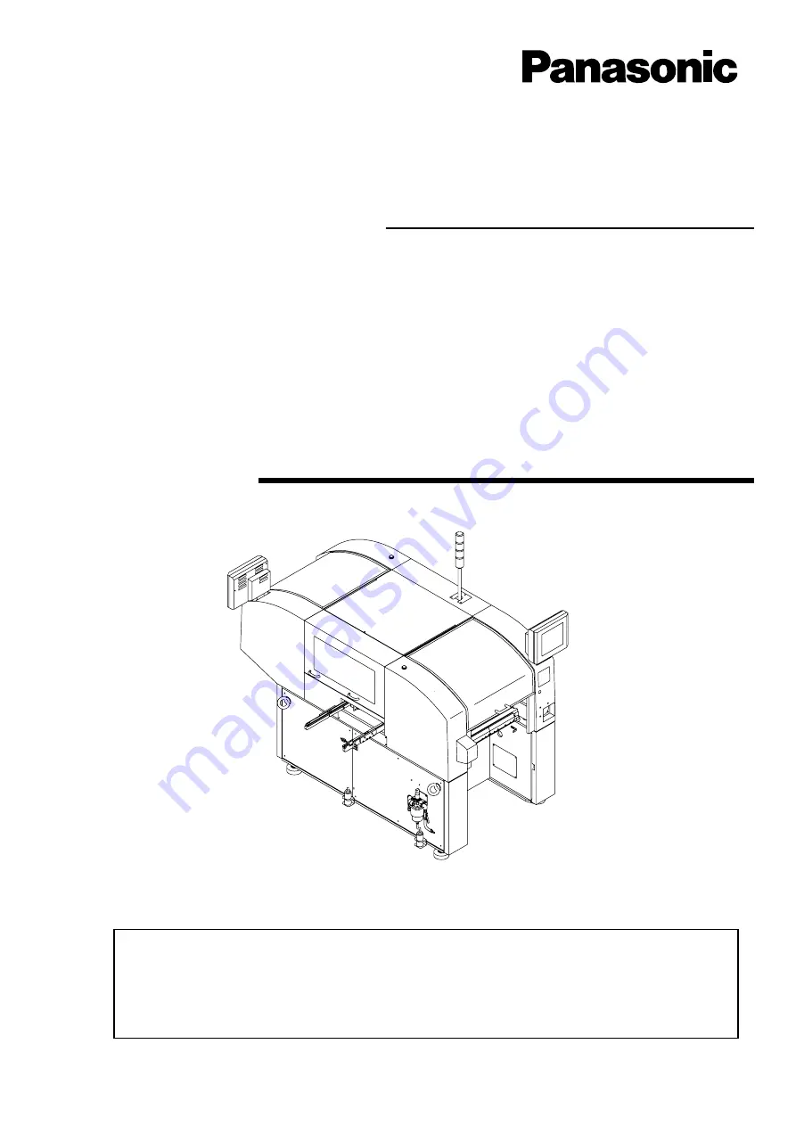
Thank you for purchasing CM301, the modular multi-functional placement machine.
Before placing the machine in service, be sure to read the instruction manual for
proper usage.
After that, store it carefully and it if necessary.

4H4C-E-OMAB-0004

Modular Multi-functional Placement Machine CM301

Operating Manual

Summary of Contents for CM301

Page 1: ...M301 the modular multi functional placement machine Before placing the machine in service be sure to read the instruction manual for proper usage After that store it carefully and it if necessary 4H4C E OMAB 0004 Modular Multi functional Placement Machine CM301 Operating Manual ...

Page 2: ......

Page 3: ...441 13 Nagahasu Tateishi machi Tosu city Saga Japan Phone number 81 942 84 2644 Fax number 81 942 84 2636 For Service and Supply of Spares in Europe you may contact Panasonic Europe Continental Europe PFAE Panasonic Factory Automation Europe Winsbergring 15 22525 Hamburg Germany Phone number 0049 0 40 85386 321 Fax number 0049 0 40 85386 332 United Kingdom PIEL Panasonic Industrial Europe U K Pana...

Page 4: ...l o v d e t a R z H 0 6 0 5 y c n e u q e r F V 0 1 0 4 T 0 4 T D V 0 0 1 C A e s a h p e l g n i S e g a t l o V d e t a R z H 0 6 0 5 y c n e u q e r F V 0 1 D 1 0 3 M C m o r f d e i l p p u S 0 4 T 0 4 T D U V 0 0 1 C A e s a h p e l g n i S e g a t l o V d e t a R z H 0 6 0 5 y c n e u q e r F V 0 1 U D 1 0 3 M C m o r f d e i l p p u S r e w o P 1 0 3 M C A V k 5 1 x a M T 0 4 T D A V k 0 1 ...

Page 5: ...rking purpose The production data of the line including this machine are programmed on PT Refer to the instruction manuals accompanied with PT Operating manual Manuals of this equipment The assembly of each unit is individually indicated by the exploded views of parts Use this list when ordering parts or confirming the assembly of parts Parts List This manual This manual is for the persons who mai...

Page 6: ...Page 4 4H4C E OMA00 B01 00 MEMO ...

Page 7: ...Operating Manual 4H4C E OMA00 A02 15 SAFETY PRECAUTIONS GENERAL DESCRIPTION BASIC OPERATION FUNCTIONS PRODUCTION SETTING PRODUCTION MATERIALS FILE OPERATION DATAMODIFICATION TEACHING CHANGING THE PRODUCTION BOARDS OPTION APPENDIX ...

Page 8: ...ication 1 17 1 4 2 Available Feeders 1 18 1 4 3 Nozzle Specifications 1 19 Chapter 2 BASIC OPERATION 2 1 Operating Panel 2 2 2 2 Touch Panel 2 3 2 2 1 Touch Panel Configuration 2 3 2 2 2 Function Keys 2 4 2 2 3 Switch Types and How to Operate 2 6 2 2 4 Messages 2 9 2 3 Main Menu 2 10 2 4 Engineer Mode 2 12 2 4 1 How to Enter Engineer Mode 2 12 2 4 2 How to Change Password 2 13 Chapter 3 FUNCTIONS ...

Page 9: ... Output Check 3 25 3 4 9 Axis Information 3 26 3 4 10 Recognition Device Maintenance 3 26 3 4 11 Ring Load Information 3 26 3 5 Machine Settings 3 27 3 5 1 Switches for Adjustment 3 27 3 5 2 Pick up Position Learning 3 28 3 5 3 Defective Head 3 28 3 5 4 Setting Time 3 29 3 5 5 Setting Backlight 3 29 3 5 6 Customizing Operator Mode 3 30 Chapter 4 PRODUCTION 4 1 Production Work Flow 4 2 4 2 Before P...

Page 10: ...eder Tables Motion in Supplying Chips 5 14 5 3 3 Supplying Chips to Tape Feeder 5 15 Chapter 6 FILE OPERATION 6 1 Loading Data 6 2 6 2 Loading and Saving the Machine Parameter 6 3 6 2 1 Loading the Machine Parameter 6 3 6 2 2 Saving the Machine Parameter 6 4 6 3 File Operation of the Floppy Disk 6 5 Chapter 7 DATA MODIFICATION 7 1 Data Modification Menu 7 2 7 2 PCB Data 7 3 7 3 Board Recognition D...

Page 11: ...on Teaching 8 18 8 5 1 Chip Recognition 8 18 8 5 2 Flowchart of Chip Recognition Teaching 8 18 8 5 3 Before the Chip Recognition Teaching 8 20 8 5 4 Teaching Procedures Block Match Recognition 8 23 8 6 Teaching the Mount Position 8 30 8 6 1 Teaching the Mount Position 8 30 8 6 2 Creating Procedure 8 30 8 7 Pickup Position Learning Teaching 8 35 8 8 Tray Pickup Position Teaching 8 38 8 8 1 Teaching...

Page 12: ...Speed Variable Adjustment 10 2 10 1 1 Transport Speed Variable Adjustment 10 2 10 1 2 Deceleration Speed Adjustment Procedure 10 3 10 1 3 Transport Speed Adjustment Procedure 10 5 INDEX Appendix A RECOGNITION DEVICE HGR 12 4H4C E OMA00 A02 01 ...

Page 13: ...gs are only some examples of the symbolic indications This indication refers to a situation which is considered that there is imminent danger of death or serious injury This indication refers to a situation which is considered that there is a possibility of death or serious injury This indication refers to a situation which is considered that there is a possibility of only injury or physical damag...

Page 14: ...rve DANGER 4H4C E OMA00 A03 01 L06EB DO NOT OPEN THE COVER WHEN OPER ATING You will have serious injury if you touch the active part inside L02E DO NOT TOUCH AC TIVE PART WHEN OPERATING You will have serious injury if you touch the active part ...

Page 15: ...hine in a dangerous or abnormal state a breakdown or an accident will occur There are two emergency stop buttons on CM301 D Pressing any one of them stops operation Press the nearest one Remove the cause of the danger or abnormality then re start operation To reset the emergency stop button pull it M104E WARNING E MERGEN C Y STOP 4H4C E OMA00 A03 00 1 Emergency stop button At the front side E M E ...

Page 16: ...dent will occur There are two emergency stop buttons on CM301 DU Pressing any one of them stops operation Press the nearest one Remove the cause of the danger or abnormality then re start operation To reset the emergency stop button pull it M104E E MERGEN C Y STOP E MERGEN C Y STOP 1 Emergency stop button At the front side 2 Emergency stop button At the rear side CM301 DU 4X4C AA00 WARNING E M E R...

Page 17: ...OX Cut off the power supplying to the machine Turning OFF the power supply routinely Turn OFF the power supply Replacing a control part such as a sensor Disassembling or replacing parts Changing production board types or working for daily inspection Turn OFF the servo switch Placing a board onto the conveyor or removing one from there Setting production materials such as feeders 1 M73EB 2 1 2 3 RE...

Page 18: ... power supply Replacing a control part such as a sensor Disassembling or replacing parts Changing production board types or working for daily inspection Turn OFF the servo switch Placing a board onto the conveyor or removing one from there Setting production materials such as feeders M73EB 1 2 3 CM301 DU WARNING Cut off the power supplying to the machine Turn OFF the breaker that is connented to t...

Page 19: ...Page 17 SAFETY PRECAUTIONS Be sure to observe 4H4C E OMA00 A03 02 WARNING ...

Page 20: ...rming that it is safe to do so it may cause injury to the worker in front of the machine Make sure that no worker is in the front when machine starting L19EB M09E TAKE CARE NOT TO PINCH YOUR HANDS OR FINGERS You will have serious injury if your hands or fingers are caught in the conveyors during manual or automatic width adjustment TURN OFF THE SERVO SWITCH BE FORE PLACING A BOARD ON OR RE MOVING ...

Page 21: ...r carry out training by yourself or consult the manufacturer M62EB DO NOT TURN OFF THE SERVO SWITCH DURING OPERATION The machine may get out of control and injure you Before turning OFF the servo switch bring the machine to a temporary stop state such as a single stop state and a cycle stop state or an operation stop state M63E DO NOT MOVE ANY AXES INCLUD ING HEADS MANUALLY WHILE TURNING OFF AND T...

Page 22: ...rt with dry cloth If the machine is not going to be used for a long period turn off the breaker connected with the machine M86E FIRMLY INSERT THE POWER AND OTHER PLUGS Imperfect plugging in may cause fire because of electric shock and generated heat Do not use the damaged plug or loose outlet M87E USE THE SPECIAL IZED OUTLET AND BREAKER EXCLU SIVELY If the breaker is shared be tween machines it ma...

Page 23: ... malfunction as a result of a tool left inside Before operating the ma chine verify that no tools are left inside 4H4C E OMA00 A03 01 M27E DO NOT GIVE A SHOCK TO THE ELEC TRICAL EQUIPMENTS There is a risk of an electric shock leak or malfunction of the machine M25E BE CAREFUL OF THE WEIGHT OF THE FEEDER A large feeder is so heavy that it may be damaged or injure you if it is dropped M18E DO NOT CL...

Page 24: ...bit its true performance or may break down Periodic inspection and maintenance should be carried out by a trained person in charge of maintenance according to the instructions in MAINTENANCE MANUAL M20EB DO NOT BLOCK OFF THE OUT LET OR INLET OF THE FAN The temperature inside the machine will rise and the machine may act abnormally And it may injure you Do not block off the outlet or inlet of the f...

Page 25: ...ructions on each label If a label has come off put a new one on a proper position To order a label from the manufacturer refer to PARTS LIST The positions of danger labels on the front side M32E 4H4C AA01 The labels for safety pasted on the product The positions of danger labels on the rear side 4H4C AB01 4H4C E OMA00 A03 01 Label part No ...

Page 26: ...e pasted on this machine Follow the instructions on each label If a label has come off put a new one on a proper position To order a label from the manufacturer refer to PARTS LIST The positions of warning labels on the front side The labels for safety pasted on the product 4H4C AA01 Label part No Inside the front cover ...

Page 27: ...n this machine Follow the instructions on each label If a label has come off put a new one on a proper position To order a label from the manufacturer refer to PARTS LIST The positions of danger labels on the rear side M32E The labels for safety pasted on the product 4H4C E OMA00 A03 01 Label part No 4H4C AB01 ...

Page 28: ...e as an option If installed the following warning labels are pasted on the machine Follow the instructions on each label If a label has come off put a new one on a proper position To order a label from the manufacturer refer to PARTS LIST The labels for safety pasted on the product The positions of warning labels Cutting unit Cutting unit cover 4H4C AA00 A B 4H4C 026E Label part No ...

Page 29: ...s are pasted on this machine Follow the instructions on each label If a label has come off put a new one on a proper position To order a label from the manufacturer refer to PARTS LIST The positions of warning labels on the front side The labels for safety pasted on the product 4H4C E OMA00 A03 02 4M4C AA00 Label part No ...

Page 30: ...the instructions on each label If a label has come off put a new one on a proper position To order a label from the manufacturer refer to PARTS LIST The labels for safety pasted on the product 4H4C E OMA00 A03 02 The positions of warning labels on the front side The positions of warning labels on the rear side 4M4C AA00 4M4C AD00 Label part No Reverse side ...

Page 31: ...4X4C AA00 The labels for safety pasted on the product The positions of danger labels on the rear side 4X4C AB00 0 1 K 1 B DANGER DO NOT OPEN THE COVER WHEN OPERATING You will have serious injury if you touch the active part inside 0 1 J X A DANGER DO NOT TOUCH ACTIVE PART WHEN OPERATING You will have serious injury if you touch the active part 0 1 K 1 B DANGER DO NOT OPEN THE COVER WHEN OPERATING ...

Page 32: ...e positions of warning labels on the rear side 0 1 P 9 B WARNING DO NOT DISABLE SAFETY SENSOR You will have serious injury by active part if you disable safety sensor 0 1 N M B WARNING WORKER OPERATING IN THE BACK Make sure that no worker is in the back when machine starting 4X4C AB00 0 1 P 9 B WARNING DO NOT DISABLE SAFETY SENSOR You will have serious injury by active part if you disable safety s...

Page 33: ...per position To order a label from the manufacturer refer to PARTS LIST Label part No 0 1 J Q B feeder tables will have serious injury The labels for safety pasted on the product The positions of warning labels Cutting unit Cutting unit cover 4H4C AA00 View seen from A 4H4C 022E View seen from B A 0 A 5 F B WARNING TAKE CARE NOT TO TOUCH CUTTER You will have serious injury if you touch cutter 0 1 ...

Page 34: ...l have serious injury if you touch the active part inside 4H4C E OMA00 A03 00 Direct Twin Tray Feeder DT40T 40U Danger Labels The following warning labels are pasted on this machine Follow the instructions on each label If a label has come off put a new one on a proper position To order a label from the manufacturer refer to PARTS LIST Label part No 0 1 J Q B feeder tables will have serious injury...

Page 35: ...anufacturer refer to PARTS LIST Label part No 0 1 J Q B feeder tables will have serious injury The labels for safety pasted on the product The positions of warning labels on the front side The positions of warning labels on the rear side 4M4C AD00 0 1 J K A 0 1 P 9 B WARNING DO NOT DISABLE SAFETY SENSOR You will have serious injury by active part if you disable safety sensor 0 1 N 8 A WARNING WATC...

Page 36: ...y Switch for Maaintenance 1 Key switch for maintenance at our company This switch which is targeted for the technician belonging to our company or the commissioned maintenance technician can release all of the safety cover interlocks It is used for such an exten sive maintenance work as you cannot perform 2 Feature of key switch for maintenance at our company It is dangerous to use this maintenanc...

Page 37: ...ution label for this product are attached to the machine Operate and maintain the machine according to instructions on the label The label below is not attached to the machine without the lead checker CLASS 1 LASER PRODUCT AAA0046A LASER EMITTING AVOID DIRECT EXPOSURE Never diassemble LASER UNIT AAA0047A AAA0048B ...

Page 38: ...t be loaded by improper handling Make sure to back up the program and data on a disk to protect against the loss of data To back up the program and data make another copy disk of the same contents 2 Write Protection The stored data may be mechanically protected from accidental erasure or rewriting Write protection may be set or disabled by sliding the write protect tab located at the lower part of...

Page 39: ...ovided for safekeeping and carrying A disk should not be stored or left in areas exposed to the following conditions Do not apply excessive force to the disk Do not place heavy objects on the disk Automatic shutter The automatic shutter should not be opened Do not touch the magnetic circu lar disk inside Refrain from smoking drinking and eating close to the disk Any loose labels should be re place...

Page 40: ... this machine indicates the model name and production number 4X4C AB00 CM301 DU CM301 D 4H4C AB01 4H4C E OMA00 A04 05 Actual numbers are shown on the plate instead of Actual numbers are shown on the plate instead of CM301 D KXF 4H4C CM301 DU KXF 4X4C ...

Page 41: ...39 4H4C E OMA00 A04 02 DT40T 40 DT40T 40U Actual numbers are shown on the plate instead of 4M4C AD00 4M4C AD00 DT40T 40 KXF 4M4C Actual numbers are shown on the plate instead of SERIAL PLATE DT40T 40U KXF 4Y4C ...

Page 42: ...hips and oil discharge when the air is coming out use safety glasses for protection 1B4C 442E 1D4C 406E 4H4C AB01 Bolt with hexagonal hole Air spring Position to drill the air spring 15 mm to 20 mm Hole Position to use the air spring ABOUT DISPOSAL OF COMPONENTS CONTAINING MERCURY NOTICE This product has a fluorescent lamp that contains a small amount of mercury It also contains lead in some compo...

Page 43: ...IS MANUAL In this manual the following mark are used for description Title Actual operation Supplementary description Operation step number Shows operation flow Shows a reference item Shows the operation for engineers Shows the operation for operators Shows pressing a key on the touch panel Means pressing UNLOCK and then START on the operating panel within 2 seconds Means pressing B key while hold...

Page 44: ...pecification CM301 D Front view Rear view Standard Specification 4H4C AG00 4H4C AH00 External view Specification Front view 4M4C AD00 Rear view 4M4C AA00 DT40T 40 CM301 DU Front view Rear view 4X4C AA00 4X4C AB00 Front view 4M4C AD00 Rear view 4M4C AA00 DT40T 40U For further information about the specification see 1 3 Equipment Specification in the Operating Manual 4H4C E OMA00 A04 00 ...

Page 45: ...escribes the following Names and Mechanism of Each Unit This describes the names and mechanism of each unit by using illustrations Production Process This describes the mounting process in due order Specification This describes the specification of the equipment and available boards 4H4C AD00 ...

Page 46: ... 1 1 Placement Machine CM301 External View Front View Status Indicator 3 color Indicator Light Front Panel Power Supply Switch Rear View Feeder Table Front Safety Cover Rear Panel Rear Safety Cover Rear Side Cover 4H4C AA01 4H4C AB01 Front Side Cover Side Safety Cover ...

Page 47: ... Mechanism of Each Unit Inside the cover 443C 101P Operating Panel 2 1 Used to start stop the machine and so on Floppy Disk Drive Used to write and read pro gramming data Power Supply Switch Used for ON OFF power switch of machine OFF ON SERVO 443C 101P STOP UNLOCK STEP START LIGHT ON SELECT KEY LOCK KEY LOCK BACK LIGHT OFF BACK LIGHT OFF E MERGEN C Y STOP RELEASE TRIP O F F ON R E S E T Front Vie...

Page 48: ...ator knob 444C 101P 4H4C AA01 e c n a r a e p p A r o l o C g n i n a e M e s u a C t i L n e e r G r o n o i t a r e p o c i t a m o t u a g n i r u D g n i n n u r t n e m t s u j d a e n i h c a m y l l a m r o n g n i n n u R g n i k n i l B w o l l e Y h c i h w g n i n r a w r o e l b u o r T n o i t a r e p o e u n i t n o c n a c u o y p o t s e l c y C e t a i d e m m I s l a i r e t a m ...

Page 49: ...rds in and out 010WC0AA01 4H4C 018E 160JC0AA01 030CC0AA01 4H4C E OMA01 A01 00 Transfer Head Picks up chips and mounts them onto the board Each head unit has two transfer heads Nozzle Picks up chips using a vacuum pressure Various sizes and shapes of nozzles support various chips Head Camera Used for board recog nition thermal correc tion and calibration 444C 405E 4H4C AI00 ...

Page 50: ...the chips from minute ones to large sized and unusual shaped ones 010VC0AA01 4H4C AJ00 160KC0AA00 4H4C 016E 4H4C E OMA01 A01 01 Tape Feeder Table This is composed of the table where the tape feeders are set and the tape feeding part which drives feeders The tape feeding part operates even if the vibratory stick feeder is used however this is not out of order ...

Page 51: ...ng it between Y and Z directions and hold it at the mount height during mounting X Y Unit Moves the head unit to the appointed position quickly and precisely 4H4C AK00 010UC0AA01 4H4C E OMA01 A01 00 Nozzle Changer Two in All Changes nozzles automatically during production 15VHC0AA01 0503C0AA01 4H4C AL00 ...

Page 52: ... b Line Camera The line camera is set on the frame of main body and recognizes chips positioning deviation inclination chipping etc Line camera Board Process Two chips are scanned and recognized in a row by moving the head so that it will move across the line Start Batch recognition 4H4C 004E Line width 50 mm 4H4C 002E Recognition image Reference position Board Y X 4H4C 003E 016JC0AA 4H4C E OMA01 ...

Page 53: ... Knob Handle for Carry Supply Complete Switch B Side Chip Supply Area B Side Magazine Door B Side Coupling Settlement Knob Two in All Trash Box B Side Supply Complete Switch A Side Chip Supply Area A Side Magazine Door A Side Caster for Installation Four in All Adjuster Bolt for Transport Four in All Trash Box A Side Names and Mechanism of Each Unit 4H4C E OMA01 A01 00 ...

Page 54: ...of Each Unit 4H4C E OMA01 A01 00 Main Units Multi step Tray Drawer Draws out tray pallets from the magazine and contains them Multi step Tray Lift Moves the multi step tray drawer upward and downward 0909C0AA01 0908C0AA02 4M4C AB00 ...

Page 55: ...1 11 GENERAL DESCRIPTION 1 4M4C AC00 Names and Mechanism of Each Unit 4H4C E OMA01 A01 00 Multi step Tray Magazine Contains ten tray pallets Tray Pallet Trays can be set on this pallet 040KC0AA00 040JC0AA00 ...

Page 56: ...ounts chips the other head unit picks up and recognizes chips Transporting board in 1 A board is transported in from the previous process 2 The board is clamped and recognized Mounting chips 444C 106E H2 From previous process To next process Rear side Front side H1 3 4 5 5 2 3 4 1 3 Picking up chips 4H4C 016P 4H4C 006E Tray Feeder Supply Area 4H4C 006P 5 Mounting the chips 4H4C 017P 4 Recognizing ...

Page 57: ...RIPTION 1 Mounting Mechanism 3 After the chips have been mounted on the board it is transported out to the next process Transporting board out 6 The board is transported out to the next process 4H4C 018P 4H4C E OMA01 A01 00 ...

Page 58: ...q e r F V 0 1 U D 1 0 3 M C V 0 0 4 C A s e s a h p 3 e g a t l o v d e t a R z H 0 6 0 5 y c n e u q e r F V 0 1 0 4 T 0 4 T D V 0 0 1 C A e s a h p e l g n i S e g a t l o V d e t a R z H 0 6 0 5 y c n e u q e r F V 0 1 D 1 0 3 M C m o r f d e i l p p u S 0 4 T 0 4 T D U V 0 0 1 C A e s a h p e l g n i S e g a t l o V d e t a R z H 0 6 0 5 y c n e u q e r F V 0 1 U D 1 0 3 M C m o r f d e i l p ...

Page 59: ...g Area 1 3 3 Board Flowing Direction Dead Space Board Board Transport Space Fixed Side Unit mm Board Flowing Direction Standard Reference Position Operator Automatic Width Adjustment Fixed Side Change of board flowing direction and reference position can be supported as options Mount data reference can be set optionally by PT 4H4C 007E 444C 110E 3 4 30 4 20 25 6 5 3 4H4C E OMA01 A01 01 Z Y Y X ...

Page 60: ...Tape Small Reel Board Transport Height 900 Unit mm 4H4C 008E Equipment Specification DU 950 4H4C E OMA01 A01 00 A A A A A A A A A A A A A A A A A A A A 1 425 125 695 495 1 555 850 2 638 1 791 5 1 624 6 222 1 013 5 700 700 700 195 1 090 55 55 980 195 1 580 105 385 1 430 1 595 2 000 ...

Page 61: ...med on the basis of the positional relation be tween the recognition mark and the circuit pattern A certain contrast is required between the recognition mark and the board Binary contrast image Mark Size and Background A certain size of neutral area that is different from the mark is required for the back ground of mark a 0 2 mm 433C 019E 444C 113E Mark Transport Direction L Length W Width T Thick...

Page 62: ...e p y T 9 M l e e r l l a m S φ 8 7 1 l e e r e g r a L o t p u φ 2 8 3 m m 8 s s o b m E r e p a P l l a m S m m 1 2 7 2 e g r a L m m 1 2 7 2 m m 2 1 s s o b m E l l a m S m m 1 2 7 2 e g r a L m m 2 4 3 1 m m 6 1 s s o b m E e g r a L m m 2 4 3 1 m m 4 2 s s o b m E e g r a L m m 2 4 3 1 m m 2 3 s s o b m E e g r a L m m 3 6 9 m m 4 4 s s o b m E e g r a L m m 3 6 9 m m 2 3 e v i s e h d A e g ...

Page 63: ...tion 4H4C E OMA01 A01 00 1 4 3 Nozzle Specifications This machine has 5 types of standard nozzles to be used for various parts Nozzle No Shape Nozzle No Shape Nozzle No Shape 1001 1002 1003 1004 1005 433C 001P 433C 002P 433C 003P 433C 005P 433C 004P ...

Page 64: ...Page 1 20 MEMO 4H4C E OMA01 A01 01 ...

Page 65: ... chapter describes the basic operation This includes how to operate the operat ing panel touch panel and the functions You can choose an item by pressing its icon or button on the screen 4H4C E OMA02 A01 02 Chapter 2 BASICOPERATION ...

Page 66: ... l e n a p g n i t a r e p o f o e s u e h t n e h w s t h g i l p m a l e h T s t h g i l p m a l s i h t f f o s n r u t l e n a p h c u o t f o t h g i l k c a b e h t e l i h W h c t i w s o v r e s O V R E S t r a p e l i b o m e h t o t n i s d n a h r u o y t r e s n i u o y n e h W r o t o m e h t r o f h c t i w s r e w o p a s i s i h T h t o b N O n r u t n o i t c u d o r p t r a t s u...

Page 67: ...tate of current displayed screen is displayed by the icon and the item name This is the same icon as appears in the Main Menu 2 3 Main Menu e g The screen as shown left This shows this machine has come to an immediate stop in the engineer mode during production c Date Time and Data Name Display Area Present date time and data name are dis played d State Display Switches and Mes sages Area The stat...

Page 68: ... e r c s n o i t i n g o c e r d e s s e r p e z i s 2 1 t f e l r e p p u t h g i r r e p p u e z i s 2 1 t h g i r r e w o l e z i s 2 1 t f e l r e w o l e z i s 2 1 t o n d e y a l p s i d n o i t c e l e s e g a u g n a L e l g g o t l l i w e s e n a p a J r o h s i l g n E s e g a u g n a l e h t y e k s i h t s s e r p u o y n e h W p o t s r e z z u B g n i d n u o s s i t i n e h w r e z...

Page 69: ...ree screen Help This key is used to display an explanation or operation instruction of a function 1 Press The help screen is displayed Every time you press the position of the message changes alternately Left Right To exit Help press ESC Screen is scrolled in the direction of arrow Touch Panel 444C EEn DmAd 001 444C EEn Main 001 444C EEn Main 003 4H4C E OMA02 A01 01 ...

Page 70: ...witches Input Switches Typing numeric value 1 Select the item to be input if there is more than one item to be input Specified item will blink or will be highlighted 2 Enter values with numeric keys If you pressed an incorrect key press BS and re enter a correct value The entered value is displayed in the numeric value window 3 Press ENT The value of specified item changes to the newly entered val...

Page 71: ...anged Blue letters on a light blue ground show the selected stage The following is displayed at the rear operating panel Changing stages on the line 1 Every time you press the numeric key displayed stages are changed E g When two CM301s are connected pressing this key switches the stage in sequence from 1 2 3 4 Pressing set displays numeric keys so you can switch the stage also by entering the num...

Page 72: ...tches Page of displayed screen is turned Move Switches Cursor moves in the direction of arrow Not all the cursors are arranged as shown left Mark on Switch Repeat Mark at the upper right If a switch with this mark is kept pressed its function is executed continu ously Unlock Mark at the upper left A switch with this mark must be pressed in combination with the UNLOCK button Touch Panel Vertical di...

Page 73: ...ge e g a s s e m n o i t c u r t s n I e g a s s e m n o i t u a c g n i n r a w r e g n a D e g a s s e m y r i u q n I e g a s s e m n o i t i b i h o r P e g a s s e m g n i t i a w e m i T e g a s s e m n o i s l u p m o C d n u o r g e u l b a n o k r a m e t i h W e g a s s e m r o r r E d n u o r g w o l l e y a n o k r a m k c a l B e m a r f k c a l b n i 444C 107TE 4H4C E OMA02 A01 02 ...

Page 74: ... period is approaching to 90 of its cycle the message is displayed in green When the inspection period has passed it is displayed in yellow When the message is displayed inspect this machine referring to the maintenance manual 3 Icon switches Pressing each icon displays its menu screen Screen of Engineer Mode 4 This icon indicates engineer mode 5 Pressing this will switch to the dis play of the ma...

Page 75: ...c s a h c u s r o f d e s u s i s i h T e l i F t n e m e g a n a m d r a h T P a i v s r e t e m a r a p e n i h c a m d n a a t a d n o i t c u d o r p e h t d a o l e v a s o t d e s u s i s i h T k s i d y p p o l f d n a k s i d e n i h c a M r e t e m a r a p o t e u d t n e m p i u q e e h t f o c t e e u l a v e c n e r e f e r e h t t e s d n a e g n a h c o t d e s u s i s i h T l a u n ...

Page 76: ... it referring to 2 4 2 How to Change Password 1 Press Engineer Password input screen is displayed 2 Enter the password then press Decision The main menu of engineer mode is displayed If you pressed an incorrect key press BS and re enter a correct letter Pressing switches engineer mode to an operator mode 444C EOP Main 001 2 1 4H4C E OMA02 A01 01 ...

Page 77: ...ew password then press Decision Enter between 1 and 10 letters 5 Enter the new password again then press Decision When the password entered at the step 4 is the same as the one entered at the step 5 it is changed and the main menu of operator mode is displayed 6 Press Engineer and make sure you can enter engineer mode with the new password If you cannot enter engineer mode perform this procedure f...

Page 78: ...Page 2 14 MEMO 4H4C E OMA02 A01 01 ...

Page 79: ... 4 PRODUCTION The following are described in this chapter 3 2 Production Settings 3 3 Production Information 3 4 Machine Adjustment 3 5 Machine Settings Refer to the Maintenance Manual Chapter 6 FILE OPERATION Chapter 7 DATA MODIFICATION Data modify Reference Outline of function Menu configuration PCB data Describes checking and modifying board data 7 2 Board recognition data Describes checking an...

Page 80: ...scribes displaying the information during running 3 3 1 Run Information Describes calculating the consumption of chips to the count of production boards 3 2 3 Calculating Chip Consumption Displays the chip pick up information during production 3 3 3 Pick up Information Describes displaying the factors that made the machine stop during production 3 3 2 Stop Information Performance info Product conf...

Page 81: ...the conditions for the motions for production 3 5 1 Switches for Adjustment Describes loading saving machine parameters Chapter 6 Sub operation Describes loading production data Chapter 6 Main operation Refer to the Mainte nance Manual File managment Machine parameter Machine config Machine adjust Displays the tape feeder library data 7 11 Feeder Library Displays the recognition library data 7 11 ...

Page 82: ...s This is used for the settings requisite for production and to check the motion 1 Press Product config on the main menu Production config menu is displayed Pressing a function switch displays each setting screen 4H4C E OMA03 A01 02 ...

Page 83: ...how to change nozzles see 9 4 Nozzle Exchange NOTICE Take care not to misset the nozzle or it will be damaged For example when the nozzle is set on the head the No 11 on the nozzle changer is vacant If another nozzle is set in the No 11 by mistake the nozzles will collide with each other because the machine will put the nozzle on the head back to the No 11 in changing nozzles Production Settings 4...

Page 84: ...calculate the consumption of chips to the count of production boards beforehand Enter the count of production boards with numeric keys then press Run The number of the chips required to be set in the feeder is calculated and displayed Next Page Tape Cut Timing Setting Option When changing the number of times of cutting the length of the empty tape must be the value or under in the following list 4...

Page 85: ...The number of chips per pallet Mount Board The number of the chips to be mounted per board Skip Board The number of the mounting skip points per board Total Chip The consumption of chips to the count of boards Reel H1 The number of tape reels required for the count of boards H2 The number of pallets required for the count of boards Chip Count Mounting Board Skip Board 4H4C E OMA03 A01 02 Board Cou...

Page 86: ...eing transported its image is blinking After pressing PCB transfer on the production settings menu make sure the servo switch is ON and then press UNLOCK START UNLOCK Carry in Transports the board in from the previous process to the left conveyor UNLOCK Load Transports the board from the left conveyor to the right conveyor UNLOCK Carry out Transports the board from the right conveyor out to the ne...

Page 87: ...u will check Select the tray you will check Only when H2 is selected Reset Resets the number of the residual chips pointed by a cursor now Pressing and moves a cursor up and down All reset Resets the number of the residual chips on all the feeders When the message appears press Yes Call by Adrs Pressing this switch displays the input screen When you enter an address and press ENT a cursor moves to...

Page 88: ...rmation of parts including the chip information of the feeder pointed by a cursor is displayed Move a cursor to the address you would like to display then press this switch Angle Definition Angle definition Pressing this switch displays the screen as shown left The angle definition of the main chips in picking up and mounting is displayed 4H4C E OMA03 A01 02 ...

Page 89: ...rt Pins This part describes changing support pins together with board support blocks Detailed information about how to change them 9 3 Setting the Support Pin Board support blocks rise up so that you can draw out them Board support blocks lower 4H4C E OMA03 A01 03 ...

Page 90: ...ata All Adrs Displays all addresses Displays the next pick up position for each tray as an X Y arrangement Empty is displayed at the head of the chip address where production cannot be continued due to the lack of chips Changing the Pick up Start Position Pressing moves a cursor to the field of the arrangement of the tray whose position will be changed Pressing changes the value Increases the valu...

Page 91: ...eject pallet then Reset to delete this memory Next time the chip are ejected on from the first position onward again Changing Parts a Changing Tray Draws out the specified tray pallet to the supply position Select the desired tray using and press UNLOCK Tray change b Changing Magazine Used when changing tray magazines Press UNLOCK MagazineChange c Changing Defective Chip Eject Pallets Draws out th...

Page 92: ...s actually drawn out the machine puts the pallet back to the address 6 when an operation resumed However the pallet of the address 6 has been at the address 6 so the pallets collide with each other If worst comes to worst the tray feeder itself will be damaged 4H4C E OMA03 A01 02 Production Settings 3 2 9 Motion Setup This part describes how to set up the machine s motion Both side Mount Unuse Whe...

Page 93: ...bled Motion configuration The item is hidden Enabled Disabled Transport operation Both side mounting is Disabled Both side mounting is enabled Both side mounting is enabled NOTICE By default OFF is selected This data will not be changed unless a user changes this setting When mounting the board whose reverse side has been mounted be sure to set Both side Mount to Use If it is set to Unuse the chip...

Page 94: ...t passed through Blocks to process The number of blocks produced mounted actually Operating rate Rate of the time when the machine is actually working for mounting during the production mode Real run time Total run time Machine run ratio Running rate of the specified stage alone adding Wait for proc time to Real run time Real run time Wait for proc time Total run time Real run time The time found ...

Page 95: ... Stop history Displays the stop histories the screen as shown below of the selected stage Stop History The latest 20 stop histories occurred during an automatic operation are displayed These are used to select stop information Error scrn Displays the error screen displayed when the machine was stopped Axis informati on Displays the axis information when the ma chine was stopped 3 4 9 Axis Informat...

Page 96: ...Without reset data will be added on irrespective of switchover of board types Count on Pick up information screen Pick up miss Recog miss For each feeder The pick up information of the selected stage is displayed for each feeder Displayed only when the tray side stage is selected Every time you press the screens are changed over For each nozzle The pick up information of the selected stage is disp...

Page 97: ...used to reset production information Choose the information you would like to reset It is possible to choose more than a piece of information at a time When you press the switch again it is canceled Press Run Press Yes when the message appears 1 2 4H4C E OMA03 A01 03 ...

Page 98: ...djust on the main menu Machine adjustment menu is displayed Pressing a switch displays each setting screen 3 4 1 Returning to Origin This is used to return all the axes to their origins Make sure no board is on the conveyor beforehand After you have pressed Return to origin on the machine adjustment menu make sure the servo switches are ON and then press UNLOCK START All the axes return to their o...

Page 99: ...l board width enter it with numeric keys Press UNLOCK Run The rails are adjusted automatically 3 4 3 Board Transport This is used to perform each step from transporting board in to transporting it out to the next process After you have pressed PCB transfer on the machine adjustment menu make sure the servo switches are ON and then press UNLOCK START The board transport screen is displayed The oper...

Page 100: ...ick up and Mounting Motions This is used to check the pick up recognition and mounting position of the chosen head or nozzle When AR is selected Choose the desired stage Choose a head or a center Press UNLOCK Each position key The chosen head moves to that position In the Pick up field set the address and type When AR is selected press first then select a tray In the Mount field choose the X Y coo...

Page 101: ... change over in sequence from Slow Mid Fast Slow UNLOCK Draws out the specified tray pallet to the pick up position UNLOCK Draws out the specified tray pallet to the lifter position at that height UNLOCK Draws out the specified tray pallet to the supply area UNLOCK Puts the tray pallets drawn out to the pick up position and the supply area back to the magazine Machine Adjustment 4H4C E OMA03 A01 0...

Page 102: ...lay Display for Each Address The states of the input addresses the machine uses are displayed with names for each bit Highlighted name shows its bit is ON 1 When you press the Name button the state of that bit is checked and displayed again Call by No Displays the address that includes the speci fied No at the left side of screen Address List 4H4C E OMA03 A01 01 ...

Page 103: ...ing of the board holder side clamp and upper lower clamp Head A Head B Works the vacuum valve of the head Display for Each Address The states of the output addresses the ma chine uses are displayed with names for each bit Highlighted name shows its bit is ON 1 When you press the Name button with UNLOCK pressed the signal opposite to the current state is output and displayed again Call by No Displa...

Page 104: ...tate of status address error puls in a turn of each axis in bit Pulse in a turn This data is sampled and displayed against X and Y axes only Meaning of abbreviation X X axis of X Y unit Y Y axis of X Y unit ZA ZA axis θ A θ A axis ZB ZB axis θ B θ B axis 3 4 10 Recognition Device Maintenance This is used to check all the recognition processing motions For information about how to operate it refer ...

Page 105: ...cape Pressing Default or restarting the machine returns the settings to the usual ones Tape feed When it is ON tape feeding by the feeder is enabled Pickup When it is ON pick up motion is enabled Chip recognition When it is ON chip recognition and error check is enabled Mount When it is ON mounting motion is enabled Recovery When it is ON re pickup of the pick up error and recognition error chips ...

Page 106: ... to check the state of the head and specify reset the defective head The button of the head which has become defective automatically during production is colored according to the factor The defective head will not be used for production When canceling it after checking press the button of the head you would like to cancel Then the color of the button returns to a normal color light gray When you w...

Page 107: ...hen press Set The current time is changed Forwards the time Reverses the time 3 5 5 Setting Backlight This is used to set the backlight off time When the touch panel is not used for the set time the backlight of the touch panel will turn off To turn on the backlight again press Press the desired time As long as Unuse is pressed the backlight will be ON all the time 4H4C E OMA03 A01 01 LIGHT ON ...

Page 108: ... the engineer mode Press the switch of the function you would like to use in the operator mode Every time you press it the display changes alternately Use Unused Default Returns all the displays to Unused Main menu in the operator mode The icons of the functions you have set Use are displayed on the main menu in the operator mode then you can use those functions Individual Function Selection Scree...

Page 109: ... During a stop to wait for a board 3 During a temporary stop Depending on circumstances the machine may begin running unexpectedly espe cially 2 During a stop to wait for board and 3 During a temporary stop When putting hands into the machine make sure servo switch is OFF or power supply is OFF Daily Production This chapter describes the basic operation for automatic operation the basic work again...

Page 110: ...ction Perform the operation to finish production Production finishes 3 Starting production 4 3 2 Starting Operation Perform the operation to start production Production starts File operation Data loading etc Troubleshooting of board recognition error etc 2 Starting up machine 4 3 1 Starting up Machine Turn on the power supply switch to start up the machine Adjust the equipment if it is in bad cond...

Page 111: ...overs closed Are emergency stop buttons reset SAFETY PRECAUTIONS State of emergency stop State of reset Are there any foreign objects on conveyors or feeder bases Chips Tools Emergency stop button 433C 039E 433C 040E Front View Rear View Pull it forward to reset Front Safety Cover 4H4C AN00 4H4C AN00 4H4C AN00 4H4C AO00 Rear Safety Cover Side Safety Cover ...

Page 112: ...9 MPa or more and 0 78 MPa or less Tray Feeder 0 30 MPa or more and 0 35 MPa or less Make sure the lever is ON If air pressure is improper turn the valve and adjust it 1 Unlock the valve 2 Adjust the air pressure 3 Lock the valve Valve Pressure Gauge Lever To turn it ON throw it down 4H4C 001P ON Front Side 4H4C AN00 4H4C E OMA04 A01 00 4H4C 002P 3 Lock the valve 2 Adjust the air pressure 1 Unlock...

Page 113: ...ncy stop button out resets it 4 3 1 Starting up Machine Start up the machine in the following order 1 Turn ON the power supply switch Power is supplied to the machine and the touch panel starts to be displayed The system starts loading to the machine It will take several minutes After the system has been loaded the screen as shown left is displayed 2 Turn ON the servo switch RELEASE TRIP O F F ON ...

Page 114: ...LOCK START The steps from self diagnosis 4 3 3 to returning to origin 4 3 4 are performed After that when a board is transported in from the previous process production starts OFF ON SERVO STOP UNLOCK STEP START LIGHT ON SELECT KEY LOCK KEY LOCK BACK LIGHT OFF BACK LIGHT OFF 1 2 Starting Production 4H4C E OMA04 A01 01 ...

Page 115: ...chine is checked automatically When the state is normal Return to origin screen is displayed If any trouble is detected during a self diagnosis the following screen is displayed E g If any trouble is detected the trouble item is displayed Refer to Maintenance Manual to solve the trouble Starting Production 4H4C E OMA04 A01 01 ...

Page 116: ...Starting Production 4 3 4 Returning to Origin Before mounting each axis returns to its origin All the axes return to their origins Complete is displayed for the axes returned to their origins 4H4C E OMA04 A01 00 ...

Page 117: ...hine Cycle time The time from when the board starts to be loaded onto the mounting stage until when it starts to be unloaded after it has been mounted Mount points The number of the chips which have been mounted Cycle stop 4 5 1 Stop Operation If you want to stop production temporarily after the current board is mounted press this switch Parts empty Chapter 5 SETTING PRODUCTION MATERIALS The addre...

Page 118: ...r hands or body inside the active part 4 5 Production Stop 4 5 1 Stop Operation Immediate Stop For Stopping Production Immediately 1 Press STOP on the operating panel Production is stopped immediately and the immediate stop screen is displayed 2 When resuming production press UNLOCK START on the operating panel Production is resumed When stopping production press Then the main menu is displayed OF...

Page 119: ... mounted production stops And the cycle stop screen is displayed When you press Cycle stop again before the machine is stopped the cycle stop is canceled 2 When resuming production press UNLOCK START on the operating panel Production is resumed When stopping production press Then the main menu is displayed Production Stop 4H4C E OMA04 A01 03 ...

Page 120: ...e engineer mode requires the password Parts empty Info Displays the addresses and parts names of the empty feeders The button will be displayed only when the machine is stopped due to lack of chips Prod conf Used to change the production setup 3 2 Production Settings Data modify Used to modify production data Chapter 7 DATA MODIFICATION Maintenance Used to enter the maintenance mode Refer to the M...

Page 121: ...g screen printer etc When this machine gets the signal it automatically enters a state of production completion after producing the last board and the main menu screen is displayed 4 6 2 Finishing Machine When the main menu is displayed turn off the power of the machine in the following step 1 Turn OFF the servo switch 2 Turn OFF the power supply switch RELEASE TRIP O F F ON R E S E T OFF ON SERVO...

Page 122: ...Page 4 14 MEMO 4H4C E OMA04 A01 01 ...

Page 123: ...ile on the tray To supply chips take out the pallet where the tray is set Chips can be exchanged also by the magazine Tape Feeder Option Chips are fed by the reeled tape Chips are supplied by changing tape feed ers Bulk Feeder Option Chips are fed by the bulk cassette Chips can be supplied while the feeder is set on the feeder table Bulk feeder supporting unit option is required For information ab...

Page 124: ...Fit the tray to the tray guides 2 Loosen the two rail locking screws 3 Put the tray between the tray clamp and the tray guides by moving the rail 4 At this position lock the rail by tight ening the rail locking screws 5 Loosen the locking screw of the side support 6 Fit the side support to the tray side and tighten the locking screw 7 Put the tray on the pallet with the tray clamp released and cla...

Page 125: ...ase lever to the direction of arrow will release the clamp and the state will be the same as the state b State b Tray Released In this state turning the clamp lever to the direction of 1 a little will release the release lever And turning the clamp lever to the direction of 2 will clamp the tray Release Lever 1 2 Clamp Lever 443C 143P 443C 144P ...

Page 126: ...is 12 mm or over When setting a different shape tray judge whether the pallet is the one with the offset block or an ordinary one and then use it Chips may not be picked up because the data position is deviated Setting Trays Block Fixing Bolt Washer CM301 Standard Specification Pick up Position Condition Range Tray Max 335 mm Tray Setting Reference Tray Origin Pick up Position Chip Center Specific...

Page 127: ...ize choose two offset block setting positions from among four ones 3 Set the offset blocks 4 Set the tray onto the tray pallet How to Set 5 1 1 Setting Tray onto Pallet When the offset blocks are set modifying the pallet data is required Programming Manual Stock Data Setting Position 4 Offset Block Setting Position 3 Setting Position 2 Setting Position 1 4H4C 037P 4H4C 039P 4H4C 038P 4H4C 040P ...

Page 128: ... magazine into the tray feeder 1 Set the tray pallets into the tray maga zine Ten pallets can be set in one tray magazine 2 Press Tray counter on the Produc tion config menu screen 3 Select the tray feeder to set 4 Press UNLOCK MagazineChange Setting Trays 4H4C E OMA05 A01 02 4H4C 011E 040KC0AA00 2 1 To the next page ...

Page 129: ...ray feeder 6 Close the magazine door 7 Select the tray where the materials are set and press Reset X 1 and Y 1 are set To set another value select the field by using and change the value by using 8 Press The Production config menu screen is displayed 4H4C E OMA05 A01 03 4H4C 019E 4H4C AE00 4H4C EEn PcTc 001 2 1 3 ...

Page 130: ... prevent a feeder setting error and tape feeding error pay attention to the follow ing point Before setting the feeders clean up the feeder setting surface of the feeder table If there are anything hard such as chips on the feeder table they deteriorate the setting precision of tape feeders Even minute chips such as 0603 cause pick up error so be careful Make sure the pick up position of tape feed...

Page 131: ...nd check the address 3 Turn OFF the servo switch and open the safety cover 4 Cut off the carrier tape that has come out of the tape feeder If a tape feeder is set without cutting off the carrier tape it is not led to the chute correctly which causes a tape feeding trouble 4H4C E OMA05 A01 03 Setting Tape Feeders 493C 016P To the next page 4H4C EEn Pc 002 OFF ON SERVO ...

Page 132: ...aking its handle lightly 6 Close the safety cover and turn ON the servo switch 7 Press Production config menu is displayed NOTICE Immediately after an operation has started make sure the carrier tape has been sent to the chute correctly Setting Tape Feeders Chute Carrier Tape Feeder Table Correct Incorrect Tape is not in the chute Tape is bending 443C 346P 443C 347P 493C 018E 443C 112E NG 4H4C 019...

Page 133: ...OFF the servo switch and open the safety cover 2 Cut off the carrier tape at the exit of the chute At this time take care not to harm the tubes and wiring of the bulk feeders option 3 Remove the tape feeder by lifting it up 4H4C 009E 4H4C 019P To the next page 4H4C E OMA05 A01 02 OFF ON SERVO ...

Page 134: ...Setting Tape Feeders 4 Cut off the carrier tape at the feeder tip Pull out and dispose of the carrier tape cut off 5 Close the safety cover and turn ON the servo switch 493C 016P 4H4C E OMA05 A01 01 OFF ON SERVO ...

Page 135: ...d the supply completion button of the tray feeder of that pallet will turn on 1 Check the address No where the chips run out in the message area The address of the tray whose chips run out is displayed 2 Open the door of the chip supply area on the side where the chips run out and take out the tray pallet 3 Replace the tray on the tray pallet How to Replace 5 1 1 Setting Tray onto Pallet 4 Set the...

Page 136: ...ose Table mode select from Production config menu 3 2 2 Selecting Table Mode Joint Mode In this mode the feeder is not divided Up to 40 types of chips can be used Spare Mode In this mode one of the divided feeder tables is not used The chips for the next board type can be set during production The chips on both the tables are used for the board A 4H4C E OMA05 A01 01 4H4C 012E For A Board A The chi...

Page 137: ...ck the address No where the chips run out in the message area The address of the tape feeder whose chips run out is displayed 2 Turn OFF the servo switch and open the safety cover Supplying Chips during Production 4H4C E OMA05 A01 02 M55E TURN OFF THE SERVO SWITCH BEFORE SETTING PRODUCTION TOOLS LIKE TAPE FEEDERS You will have serious injury if the machine is actuated WARNING OFF ON SERVO To the n...

Page 138: ...e chips run out How to Replace 5 2 Setting Tape Feed ers 4 Close the safety cover turn ON the servo switch 5 Press UNLOCK START on the operating panel Production resumes OFF ON SERVO OFF ON SERVO STOP UNLOCK STEP START LIGHT ON SELECT KEY LOCK KEY LOCK BACK LIGHT OFF BACK LIGHT OFF 1 2 4H4C 019P ...

Reviews: