DVQP1343ZA
W0617TY0 -FJ
ENGLISH
Model No.
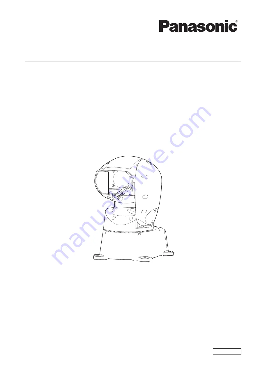
AW-HR140PJ
Model No.
AW-HR140EJ
Operating Instruction
HD Integrated Camera
Before operating this product, please read the instructions carefully and save this manual for future use.
Please carefully read the “Read this first!” (pages 2 to 4) of this Manual before use.