


VQTB0275-6
FJ1107MS8022 -FJ
Printed in Japan
ENGLISH
Before operating this product, please read the instructions carefully and save this manual for future use.
Operating Instructions
Model No.
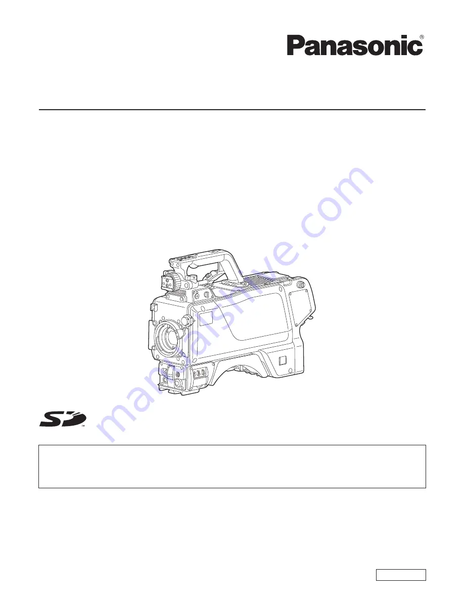
AK-HC3500E
Model No.
AK-HC3500ES
Multi-Format Camera
Die Bedienungsanleitung in Deutsch ist als PDF-Datei in der CD-ROM enthalten.
Le mode d’emploi en français est fourni sous forme de fichier PDF sur le CD-ROM.
Le istruzioni per l’uso in italiano sono contenute in un file PDF sul CD-ROM.
Las instrucciones de funcionamiento en español se encuentran en un archivo PDF del CD-ROM.
Документ Инструкция по эксплуатации на русском языке находится в виде PDF-файла на диске CD-ROM.


