background image

Operating Instructions

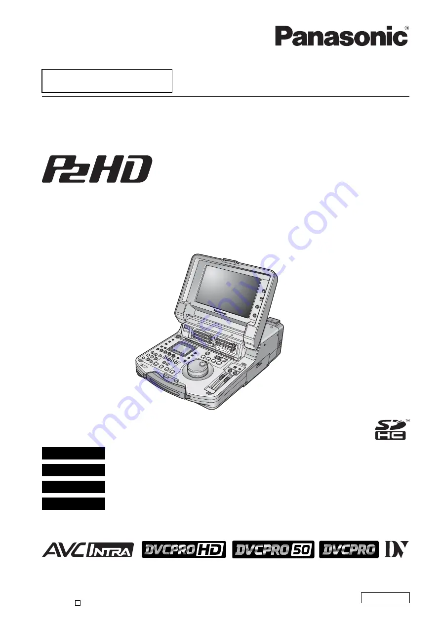
Memory Card Portable Recorder/Player

Model No. 

AJ-HPM110P

Model No. 

AJ-HPM110E

VQT1Q19

ENGLISH

Printed in Japan

S1207T0 -P 

D

Before operating this product, please read the instructions carefully and save this manual for future use.
• AVC-Intra capability is available when the optional AVC-Intra Codec board AJ-YBX200G is installed to the unit. 

 This product is eligible for the P2HD 5 Year 

Warranty Repair Program. For details, 
see page 12.

DEUTSCH

Für Erlauterungen in Deutsch, konsultieren Sie bitte die mitgelieferte CD-ROM.

FRANÇAIS

Pour des explications en français, veuillez vous reporter au CD-ROM fourni.

ITALIANO

Per le istruzioni in italiano, vedere il CD-ROM in dotazione.

ESPAÑOL

Para la explicación en español, consulte el CD-ROM uministrado.

Summary of Contents for AJHPM110E - MEMORY CARD PORTABLE...

Page 1: ...able when the optional AVC Intra Codec board AJ YBX200G is installed to the unit This product is eligible for the P2HD 5 Year Warranty Repair Program For details see page 12 DEUTSCH Für Erlauterungen in Deutsch konsultieren Sie bitte die mitgelieferte CD ROM FRANÇAIS Pour des explications en français veuillez vous reporter au CD ROM fourni ITALIANO Per le istruzioni in italiano vedere il CD ROM in...

Page 2: ...OT EXPOSE THIS EQUIPMENT TO RAIN OR MOISTURE TO REDUCE THE RISK OF FIRE OR SHOCK HAZARD KEEP THIS EQUIPMENT AWAY FROM ALL LIQUIDS USE AND STORE ONLY IN LOCATIONS WHICH ARE NOT EXPOSED TO THE RISK OF DRIPPING OR SPLASHING LIQUIDS AND DO NOT PLACE ANY LIQUID CONTAINERS ON TOP OF THE EQUIPMENT CAUTION In order to maintain adequate ventilation do not install or place this unit in a bookcase built in c...

Page 3: ...with the cart stand tripod bracket or table specified by the manufacturer or sold with the apparatus When a cart is used use caution when moving the cart apparatus combination to avoid injury from tip over 13 Unplug this apparatus during lightning storms or when unused for long periods of time 14 Refer all servicing to qualified service personnel Servicing is required when the apparatus has been d...

Page 4: ...nerates uses and can radiate radio frequency energy and if not installed and used in accordance with the instructions may cause harmful interference to radio communications However there is no guarantee that interference will not occur in a particular installation If this equipment does cause harmful interference to radio or television reception which can be determined by turning the equipment off...

Page 5: ...nience A 13 amp fuse is fitted in this plug Should the fuse need to be replaced please ensure that the replacement fuse has a rating of 13 amps and that it is approved by ASTA or BSI to BS1362 Check for the ASTA mark or the BSI mark on the body of the fuse If the plug contains a removable fuse cover you must ensure that it is refitted when the fuse is replaced If you lose the fuse cover the plug m...

Page 6: ...E THE RISK OF FIRE OR SHOCK HAZARD REFER MOUNTING OF THE OPTIONAL INTERFACE BOARDS TO QUALIFIED SERVICE PERSONNEL CAUTION In order to maintain adequate ventilation do not install or place this unit in a bookcase built in cabinet or any other confined space To prevent risk of electric shock or fire hazard due to overheating ensure that curtains and any other materials do not obstruct the ventilatio...

Page 7: ...n 35 Removing P2 Cards 36 Preventing Accidental Deletion 37 Connections 38 Example of connections in 23 98 24 29 97 25 Hz mode 38 Example of connections for remote control 38 Recording From a Variable Frame Rate Camera 39 Recording HD SDI output signals from a variable frame rate camera as 720 23 98p 39 Recording HD SDI signals output by an HD camera as 1080 23 98p requires optional accessories 40...

Page 8: ...ist Operations 70 Stop Mode Setup 73 Creating Play Lists 74 Preparing New Play Lists 74 Audio Channel Replacement During Editing 75 Registering Events for Selected Clips 75 Registering Events From Video 76 Importing and Adding to Existing Play List Files 77 Saving Play Lists 78 Naming Play Lists 78 Saving a Play List to a P2 Card 78 Editing Play Lists 80 Opening an Existing Play List File 80 Chang...

Page 9: ...onnectors 103 Using the Unit as a USB Host 103 Using the Unit as a USB Device 103 Connecting a PC to This Unit 104 Switching to USB Device Mode 104 Using This Unit With a Hard Disk 105 Supported Hard Disks 105 Switching to USB Host Mode 106 Formatting Hard Disks 106 Exporting to a Hard Disk in Card Units 107 Displaying Hard Disk Information Explorer Screen 108 Displaying Clip Thumbnails on a Hard ...

Page 10: ...put and Output Formats 147 Audio V Fade Function 149 Audio Recording Channels Selection 150 Audio Recording Channels 150 For Long and Trouble Free Operation Condensation 151 Maintenance 151 Error Messages 152 WARNING information display 153 HOURS METER information display 159 List of Shortcuts 160 Updating the Firmware in This Unit 162 Handling P2 Card Recording 163 Specifications 164 Menu index 1...

Page 11: ...e image displayed Wiping or rubbing the LCD screen with a rough cloth may damage it Leaving an unchanging image on the screen for a long period of time may create a temporary afterimage burn in LCD response and brightness vary with ambient temperature In a high temperature and high humidity location the LCD panel characteristics may change and result in uneven image quality SDHC logo is a trademar...

Page 12: ...mber of hours the device has been used 1st year 2nd year 3rd year 4th year 5th year 5 P2HD device 2 Basic warranty 3 Extended warranty repair 4 Purchase P2 product Register online within 1 month Registration Notice e mail sent Details about user registration and the extended warranty http panasonic biz sav pass_e Free 5 years of Warranty Repairs Customers who register as users on the website will ...

Page 13: ...pull the top of the lever to wards you to release the lock 2 Free the bottom of the lever Then hold the top panel and raise it to open NOTE Do not expose the lever to excessive force 1 Make sure the EJECT button is folded downwards If not folded fold the EJECT button to the right and set the card lock to on 2 Close the top panel and engage the bottom of the le ver with the receptacle in the lower ...

Page 14: ...lay back audio and video in the compressed DVCPRO HD DVCPRO50 DVCPRO DV and AVC Intra option formats on six P2 cards allows you to use the unit like a conventional editing VTR player The AJ HPM110 comes with the following features MEMO A memory card with the P2 logo for example the separately sold AJ P2C032RG is referred to as a P2 card in this manual T C R 0 0 0 1 2 3 0 1 E V 9 9 P S T O P ...

Page 15: ...he unit provides support for native recording a mode that records only active frames This provides longer recording time when a VariCam AJ HPX2000 2100 or AJ HPX3000 is connected to the HD SDI IN connector Variable frame rate VFR recording becomes possible by connecting a VariCam Native recording defined Native recording extracts only the active frames during 1080i AVC Intra requires optional boar...

Page 16: ...possible to move the audio IN point forward or backward relative to the video IN point Voice over Separately recorded audio data can replace an audio segment on one or two channels during playback AV overwrite editing This feature allows you to overwrite edit and play back any audio and video segment for 2 channels on the play list Time code Player function for editing provided This unit has a bui...

Page 17: ...evel meter indicate which signal is selected Audio and Video Controller PC CONTROL REMOTE LOCAL UNITY 4 2 2 4 UNITY 3 1 1 3 PB CH 30 10 0 10 20 2 4 CH 1 3 Headphones connector 1 2 18 19 20 22 24 21 23 15 16 17 14 12 13 11 10 9 8 7 3 4 5 6 FULL mode Selects the standard scale to 0 dB range FINE mode Selects a scale divided into 0 5 dB increments indicates reference level as set in setup menu on a s...

Page 18: ...n the LCD monitor and select the desired mode For details refer to Using USB Connectors page 103 12 CONTROL switch Use this switch to enable remote control of this unit via the 9 pin REMOTE 13 FF NEXT buttons Press to fast forward Select the speed in setup menu No 102 FF REW MAX In the playback mode hold down the SHIFT button and press the FF button to move to the beginning of the next clip During...

Page 19: ... seconds before the IN point continuing to 1 second beyond the OUT point an event at the pointer position The overwrite edit mode permits preview of unfinalized events To play back the clip at the cursor location in the thumbnail screen hold down the SHIFT button and press this button 20 TCG switch 21 COUNTER button Press to switch the counter display of the LCD panel Each press of this button cha...

Page 20: ...r a text memo In the thumbnail screen press this button to add a text memo at the start of a clip For details refer to Attaching Text Memos page 50 MARKER In the thumbnail screen while pressing the SHIFT button press this button to turn marker display of the clip at the pointer position on and off For details refer to Attaching Shot Marks page 51 ...

Page 21: ...evious screen The THUMBNAIL button goes out 3 Cursor buttons The four outer buttons are cursor buttons and the center button is the SET button Use them to move the cursor in menus thumbnails events etc to select items 4 EXIT CANCEL PF button GUI Operations PC CONTROL REMOTE LOCAL UNITY 4 2 2 4 UNITY 3 1 1 3 PB CH 30 10 0 10 20 2 4 CH 1 3 1 2 3 4 5 6 15 16 14 13 12 7 8 9 10 11 When the PLAY LIST TH...

Page 22: ... play lists Pressing the IN OUT or SPLIT button simultaneous with this button while registering an event the PLAY LIST and EVENT buttons are on allows you to set the IN OUT and SPLIT points Pressing the SHIFT button simultaneous with this button in the play list mode allows you to add a clip selected from a thumbnail display to the play list Press this button after the PF button when the THUMBNAIL...

Page 23: ...humbnails are displayed to delete a selected clip In the play list hold down the SHIFT button and press this button to delete a selected event For details refer to Using Play List page 67 The DELETE button allows you to perform on screen keyboard and file delete operations 14 SPLIT PROP button Press the ENTRY button and this button simultaneously in the play list register mode to register an event...

Page 24: ... in firmly Do not use the EJECT button when a P2 card access LED flashes orange For details refer to P2 Card Access LEDs and P2 Card Status page 35 6 Stereo speakers Outputs the audio monitor sound 7 LEVEL control Adjusts the sound volume of the internal speaker and headphones 8 BRIGHTNESS control Adjusts the brightness of the LCD monitor However it cannot adjust the brightness of time codes and o...

Page 25: ...dicator goes off 5 INPUT SELECT display Indicates selected VIDEO and AUDIO status Except for analog audio signals the indicator flashes when there is no input for the selected signal When SDI input is selected this display flashes if the input signal is not compatible with the system format 6 U lamp In the EE mode this lamp lights when an input signal contains UMID information Lights during playba...

Page 26: ...EE 1394 connector No input or output is available via the IEEE1394 connector when something other than 59 94 or 50 is selected in setup menu No 25 SYSTEM FREQ 3 ANALOG AUDIO OUT connectors Output analog audio signals 4 ANALOG AUDIO IN connectors impedance switches CH2 input switches Analog audio input connectors The input impedance of CH1 2 to CH3 4 can be switched The LINE MIC and 48V switches ma...

Page 27: ...E OUT connector does not output a time code when 23 98 24 29 97 59 23 60 24 25 or 60 25 is set in setup menu No 25 SYSTEM FREQ 10 TIME CODE IN connector Use to record an external time code onto P2 cards NOTE The time code from the TIMECODE IN connector cannot be input when 23 98 24 29 97 59 23 60 24 25 or 60 25 is set in setup menu No 25 SYSTEM FREQ 11 REF VIDEO IN connectors Input connectors for ...

Page 28: ... the power off and back on again AV signals may be disrupted when connected devices are turned on and off or when the interface cable is connected or disconnected It may take the system a few seconds to stabilize after switching input signals or changing modes Start recording after the system has stabilized The following applies to recordings made via the IEEE 1394 digital interface as well as to ...

Page 29: ...irst may damage it by the static electricity generated AVC Intra 50 and AVC Intra 100 optional recording and playback do not support input output via the IEEE 1394 connector No input or output is available via the IEEE1394 connector when something other than 59 94 or 50 is selected in setup menu No 25 SYSTEM FREQ IEEE1394 connector IEEE1394 cable plug This way IEEE1394 connector IEEE1394 cable plu...

Page 30: ...rge scale memory cards with capacities above 2 GB To format an SD card on a PC use the following software that can be downloaded from the support sites listed below This unit supports the following SD and SDHC memory card capacities SD 8 MB to 2 GB 8 MB 16 MB 32 MB 64 MB 128 MB 256 MB 512 MB 1 GB 2 GB SDHC 4 GB to 16 GB 4 GB 8 GB 16 GB For the latest information not available in the Operating Inst...

Page 31: ... P S T O P T C R 0 0 0 0 0 0 0 0 E V 0 1 P S T O P T C R 0 0 0 1 2 3 0 1 E V 9 9 S T O P T C R 0 0 0 0 2 0 2 9 P L A Y T C R 0 0 0 0 2 0 2 9 R P L A Y THUMBNAIL PLAY LIST EVENT Off On Blinking THUMBNAIL PLAY LIST Zoom in and zoom out the timeline THUMBNAIL Stop STOP INSERT upon OVERWRITE EVENT Playback PB PLAY STILL FF REW PLAY LIST INSERT EVENT Press IN OUT SPLIT ENTRY to register or edit an even...

Page 32: ...nu items NOTE Press the and buttons to move the cursor up and down Press a to open a submenu Press b or the EXIT button to return to a higher level 3 Press the SET button NOTE Some menu items may display a confirmation screen Use the cursor buttons to select a process and press the SET button 4 Press the MENU button to end processing NOTE Some menu items when selected will automatically return you...

Page 33: ...he Full Keyboard Key Function Shortcut keys BS Deletes one character SHIFT INS Caps Toggles between upper and lower case GO TO OK Saves made entries and closes the on screen keyboard ENTRY EXIT Cancels made entries and closes the on screen keyboard EXIT Moves the cursor to the first character SHIFT REW Moves the cursor 1 character space back Moves the cursor 1 character space forward Moves the cur...

Page 34: ... to Control Reference Guide page 17 NOTE The P2 card access LED for a slot where a P2 card is inserted during playback of a previously inserted card will remain off and the second P2 card is not recognized The second P2 card is recognized when playback ends A P2 card inserted in another slot during recording of a previously inserted card will cause the P2 card access LED to flash and the card will...

Page 35: ... and writing are possible Orange light Reading and writing are possible The card is selected for recording including loop recording Flashes orange Reading and writing are possible NOTE Do not turn the unit off or remove a P2 card during recording or when the LED flashes orange Flashes rapidly in orange P2 card is being recognized Flashes green The P2 card has no remaining memory capacity Available...

Page 36: ...C is not available during AUTO CAPTURE when an external device is remote controlled LOOP REC is not available in VFR mode Use one of the following two methods Set the unit POWER switch to OFF Set the menu option LOOP REC MODE to OFF NOTE Do not remove P2 cards during access or during recognition directly after insertion when the P2 card access LED flashes orange 1 Press the STOP button When the P2...

Page 37: ... or other access operation will not take effect until after these access operations playback recording etc complete For the latest information not available in the Operating Instructions of P2 cards and SD memory cards visit the P2 support desk at the following Web sites For English https eww pavc panasonic co jp pro av Preventing Accidental Deletion For the latest information on P2 cards and SD m...

Page 38: ...NTROL switch on the front panel of the external device to REMOTE Set the CONTROL switch on the front panel of this unit to LOCAL Example of connections in 23 98 24 29 97 25 Hz mode CH 1 CH 2 CH 3 CH 4 CH 1 CH 2 CH 3 CH 4 CH 5 CUE L R OUT AC IN SIGNAL GND IN PUSH PUSH PUSH PUSH PUSH PUSH PUSH PUSH OUTPUT H C H C H C H C INPUT H C H C H C H C HD HD REMOTE IN 75 ON OFF 1 2 3 SUPER SUPER IN IN OUT HD ...

Page 39: ... camera HD SDI output NOTE Set setup menu No 155 AUTO REC to TYPE1 and set the CONTROL switch to REMOTE The unit will then automatically start and stop recording as the REC and STOP buttons are pressed on the camera SDI is output in the 1080 23 98 PsF video format Analog video and IEEE1394 are not output The TIME CODE OUT connector does not output a time code and no time code can be input to the T...

Page 40: ...it to REC PAUSE mode 4 To start recording press the STILL PAUSE button while viewing the video output from the camera HD SDI output NOTE Setup menu No 155 AUTO REC to TYPE2 and set the CONTROL switch to REMOTE The unit will then automatically start and stop recording as the REC and STOP buttons are pressed on the camera SDI is output in the 1080 23 98 PsF video format Analog video and IEEE1394 are...

Page 41: ...100 SEARCH ENA so that the unit will not engage the search mode unless you press the STILL PAUSE button 1 Press the search dial to release it This engages the shuttle mode When the power has just been turned on turn the search dial to its center position 2 Press the STILL PAUSE button 3 Turn the search dial The playback picture speed changes from 0 to 16 depending on dial position Use setup menu N...

Page 42: ...h thumbnail which is the first frame of each clip represents that clip These thumbnails allow you check and also perform the following clip management operations Play back copy delete and repair clips Insert text memos in clips Check and delete text memos Display and delete markers Format P2 cards Show clip property Show P2 card status NOTE Thumbnails are generated from part of the captured video ...

Page 43: ... Indicates that a clip contains a proxy attached using the AJ SPX800 AJ HPX2000 2100 AJ HPX3000 or other camera This unit cannot record proxies 11 Text memo indicator Indicates a clip that contains text memo data 12 Edit copy indicator Indicates an edit copied clip 13 Wide indicator Indicates a clip recorded in the 16 9 aspect ratio This is not indicated for an HD format clip 14 Incomplete clip in...

Page 44: ...ultiple P2 cards the numbers of all the slots housing cards that contain the clip are indicated NOTE The pink frame indicates either of the following conditions for an inserted P2 card RUN DOWN CARD The card has been overwritten the maximum number of times DIR ENTRY NG CARD Directory structure does not conform to standard specifications gray Gray indicates that the USB host mode is not engaged or ...

Page 45: ...umbnail Display Switching the Type of Information That is Displayed 2 1 4 3 ALL CLIP Show all clips SAME FORMAT CLIPS Show clips in the same format as the system NOTE When 23 98 24 29 97 59 23 60 24 25 or 60 25 is selected in setup menu No 25 SYSTEM FREQ only clips in a format that can be recorded appear SELECTED CLIPS Show clips selected using the SET button MARKED CLIPS Show clips to which shot ...

Page 46: ...Functions page 43 TC Time code UB User bit TIME Time of recording DATE Date of recording DATE TIME Date and time of recording USER CLIP NAME The first fifteen characters English display mode in the user clip name DATE FORMAT Select the format for indicating the time Y M D Year month day M D Y Month day year D M Y Day month year NOTE This setting is reflected in the date of recording shown in the c...

Page 47: ...he text memo and move the cursor to the thumbnail you want to edit 4 Press the MENU button 5 Use the cursor buttons to choose OPERATION EXCH THUMBNAIL and press the SET button 6 Select YES and press the SET button The Menu closes and the thumbnail reflects the changes that have been made NOTE The Thumbnail field in the clip information display shows the change in thumbnail location number of frame...

Page 48: ...SET button A blue frame appears on the clip selected with the cursor to indicate that it is selected NOTE Repeat steps 1 and 2 to select multiple clips After selecting a clip move the cursor to another clip hold down the SHIFT button and press the SET button to select another clip This method allows you to select both clips 1 Place the cursor on a selected clip and press the SET button again This ...

Page 49: ...playback Pressing the STOP button during clip playback stops playback and the thumbnail screen appears When playback stops the cursor moves to the clip played prior to stopping Video and audio playback may be disrupted between clips of different formats DVCPRO HD DVCPRO50 DVCPRO DV AVC Intra50 AVC Intra100 This is normal and not indicative of a malfunction Pressing the THUMBNAIL button to close th...

Page 50: ... not a malfunction Text memos are not recorded during LOOP REC or VFR ON recording 1 Press the THUMBNAIL button The Thumbnail Screen appears on the LCD monitor 2 Press the thumbnail menu button and choose THUMBNAIL TEXT MEMO CLIPS from the thumbnail menu The thumbnails of clips with text memos appear at the top of the LCD monitor Information on the selected clip text memo appears in the lower half...

Page 51: ...ening the text memo display from the thumbnail screen allows you to delete text memos 1 Open the text memo display from the thumbnail screen 2 Use the cursor buttons to move to the thumbnail for which you want to delete the text memo and press the SET button The cursor moves to the row below 3 Select the thumbnail for witch you want to delete the text memo and select DELETE from the menu 4 Select ...

Page 52: ...plete copy at the destination is deleted OVER WRITE appears when an attempt is made to place a copy having the same GLOBAL CLIP ID at a destination already containing an identical item Select YES to overwrite or NO to cancel copying and then press the SET button 6 Press the SET button when the completion message appears 7 Press the MENU button to end processing NOTE No copying is performed when an...

Page 53: ... Use the cursor buttons to choose OPERATION DELETE 5 Select YES and press the SET button This deletes all selected clips 6 Press the MENU button to end processing NOTE Instead of steps 3 to 4 you can also hold down SHIFT and press the INSERT button to delete a clip To interrupt deleting press the SHIFT and EXIT buttons or the SET button to cancel the operation Partially deleted clips cannot be res...

Page 54: ...re the original clip NOTE Incomplete clips occur under the following conditions When the individual clip segments on each P2 card that make up the clip are copied separately When the clip segments on each card that make up a clip recorded on multiple cards are separately copied to a hard disk drive and then copied back to a P2 card When a 5 minute or longer DVCPRO HD clip 10 minute or longer DVCPR...

Page 55: ...en the P2 card where the clip resides is write protected NOTE Voice memo Indicator Indicates that a voice memo has been attached to a clip This indicator appears only in the clip property mode This unit cannot record and play back voice memos 4 Clip information The following information appears 5 Clip metadata This area shows more detailed information on a clip 5 Browse the clip metadata as necess...

Page 56: ...ncludes a GLOBAL CLIP ID VIDEO Video signal system FRAME RATE PULL DOWN ASPECT RATIO AUDIO Audio channel system and other information SAMPLING RATE BITS PER SAMPLE ACCESS The date of the last update and other information CREATOR CREATION DATE LAST UPDATE DATE LAST UPDATE PERSON DEVICE Serial number of recording equipment and other information MANUFACTURER SERIAL NUMBER MODEL NAME SHOOT Date when r...

Page 57: ...adata display reappears Select EXIT to cancel the entry and return to the previous display NOTE To delete latitude and longitude enter a blank for altitude They cannot be deleted separately Note that the metadata of a clip marked cannot be revised Insert the P2 card with the remainder of the clip Metadata to which a 100 character or larger memo has been attached cannot be revised ...

Page 58: ...metadata upload file and write it to an SD memory card NOTE Use the latest version of the P2 viewer For details on how to create a metadata upload file refer to the help function in P2 viewer For details on SD memory cards refer to the NOTE on page 162 Make the required settings to enable this unit to read the metadata upload file Set the method for recording the USER CLIP NAME 1 Open the thumbnai...

Page 59: ...ding and a new clip is generated To reset the COUNT value Use the following procedure to reset the COUNT value 1 Open the thumbnail screen 2 Press the MENU button 3 Use the cursor buttons to choose META DATA PROPERTY USER CLIP NAME and press the SET button 4 Use the cursor buttons to select COUNT RESET and press the SET button The COUNT value is reset to 1 5 Press the MENU or EXIT button to end pr...

Page 60: ... of the metadata upload file on the SD memory card appears NOTE When the file name is displayed use the right cursor button to show the metadata name Use the left cursor button to show the file name 5 Use the cursor buttons to select the file to load and press the SET button 6 Select YES and press the SET button The file is now loaded 7 Press the MENU button to end processing Use the following ste...

Page 61: ...ion screen Use the following procedure to delete metadata stored in this unit 1 Open the thumbnail screen 2 Press the MENU button 3 Use the cursor buttons to select META DATA INITIALIZE and press the SET button 4 Select YES in the confirmation screen and press the SET button This deletes the metadata 5 Press the MENU button to end processing This procedure attaches the loaded metadata to clip that...

Page 62: ...s setting records the loaded metadata simultaneous with video recording The USER CLIP NAME is attached to metadata as specified by the recording method 5 Press the MENU button to end setup 6 Record video on this unit NOTE When OFF is selected in step 4 no metadata is attached to the clip ...

Page 63: ...the P2 card slot containing the card to format and press the SET button 4 Select YES and press the SET button The card is now formatted NOTE To cancel formatting select NO and press the SET button 5 Press the SET button when the completion message appears NOTE Repeat the procedures in steps 3 to 5 to format P2 cards in other P2 card slots or SD memory cards 6 Press the MENU button to end processin...

Page 64: ...hould appear in the P2 card information 1 Open the thumbnail screen 2 Press the MENU button 3 Use the cursor buttons to choose PROPERTY PROPERTY SETUP P2 CARD CAP 4 Use the cursor buttons to select an item and press the SET button MEMO An underlined setting indicates a factory preset value 5 Press the MENU button to end processing Selecting Information to Display REMAIN Remaining capacity indicati...

Page 65: ...or memory used total memory Indicates P2 card remaining free memory or memory used total memory in time left in minutes Fractions of a minute are rounded off on the display so that the sum total of the remaining memory available for recording on each P2 card may not tally with the figure for the total memory 4 Slot remaining memory or memory used total The figure obtained by totaling the remaining...

Page 66: ... when the following P2 cards are inserted RUN DOWN CARD The card has been overwritten the maximum number of times DIR ENTRY NG CARD Directory structure does not conform to standard specifications Use Detailed P2 Card Status for more information 4 Press the EXIT button to end processing ...

Page 67: ...een Play list can also be stored on a P2 card To save the voice over audio data to the same P2 card as the play list first save the play list to a P2 card The processing activities entered on each line in the play list screen to run the play list are called events During play list playback only formats set as edit formats can be played and registered Do not add a 24PN clip created in non linear ed...

Page 68: ...o zoom in right and to zoom out left 5 Record mode 6 System format Refer to Thumbnail Screen Names and Functions page 43 Play List Screen Names and Functions 2 4 13 14 3 1 10 11 16 8 7 6 15 5 9 12 18 17 19 PLAYLIST Event list EVENT PROPERTY Detailed event information P2 USED Media information amount of space used P2 REMAIN Media information amount of free space NO Event serial number TOTAL Total t...

Page 69: ...ly set insert mode selected by the SETTING INSERT MODE menu 14 Overwrite track indication Indicates INPUT menu settings in overwrite edit mode 15 Source IN OUT points Indicates source player IN point OUT point TC and thumbnails Items that are not registered are hidden 16 Duration indication Shows the length of events for which overwrite edit is in unfinalized status 17 Playback location Indicates ...

Page 70: ...tton performs the same function as EXIT in a menu display CANCEL button To cancel all selected events and release items in unfinalized status in the overwrite edit mode hold down the SHIFT button and press the EXIT button 4 b a Cursor buttons In the play list press this button to move the play list and time line pointer location Use the right and left buttons to move the timeline horizontally Use ...

Page 71: ...egister edit mode when the EVENT button is on hold down the SPLIT button and press the ENTRY button The location where the button was pressed will become the audio split IN point 8 CLIP LIST button Use this button to import a clip selected in the thumbnail screen into the play list Select a clip in a thumbnail display multiple clips can be selected and switch to the play list display Hold down the...

Page 72: ...EVENT button blinks to locate the IN OUT and SPLIT points During normal playback still playback and other playback operations hold down the IN OUT or SPLIT button and press the GO TO button to move to the IN OUT or SPLIT point and resume playback from there In the overwrite edit mode the playback location in yellow can be moved to the IN or OUT point of an event at the cursor location in the play ...

Page 73: ...the recommended setting during playback of a play list from an external controller or other device connected to the remote control connector Stop Mode Setup RETURN A return is made to the play list screen when the STOP is pressed or when an automatic stop occurs at the start or end of all events The cursor position moves to the event where the button was pressed STAY A return to the play list scre...

Page 74: ...e 122 1 The following setup menu determines voice over settings only when an AJ YBX200G AVC Intra codec board optional board is installed 792 A DUB CH Refer to page 137 793 A DUB PB MIX Refer to page 137 2 Open the play list screen 3 Press the MENU button 4 Use the cursor buttons to choose SETTING INSERT MODE and press the SET button This selects INSERT and engages the insert edit mode 5 Use the c...

Page 75: ...uttons to choose OPERATION EDIT AUDIO CH and press the SET button Then select YES to switch channel locations NOTE A channel switch is indicated by EDITED in the A CH field The status after the switch also shows up in the event property For details refer to Viewing Event Information page 98 Use the following procedure to add selected clips to the play list This operation registers the start of a c...

Page 76: ...tton engages the event edit mode regardless of the insert mode setting For details refer to Changing Event IN and OUT Points page 81 5 Register an IN point Use the operation buttons or search dial to look for a location to start an event Then hold down the IN button and press the ENTRY button 6 Register an OUT point Use the operation buttons or search dial to look for a location to end an event Th...

Page 77: ...f the P2 card slot containing the play list you want to import and press the SET button 6 Select a file in the file import screen and press the SET button The specified play list event is added at the cursor location NOTE You cannot import a play list file whose format differs from the format of the current play list If the number of selected events exceeds 100 the events that exceed the limit wil...

Page 78: ... NAME NOTE The file name must be saved using FILE SAVE or FILE SAVE AS Use the steps below to save a play list stored by the unit in the play list area of memory to a P2 card 1 Open the play list screen 2 Press the MENU button 3 Use the cursor buttons to choose FILE SAVE AS 4 Use the cursor buttons to select the number of the P2 card slot that will store the file and press the SET button 5 Check t...

Page 79: ...ally generated and cannot be changed Changing the filename on a PC will make it impossible to load Updated play list files cannot be loaded by older versions or devices Store old versions of the play list in the unit before using them They cannot be edited in the form they are loaded ...

Page 80: ... or SD CARD containing the play list you want to import and press the SET button 5 Select the file to import in the file import screen and press the SET button 6 Select YES in the confirmation screen and press the SET button The play list is now loaded NOTE If a play list file that contains more than 100 events is opened the event data exceeding 100 is not imported and the play list becomed a read...

Page 81: ... will show that the IN point of that clip has automatically been changed and registered at the beginning of the clip An event with a voice over cannot be modified Delete the voice over before modifying the event The changed content will be neglected if the unit is turned off during change of an event from video You can change IN and OUT points for events in frame increments in 4 frame increments a...

Page 82: ...lay list screen 2 Select the event you want to move and press the SET button The event is selected and appears in blue This procedure can be repeated as necessary to select multiple events NOTE To quickly select successive lines Hold down the SHIFT button and press the SET button MULTI SEL to select all events from the previous time the SET button was pressed and up to the cursor location where th...

Page 83: ...ation screen and press the SET button This deletes all selected events NOTE You can also delete a selected event in step 3 by holding down the SHIFT button and pressing the INSERT button DELETE It is not possible to delete only the event if that event contains an EXTRA track Delete the EXTRA track before deleting the event or delete the event and the EXTRA track If there is an EXTRA event that spa...

Page 84: ...S the file can subsequently be saved using the following procedure Use SAVE AS for the first save operation 1 Open the play list screen 2 Press the MENU button 3 Use the cursor buttons to choose FILE SAVE 4 Press the SET button 5 Select YES in the confirmation screen and press the SET button This saves the play list Saving Events ...

Page 85: ...st appears in yellow This procedure can be repeated as necessary to select multiple play lists 6 Press the SHIFT and INSERT buttons simultaneously select YES and press the SET button This deletes the play list NOTE To quickly select successive files Hold down the SHIFT button and press the SET button MULTI SEL to select all files from the first file selected with the SET button to the file at the ...

Page 86: ... insert edit mode is the default setting Activating auto entry will automatically register the OUT point R OUT registered in the play list as the IN point R IN of the next event 1 Press the MENU button and use the cursor buttons to choose SETTING AUTO ENTRY 2 Press the SET button choose ON and press the SET button Use the overwrite edit mode with REPLACE TC enabled If REPLACE TC is disabled the ti...

Page 87: ...t audio on the EXTRA track NOTE Pressing the A DUB button after selecting multiple events simultaneously copies the events on the EXTRA track Use the IN and OUT buttons to select the location R IN R OUT for inserting video from the play list and the location P IN P OUT for inserting the source video As soon as three IN and OUT points are defined the remaining point is automatically determined and ...

Page 88: ...ll show the total time TOTAL DURATION for all events Holding down the IN OUT button and pressing the RESET button will clear the registered point Pressing the IN OUT ENTRY buttons in the play list will register the current playback location yellow to R IN R OUT Pressing the IN OUT GOTO buttons in the play list will move the playback location to the IN OUT point of the event at the cursor The time ...

Page 89: ...ring a preview 2 Use the playback volume to adjust playback level during preview The playback level is fixed at the level set during preview Review and play list playback plays back events at the imported sound volume NOTE When there are multiple events all events are played back at the same sound volume The same sound volume is used in an event and cannot be changed Use the steps below to finaliz...

Page 90: ...ll function 1 Move the cursor to the event you want to recall 2 Press the REC button 3 Register the time code at the R IN R OUT and P IN points of the selected event to clear the finalized status 4 Revise the IN and OUT points as necessary adjust recording level and set audio channels 5 After revising press the REC button to register the event Recalling Events ...

Page 91: ... IN point audio IN point split Note that audio channels cannot be selected in this procedure This function is performed on all channels together Play list example 1 Play list example 2 6 A 6 6 6 6 4 4 4 4 5 7 7 7 7 5 5 5 New play list event Preceding audio 6 A 7 7 5 5 4 4 4 4 5 6 6 6 7 7 5 6 New play list event Silent segment Delayed audio ...

Page 92: ...own the SPLIT button and press the ENTRY button 6 Register an OUT point Use the operation buttons or search dial to look for a location to end an event Then hold down the OUT button and press the ENTRY button 7 Press the EVENT button to end registration The INSERT button will also terminate registration NOTE In the split display indicates forward while indicates reverse direction A split can be re...

Page 93: ...ition can take place even when the IN point is changed before step 4 or the OUT point is changed after step 4 You can change audio split points in frame increments in 4 frame increments at 24PN 1 Open the play list screen 2 Use the cursor buttons to select the event where you want to change an audio split point 3 Change the audio split point Hold down the SPLIT button and press the TRIM button or ...

Page 94: ...ed Use the following procedure to cancel an audio split setting 1 Open the play list screen 2 Use the cursor buttons to select the event where you want to cancel the split setting 3 Hold down the SHIFT button and press the RESET button This cancels the audio split setting NOTE Use the play list screen or the event register mode to cancel a split setting An audio split point is also cancelled by de...

Page 95: ... When mixing is selected select the channels to mix in setup subscreen The playback sound of the selected channels is mixed with A DUB CH and recorded When there are multiple A DUB CH make separate settings for each NOTE In play list playback playback level is set to UNITY fixed or registered recording level and cannot be changed However EE audio while the A DUB button is pressed and during A DUB ...

Page 96: ...is set in setup menu No 026 PLY LST FMT the audio IN and OUT points are set in 4 frame increments If the recording starts or stops at some other points the IN and OUT points are automatically corrected within the recording range 1 Open the play list screen 2 Use the cursor buttons to select the event where you want to perform a voice over 3 Press the PLAY button to start playback at a location bef...

Page 97: ...4PN in 4 frame increments 1 Open the play list screen 2 Select the event you want to change 3 Use the following procedure to change offset and duration 4 Press the ENTRY button to finalize the change NOTE Except for the ENTRY button you can also use the SET button or move the cursor with the cursor buttons to finalize a change Displaying Voice Over Events Changing the Trimming of Audio Recording L...

Page 98: ... viewing event information 1 Event information Event number IN point and OUT point thumbnails and TC value TOTAL length from the beginning of the 1st event to the end of the current event DURATION event length A SPLIT audio split length TRACK A CH Track status and audio channel status AV audio and video FADE CUT EXTRA audio splicing indication of channels inserted in channels 1 4 2 Original clip i...

Page 99: ... and press the PLAY button This plays back the clip from before the IN point preroll time is 3 s to beyond its OUT point postroll time is 1 s NOTE The preroll time and postroll time for the first and last clip are both 0 s When review stops or you press the STOP button playback stops and you return to the play list screen During review all buttons other than the STOP button are not available A rev...

Page 100: ... time code NOTE When OFF is set the time code is not replaced instead the time code of each clip is output When OFF is set go to step 7 and end setup 5 Use the cursor buttons to choose SETTING REPLACE TC START TC and press the SET button to enter the start time code The initial value of the start time code is 00 00 00 00 when replaced 6 Use the cursor buttons to choose SETTING REPLACE TC DROP FRAM...

Page 101: ...ent events that cannot be played back are indicated in red Use the STOP button to stop ongoing playback The default stop mode setting of this unit is RETURN Thus you return to the play list screen when playback is stopped by pressing the STOP button or the automatic stop function stops playback upon reaching the beginning or end of all events The cursor position then moves to the event where the S...

Page 102: ...he SET button This starts edit copy NOTE If total free space on an inserted P2 card is not sufficient to store edit copy data the message WARNING LACK OF REC CAPACITY appears and edit copy does not start Edit copying indicates its approximate progress during operation Use the SET button or the CANCEL button to cancel an ongoing edit copy operation Text memos are automatically inserted at the edit ...

Page 103: ...o P2 cards A USB 2 0 connection with a PC allows you to use P2 cards inserted in the slots on this unit as mass storage The PC then requires that a USB USB 2 0 driver be installed Use of P2 viewer which can be downloaded from the following site allows you to manipulate clips stored on a P2 card on a Windows PC https eww pavc panasonic co jp pro av NOTE For details regarding connections refer to th...

Page 104: ...n This message is replaced by a USB DEVICE CONNECT message when the connection with the PC is completed 3 Use USB device mode operations 4 Press the PC button to return to regular mode NOTE Recording and playback are not available in the USB device mode In the play list mode the PC button is not available during remote operation In the USB device mode USB is displayed on the panel and the VIDEO an...

Page 105: ...rd disk must be rebooted A hard disk is a precision instrument whose read and write functions may fail in some operating environments Please note that Panasonic accepts no liability whatsoever for data loss or other losses either direct or indirect arising from hard disk damage or other defects When data from this unit is copied to a hard disk and is managed on another PC the data can no longer be...

Page 106: ...ither 4 Press the PC button to return to regular mode The PC button will not work during card access NOTE When switching to the USB host mode You cannot switch to the play list mode from the USB mode In USB host mode the VIDEO and AUDIO INPUT SELECT indications in the display panel disappear Initialize the hard disk in a TYPE S format NOTE Formatting a hard disk deletes all data on the disk 1 Swit...

Page 107: ... HDD EXPORT 7 Select the number of the source P2 card slot and press the SET button Selecting ALL SLOT will result in a batch export of all cards 8 Select YES and press the SET button This starts exporting NOTE A progress bar appears during exporting To interrupt exporting press the SET button select YES in the cancel confirmation screen and press the SET button again The export operation will end...

Page 108: ... partition on a P2 store is indicated in gray Only information for the primary partition is displayed for a hard disk that is formatted using FAT 4 USB HOST The USB host mode indicator 5 Hard disk drive status Indicates whether or not a hard disk is connected and hard disk type NOTE To name a partition up to 20 characters choose CHANGE PARTITION NAME in the OPERATION menu in hard disk thumbnail sc...

Page 109: ...cards For details refer to Changing Thumbnail Display page 45 Hard disks formatted using FAT can handle up to 1000 clips Any clips beyond that limit cannot be opened Use the TRIM buttons to move to thumbnail displays on previous and subsequent partitions You can view a variety of metadata on clips stored on a hard disk The content is the same as that displayed by a P2 card clip property 1 Select a...

Page 110: ...n function to rebuild the clip Refer to Reconnecting Incomplete Clips page 54 A menu setting allows you to turn verification during copying on or off You can select a hard disk clip and import it to a P2 card 1 Insert the P2 card where the data will be imported to 2 Open the hard disk thumbnail screen 3 Press the MENU button 4 Use the cursor buttons to select HDD EXPLORE and press the SET button 5...

Page 111: ...g Use the following procedure to format an SD memory card inserted in an SD memory card slot 1 Open the thumbnail screen 2 Press the MENU button 3 Use the cursor buttons to select OPERATION FORMAT SD CARD 4 Select YES and press the SET button The card is now formatted NOTE To cancel formatting select NO and press the SET button 5 Press the SET button check when the completion message appears Displ...

Page 112: ...12 Using USB Connectors and SD SDHC Memory Cards Using SD SDHC Memory Cards NOTE Repeat the procedures in steps 2 to 4 to format P2 cards in other P2 card slots 6 Press the MENU button to end processing ...

Page 113: ...emotely connected device before pressing the EVENT button 1 Available when the optional AVC Intra Codec board AJ YBX200G is installed In external control mode the EVENT lamp goes on and the unit provides the following indications The LED goes on to indicate external device status Indicates the external device counter The unit is forcibly set to EE to enable reception of audio and video from the ex...

Page 114: ...om the current location can be recorded to a card 1 Enter the mode that permits control of external devices Hold down the SHIFT button and press the EVENT button when the THUMBNAIL and PLAY LIST buttons are off 2 Select the start of a section you want to capture Use the PLAY STILL or other buttons to locate the start of the section you want to capture 3 Hold down the SHIFT button and press the REC...

Page 115: ... 116 After a change the content of USER1 can be saved copied to USER2 to USER5 For details refer to Setup menu No A01 SAVE page 139 SETUP menu settings can be saved to and loaded from an SD memory card For details refer to Setup menu No A10 CARD READ page 139 A11 CARD WRITE page 140 You can specify the user setting files that will be loaded in USER1 at power up You can also decide to use the same ...

Page 116: ...tton or the button To switch to a previous item hold down the PLAY button and press the REW button or the button 4 Change set values Select the item to change hold down the STILL PAUSE button and turn the search dial or press the left b or right a button to change the setting Turn the dial clockwise or press the right a button to increment the set number and turn it counterclockwise or press the l...

Page 117: ... 119 For details on releasing the user file lock setting refer to Setup menu No A03 MENU LOCK page 139 NOTE Files can be loaded from the SD memory card even if they are locked The status after load operation depends on the setting defined by the loaded data When the menu is open you can return the content of the user setting file that appear on the screen to its factory defaults NOTE This operatio...

Page 118: ...an be returned to its factory default by pressing the RESET button 15 SYS H SD 0000 0864 1728 864 0 864 Adjusts system phase of analog composite output and SD SDI output in 37 ns steps Advances the phase Delays the phase NOTE A reset does not return this setting to its factory default An item that flashes can be returned to its factory default by pressing the RESET button 18 SCH COAR SD 0000 0001 ...

Page 119: ...and turn it back on again 2 23 98 Hz and 3 24 Hz are available only when the AJ YBX200G AVC Intra codec board optional board is installed 0000 0001 0002 0003 0004 0005 0006 0007 0008 59 94 50 23 98 24 29 97 59 23 60 24 25 60 25 For AJ HPM110E 0000 0001 0002 0003 0004 0005 0006 0007 0008 59 94 50 23 98 24 29 97 59 23 60 24 25 60 25 26 HD SYS H ADV 0000 0001 0H 90H Specifies whether or not HD output...

Page 120: ...ine NOTE These functions are not displayed when 2L is selected and TIME is set in setup menu No 006 DISPLAY SEL Total tape time is not displayed when R TTL is selected and TIME is set in setup menu No 006 DISPLAY SEL When setup menu No 041 LOOP REC is set to ON the remaining time is indicated on the second line when a setting other than OFF is selected When setup menu No 040 VFR REC is set to ON t...

Page 121: ... The 720p recording format is used Not indicated when 23 98 or 24 is selected in setup menu No 25 SYSTEM FREQ The 1080i recording format is used Not indicated when 60 24 or 60 25 is selected in setup menu No 25 SYSTEM FREQ The 720p recording format is used 0000 0001 0002 1080i 720p 480i When set to 50 Hz 0000 0001 0002 1080i 720p 576i When set to 29 97 Hz 25 Hz 59 23Hz 0000 0001 1080p 720p 024 REC...

Page 122: ...o SUPER DISP 026 PLY LST FMT When set to 59 94 Hz Specifies the format used by the play list In the DVCPRO HD format 0 Format set in setup menu No 020 SYS FORMAT and No 025 REC FMT HD 1 720 30PN when set to 59 94 Hz 720 25PN when set to 50 Hz 2 720 24PN In the AVC Intra format 0 Format set in setup menu No 020 SYS FORMAT and No 025 REC FMT HD 1 1080 30PN when set to 59 94 Hz 1080 25PN when set to ...

Page 123: ...ext time it is powered up 050 P ON GUI 0000 0001 OFF THUMB Specifies whether or not the thumbnail screen appears when the power is turned on 0 Thumbnail screen does not appear 1 Thumbnail screen appears 069 CLOCK SET Sets the internal clock NOTE Press the STOP or SET button to open the subscreen for setting the time Change the date in the subscreen and press the SET button to set the clock date To...

Page 124: ... Europe 02 30 03 00 Moscow 03 30 Teheran 04 00 Abu Dhabi 04 30 Kabul 05 00 Islamabad 05 30 Bombay 06 00 Dacca 06 30 Rangoon 07 00 Bangkok 07 30 08 00 Beijing 08 30 09 00 Tokyo 09 30 Darwin Islands 10 00 Guam 10 30 Lord Howe Island 11 00 Solomon Islands 11 30 Norfolk Islands 12 00 New Zealand 12 45 Chatham Islands 13 00 12 00 Kwajalein Atoll 11 30 11 00 Midway Islands 10 30 10 00 Hawaii 09 30 Marqu...

Page 125: ...speed 3 60 normal speed 4 100 normal speed 102 FF REW MAX 0000 0001 0002 0003 32 60 100 SEEK Sets the maximum speed of FF and REW operation 0 32 normal speed 1 60 normal speed 2 100 normal speed 3 Seek operation to start of clip NOTE When SEEK is selected FF and REW operations for FF and REW commands transferred via 9P and 1394 are performed at 100 normal speed The seek operation is available in p...

Page 126: ...play additional clips are not played back until you once stop repeat play and resume it 180 BATTERY SEL 0000 0001 0002 0003 0004 0005 0006 NiCd12 NiCd13 NiCd14 S LION I LION TYPE A TYPE B Sets the battery type 0 Settings for 1 pc 12 V battery NEAR 11 2 V END 10 6 V 1 Settings for 1 pc 13 V battery NEAR 12 0 V END 10 6 V 2 Settings for 1 pc 14 V battery NEAR 13 6 V END 10 6 V 3 Settings for 1 pc li...

Page 127: ...een TYPE1 and TYPE2 For operating details see respective operating instructions AJ HDX400E 1080 50i 1 1080 25p over 50i 1 AJ HDX900 720 59 94p TYPE1 720 23 98p over 59 94p TYPE1 720 29 97p over 59 94p TYPE1 1080 59 94i 1 1080 23 98p over 59 94i TYPE2 1080 29 97p over 59 94i 1 1080 50i 1 1080 25p over 50i 1 720 50p TYPE1 720 50p over 50p TYPE1 AG HPX500 AJ HPX2000 2100 AJ HPX3000 720 p TYPE1 2 1080...

Page 128: ...z 0000 0004 0015 7L 11L 22L 502 VITC POS 2 When set to 59 94 Hz 29 97 Hz Specifies the position where the VITC signal will be inserted NOTE You cannot select the same line as in menu No 501 VITC POS 1 This setting is available only during analog composite output and SD SDI output 0000 0008 0010 10L 18L 20L When set to 50 Hz 25 Hz 0000 0006 0015 7L 13L 22L 504 RUN MODE 0000 0001 REC FREE Specifies ...

Page 129: ...10 TCG CF FLAG 0000 0001 OFF ON Sets the TCG CF flag 0 OFF 1 ON 511 DF MODE 0000 0001 DF NDF Sets the DF or NDF mode for CTL and TCG 0 Uses drop frame mode 1 Uses non drop frame mode 512 TC OUT REF 0000 0001 VOUT TC_IN Specifies how the phase is switched for the time code output by the TIME CODE OUT connector for the external LTC input when the TC INT EXT switch is set to EXT only in EE mode 0 Syn...

Page 130: ...5PN clip formats 0 Outputs the user bits recorded in the SBC area 1 Outputs the frame rate information recorded in the VAVX area SBC Sub Code Data area This area which is separate from video and audio data area on a P2 card stores SMPTE EBU compliant time code recording dates and other information VAUX Video Auxiliary Data area An area in the video data on a P2 card that stores additional informat...

Page 131: ...t vertical outlines be emphasized in down conversion 0 0dB 1 1dB 643 OUT MODE SEL When set to 59 94 Hz 29 97 Hz Specifies the video signal output from the video output connector 0 Switches output automatically depending on current recording and playback format 1 1080 59 94i or 1080 50i 2 720 59 94p or 720 50p 3 480 59 94i or 576 50i NOTE When something other than AUTO is selected a signal that dif...

Page 132: ...in menu No 650 STYLE 658 Y LVL SD 0000 1000 1413 0 00 100 00 141 30 Adjusts the Y level of SD SDI and analog composite output to 0 dB to 3 dB NOTE This setting is available when CMPNT is set in menu No 650 STYLE 659 Pb LVL SD 0000 1000 1413 0 0 100 0 141 3 Adjusts the PB level of SD SDI and analog composite output to 0 dB to 3 dB NOTE This setting is available when CMPNT is set in menu No 650 STYL...

Page 133: ...nce signals 0 Does not clip the signal 1 Clips the signal 677 LCD ASPECT 0000 0001 0002 0003 AUTO 4 3 16 9 15 9 Specifies the aspect ratio of image displayed on the LCD panel 0 Switches aspect ratio automatically 1 Displays 480i or 576i images in the 4 3 aspect ratio Displays 1080i or 720p video in the 16 9 aspect ratio 2 Displays images in the 16 9 aspect ratio 3 Displays images in the 15 9 aspec...

Page 134: ...erated by dark areas that are about 10 IRE 70 mV or less NOTE This setting is available in DVCPRO HD 720p mode recording 690 UMID REC 0000 0001 OFF ON Specifies whether or not UMID data should be recorded 0 UMID data is not recorded 1 Recorded 691 UMID GEN 0000 0001 INT EXT Specifies the generation method of UMID information that is recorded when menu No 690 UMID REC is set to on 0 Newly created U...

Page 135: ...text GAMMA on the screen Turning the power off cancels the GAMMA setting This item has no effect during 1394 output AUDIO Item Setting Settings and brief function description FR No SUPER DISP FR No SUPER DISP 701 CH1 IN LV 0000 0001 0002 0003 4dB 0dB 3dB 20dB Specifies the standard level for audio input CH1 702 CH2 IN LV 0000 0001 0002 0003 4dB 0dB 3dB 20dB Specifies the standard level for audio i...

Page 136: ...1 and CH2 signal 5 Mixed audio input CH3 and CH4 signal 728 REC CH4 0000 0001 0002 0003 0004 0005 CH1 CH2 CH3 CH4 CH1 2 CH3 4 Specifies the input signal to be recorded on the audio CH4 0 Audio input CH1 signal 1 Audio input CH2 signal 2 Audio input CH3 signal 3 Audio input CH4 signal 4 Mixed audio input CH1 and CH2 signal 5 Mixed audio input CH3 and CH4 signal 731 PB FADE 0000 0001 AUTO CUT Specif...

Page 137: ...H1 0000 0001 0002 CH1 CH1 2 CH1 3 Specifies the playback channels that will be output via CH1 02 PB CH2 0000 0001 0002 CH2 CH1 2 CH2 4 Specifies the playback channels that will be output via CH2 03 PB CH3 0000 0001 0002 CH3 CH3 4 CH1 3 Specifies the playback channels that will be output via CH3 04 PB CH4 0000 0001 0002 CH4 CH3 4 CH2 4 Specifies the playback channels that will be output via CH4 790...

Page 138: ... over 0 Recorded sound is not output 1 Recorded sound is output DIF Item Setting Settings and brief function description FR No SUPER DISP FR No SUPER DISP 880 DIF SPEED 0000 0001 0002 S100 S200 S400 Specifies the transfer speed of digital video interface output 0 100 Mbps 1 200 Mbps 2 400 Mbps NOTE A DVCPRO HD format signal cannot be output when S100 is selected 882 DIF IN CH 0000 0063 0064 0 63 A...

Page 139: ...ears and data cannot be saved Setting available for USER1 only A02 P ON LOAD 0000 0001 0002 0003 0004 OFF USER2 USER3 USER4 USER5 Specifies which user files will be loaded into USER 1 and whether or not the USER 1 settings should be used in startup when the power is turned on 0 Operation is started with the settings of the previously set user file 1 The content of USER 2 is loaded into USER 1 2 Th...

Page 140: ...es to be written in the file menu that appears and press the SET button Files that are not written are indicated as NO FILE NO CARD is indicated when no SD memory card is inserted A11 CARD WRITE Select one of the four files on an SD memory card to write a menu setting The write function is available only to USER 1 5 SYSTEM Titles can be added to the files and the files can be edited Setting availa...

Page 141: ...loses 1 Press the MENU button select A12 CARD FORMAT from USER1 in the SETUP menu and press the SET button 2 The format confirmation screen appears Press the SET button to start formatting To cancel formatting and return to the previous screen press the EXIT button 3 A completion message appears when the format progress bar closes Up Down cursors Select text b a Right and left cursors Move cursor ...

Page 142: ... down the STILL button and turn the search dial to change the value 3 Press the LEFT b or RIGHT a button or turn the search dial to select digit to set The selected digits start flashing The setting ranges are as follows 4 Repeat steps 2 3 to change other values Pressing the RESET button resets the preset value to 0 5 When the start number is set press the SET button The time code starts to advanc...

Page 143: ...ing the time code generator to provide long term about one year operation Accuracy when no power is supplied is about 30 s per month NOTE Under the conditions listed below when the time code generator advances regardless of operation mode the backup function is enabled When the TCG switch on the front panel is set to PRESET and setup menu No 504 RUN MODE is set to FREE When the TCG switch on the f...

Page 144: ... digital input SBC area Time code on IEEE1394 digital input VAUX area HD SDI Time code on TIME CODE IN connector input 1 SVITC on input video signal 3 CMPST SD SDI VITC on input video signal 3 ON 1394 Time code on IEEE1394 digital input SBC area Time code on IEEE1394 digital input VAUX area HD SDI Time code on TIME CODE IN connector input 1 CMPST SD SDI SLTC OFF 1394 Time code on IEEE1394 digital ...

Page 145: ...splays the play position relative to the start position Recording starts from the counter value 0 00 00 00 When recording stops the counter shows the position relative to the start position NOTE When 23 98 24 59 23 or 60 24 is selected in setup menu No 25 SYSTEM FREQ there is a 1 frame delay between playback video and CTL CTL Mode 1 2 ...

Page 146: ...H POS and No 008 CHARA V POS to change the position of characters in the superimposed display Use setup menu No 006 DISPLAY SEL to indicate deck operating mode CTL Relative location from the beginning TCR Recorded time code data TCR Time code data recorded in the VAUX area UBR Recorded user bit data UBR User bit data recorded in the VAUX area TCG Time code data of the time code generator UBG User ...

Page 147: ...20 50P 576 50i 576 50i 1080 29 97PsF 29 97 1080 29 97PsF 1080 59 94i 1 720 59 94P 1 720 59 94P 1 480 59 94i 1 480 59 94i 1 1080 23 98P over 59 94i 5 59 23 1080 23 98PsF 1080 23 98PsF 23 98 1080 23 98PsF 1080 24PsF 24 1080 24PsF 1080 25PsF 25 1080 25PsF 1080 50i 1 720 50P 1 720 50P 1 576 50i 1 576 50i 1 720 59 94P 59 94 720 59 94P 720 59 94P c 1080 59 94i 1080 59 94i 480 59 94i 480 59 94i 720 50P 5...

Page 148: ... 59 94 720 59 94P 720 59 94P 720 59 94P c 1080 59 94i 1080 59 94i 480 59 94i 480 59 94i 720 50P 50 720 50P 720 50P 720 50P c 1080 50i 1080 50i 576 50i 576 50i 720 29 97P over 59 94P 6 29 97 720 59 94P 1 720 59 94P 1 1080 29 97PsF 1080 59 94i 1 480 59 94i 1 480 59 94i 1 720 23 98P over 59 94P 6 59 23 1080 23 98PsF 720 24P over 60P 6 60 24 1080 24PsF 720 25P over 50P 7 25 720 50P 1 720 50P 1 1080 25...

Page 149: ...hat has been automatically divided and recorded on an 8 GB P2 card A clip created using the edit copy function on an AJ SPD850 Settings in setup menu No 731 allow you to play back the above two clips and do the following When CUT is selected When AUTO is selected V fade processing is performed automatically between clips and events The following items are not V fade processed Clips that span multi...

Page 150: ...g Analog input SDI input Audio Recording Channels Recorded track Recorded signal CH1 CH1 input CH2 input CH1 CH2 inputs CH2 CH1 input CH2 input CH1 CH2 inputs CH3 CH3 input CH4 input CH3 CH4 inputs CH4 CH3 input CH4 input CH3 CH4 inputs CH5 No CH6 No CH7 No CH8 No Recorded track Recorded signal CH1 CH1 input CH2 input CH1 CH2 inputs CH2 CH1 input CH2 input CH1 CH2 inputs CH3 CH3 input CH4 input CH...

Page 151: ...ved from a cold location to a hot or humid location When moving the unit to locations such as these leave it standing for about 10 minutes rather than switching on the power immediately Before starting any maintenance work switch the power to off and holding the plug unplug the cord from the socket Use a soft cloth to clean the outside of this unit For stubborn dirt or stains wipe the unit with a ...

Page 152: ...NALOG COMPOSITE MONITOR OUT connector on the LCD monitor and rear panel of the unit 1 Press the DIAG button hold down the SHIFT button and press the MENU button The DIAG menu appears on the monitor screen and the message appears on the counter display 2 Press the SET button or the right or left cursor button Each press of the button changes the display between WARNING HOURS METER and UMID INFO etc...

Page 153: ...e space available Card status changed during recording Recording was attempted when the unit was BUSY VFR recording started but no active frame data was input STOP CANT REC CANNOT LOOP REC Appears in LOOP REC mode when P2 card recording is not available Meaning An attempt was made to record to a write protected disk An attempt was made to record on a card with no free space available An attempt wa...

Page 154: ...KNOWN SIG Displayed when a signal input from the 1394 interface is not a DVCPRO or DV format signal Recording is disabled 10 FAN STOP Displayed when the fan motor stops Operation continues 11 NOT 1 25M SIG Displayed when a signal input from the 1394 interface is not a DVCPRO 25 Mbps 1 normal speed transfer signal Recording is disabled 12 NOT 1 50M SIG Displayed when a signal input from the 1394 in...

Page 155: ... drop frame mode during EE or recording Normal recording will not be possible under these conditions Check signal input to the unit Set the input time code to non drop frame mode Appears when 23 98 24 59 23 60 24 or 60 25 is set in setup menu No 25 SYSTEM FREQ Operation continues 95 INVALID EMBEDDED TC Displayed while synchronizing recorded video frames to the time code of a signal input to the HD...

Page 156: ... the viewer to enter correct characters CANNOT REPAIR IN SELECTION Some of the selected clip could not be repaired NO SD CARD No SD memory card is inserted Insert an SD memory card NO COPY TO SAME CARD A clip cannot be copied to the card storing the original clip Copy the selected clip to a card that does not contain the original clip SAME CLIP IS SELECTED The selected clips contain multiple copie...

Page 157: ...mat Use a P2 card with appropriate capacity P2 CARD IS UNFORMATTED The P2 card is not formatted Use a formatted P2 card CARD IS EMPTY CANNOT COPY The P2 selected for copying is empty Copying is not performed since the card is empty VERIFICATION FAILED The compare check after copying failed Copy the data again PLEASE FORMAT P2 CARD This warning indicates that data could not be imported from a hard ...

Page 158: ... event CANNOT OPERATE AT RED EVENT Not allowed in a playback disable marked red event An illegal operation was attempted in a disabled event Use a playback enable event or insert a card with suitable clips DURATION LIMITATION The selected process cannot be performed because play list duration exceeds 24 hours Delete data to reduce the duration to less than 24 hours to process DIFFERENT SYSTEM FREQ...

Page 159: ... command was not complied to To continue operation turn the power off and then back on again STOP E 38 SYSTEM ERROR Displayed when the fan motor stops To continue operation turn the power off and then back on again STOP E 39 CONFIG ERROR Appears when an optional AVC Intra Codec board AJ YBX200G cannot be initialized This may be caused by a board malfunction Consult your supplier STOP E BA BATTERY ...

Page 160: ...REVIEW REVIEW Plays back the event at current location or 3 seconds prior to the overwrite area to 1 second after the area SHIFT ENTRY CLIP EVENT Imports the selected clip as an event SHIFT IN DISP SLOT CLIPS Toggles between thumbnail display of each individual slot and selected clip display IN TRIM Selects trimming of R IN P IN SHIFT OUT DISP ALL CLIP Changes thumbnail display to all clip display...

Page 161: ...layback from thumbnail Play list event INSERT registration Name Description Name Description Shortcut keys Thumbnail On Off Name Description SHIFT SLOT SELECT Moves to recording slot in forward direction SHIFT SLOT SELECT Moves to recording slot in reverse direction Shortcut keys Name Description TRIM File name display PAGE JUMP Jumps returns to page Hard disk EXPLORE display PARTITION JUMP Jump r...

Page 162: ...e 2 Customers not registered for a P2 HD 5 year warranty program Check firmware version of the unit in the PROPERTY SYSTEM INFO in the thumbnail menu Then access the site listed below to check the most recent firmware information and download any firmware you require Download the update file to the unit by placing it on an SD memory card For detailed information on the update procedure visit the b...

Page 163: ...ows Vista https eww pavc panasonic co jp pro av Follow the steps below to use general IT tools such as Microsoft Windows Explorer or Apple Finder to transfer the data to a PC Be sure to use P2 Viewer to write data back to a P2 card Process the CONTENTS folder and the LASTCLIP TXT file together Do not modify the data below the CONTENTS folder In copying be sure to copy both the CONTENTS folder and ...

Page 164: ...es given above Excluded when setup menu No 25 SYSTEM FREQ is set to 23 98 24 59 23 or 60 24 DIGITAL VIDEO Sampling frequencies AVC Intra100 AVC Intra50 DVCPRO HD Y 74 176 MHz 1080 59 94i 1080 23 98p 1080 29 97p 720 59 94p 74 25 MHz 1080 24p 1080 25p 1080 50i 720 50p PB PR 37 088 MHz 1080 59 94i 1080 23 98p 1080 29 97p 720 59 94p 37 125 MHz 1080 24p 1080 25p 1080 50i 720 50p DVCPRO50 Y 13 5 MHz PB ...

Page 165: ...to to 3 dB or to 6 dB depending on menu Video output chroma gain 3 dB Video output HUE chroma phase 30 Video output setup level 14 IRE Video output sync phase 15 µs Video output SC phase 180 DIGITAL AUDIO Sampling frequencies 48 kHz synchronous with video Quantizing 16 bits Frequency response 20 Hz to 20 kHz 1 0 dB at the reference level Dynamic range Better than 85 dB 1 kHz emphasis off A weighte...

Page 166: ...94 input output IEEE1394 6pin 1 400 200 100 Mbps selectable Complies with IEEE1394 1995 Complies with IEC61883 Part1 Part2 Complies with SMPTE 396M AV C Command Set supported USB 2 0 Host 1 Device 1 Other input output Inrush current measured according to European standard EN55103 1 20 5 A Mass and dimensions are approximate values Specifications are subject to change without notice ...

Page 167: ...PROPERTY CLIP PROPERTY 55 CARD STATUS 65 DEVICES 111 PROPERTY SETUP 64 META DATA LOAD 60 RECORD 61 USER CLIP NAME 58 INITIALIZE 61 PROPERTY 60 HDD EXPORT 107 EXPLORE 108 SETUP 107 Hard disk drive menu THUMBNAIL 45 IMPORT 110 FORMAT HDD 106 CHANGE PARTITION NAME 108 CLIP PROPERTY 109 Play list menu FILE NEW 74 OPEN 80 APPEND 77 SAVE 84 SAVE AS 78 DELETE 85 OPERATION DELETE ALL EVENT 83 DELETE SELEC...

Page 168: ...her information Information on Disposal in other Countries outside the European Union This symbol is only valid in the European Union If you wish to discard this product please contact your local authorities or dealer and ask for the correct method of disposal Panasonic Broadcast Television Systems Company Unit Company of Panasonic Corporation of North America Executive Office One Panasonic Way 4E...

Reviews: