Panasonic AJ-D215P, Operating Instructions Manual
The Panasonic AJ-D215P is a professional-grade video camera renowned for its exceptional performance and versatility. Capture stunning footage with this innovative device, designed to cater to the needs of videographers and enthusiasts alike. Enhance your experience by downloading the free Operating Instructions Manual from manualshive.com, ensuring a seamless usage every time.
Share
Download


Reviews:
No comments
Related manuals for AJ-D215P
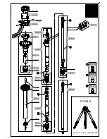
Mountaineer Mk2 Series 1 G1128G G1128G G1128G
Brand: Gitzo Pages: 1

G-SHOT DV511
Brand: Genius Pages: 74

DZ-HV574E
Brand: Hitachi Pages: 46

DZ-HS301E
Brand: Hitachi Pages: 4

DZ-HS303E
Brand: Hitachi Pages: 2

DZ-HV564E
Brand: Hitachi Pages: 54

DZ-MV380A - Camcorder
Brand: Hitachi Pages: 78

DZ-HV575E
Brand: Hitachi Pages: 48

DZ-HV1079E
Brand: Hitachi Pages: 53

DZ-MV200A - Camcorder
Brand: Hitachi Pages: 104

DZ-HV1074
Brand: Hitachi Pages: 100

DZ-MV1000E
Brand: Hitachi Pages: 174

DZ-HS503
Brand: Hitachi Pages: 163

DZ-HS803A - Camcorder
Brand: Hitachi Pages: 191

DZ-MV550A - Camcorder
Brand: Hitachi Pages: 187

DZ-MV270A - Camcorder
Brand: Hitachi Pages: 114

DZ-HS500E
Brand: Hitachi Pages: 164

DZ-MV4000E
Brand: Hitachi Pages: 128


