VQT2U23
ENGLISH
SS0810RI0 -PS
D
Printed in Japan
Operating Instructions
Vol.1
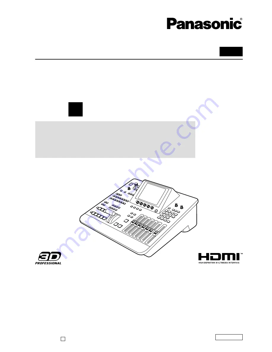
Digital AV Mixer
Model No.
AG-HMX100P
Model No.
AG-HMX100E
Volume
1
Note that Operating Instructions Vol. 1 describes basic
operations of the digital AV mixer.
For instructions on advanced operations of the digital
AV mixer, refer to Operating Instructions Vol. 2 (pdf file)
contained in the supplied CD-ROM.
Before operating this product, please read the instructions carefully and save this manual for future use.