background image

Il presente manuale è parte integrante del prodotto.
Si raccomanda di leggere attentamente le istruzioni prima 
dell’installazione, manutenzione o utilizzo del prodotto.

This manual is an integral part of the product.
Read the instructions carefully before installing, servicing or 
operating the product.

Die vorliegende Anleitung ist fester Bestandteil des Produkts.
Vor der Installation, Wartung und Verwendung die Anleitungen 
stets aufmerksam durchlesen.

Le présent manuel fait partie intégrante du produit.
Il est conseillé de lire attentivement les consignes 
avant l'installation, l'entretien ou l'utilisation du produit.

Este manual es parte integrante del producto.
Se recomienda leer detenidamente las instrucciones antes 
de la instalación, el mantenimiento y el uso del producto..
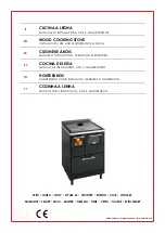
ECOFIRE

®

VIOLETTA

STUFE A PELLET 

-

  PELLET STOVES

PELLETOFEN - POÊLES À GRANULÉS - PELLET ESTUFA

Summary of Contents for Ecofiore Violetta

Page 1: ...ester Bestandteil des Produkts Vor der Installation Wartung und Verwendung dieAnleitungen stets aufmerksam durchlesen Le présent manuel fait partie intégrante du produit Il est conseillé de lire attentivement les consignes avant l installation l entretien ou l utilisation du produit Este manual es parte integrante del producto Se recomienda leer detenidamente las instrucciones antes de la instalac...

Page 2: ... nous avez accordée en achetant notre produit et vous félicitions pour votre choix Q GH YRXV SHUPHWWUH GH SUR WHU DX PLHX GH YRWUH QRXYHDX SRrOH QRXV YRXV LQYLWRQV j suivre attentivement les instructions reportées dans cette notice Estimado Cliente Deseamos agradecerle por la preferencia que nos ha otorgado adquiriendo nuestro producto y lo felicitamos por su elección Para el mejor uso de su nueva...

Page 3: ...3 888 247 1050 509 117 968 354 O 80 118 180 O 8 0 O 8 0 287 DIMENSIONI DIMENSIONS DIMENSIONS ABMESSUNGEN DIMENSIONES VIOLETTA Dimensioni mm Dimensions mm Abmessungen mm Dimensions mm Dimensiones mm ...

Page 4: ...UM SWITCH PRESSOSTAT DRUCKWAECHTER PRESOSTATO 6 TERMOSTATO DI SICUREZZA THERMOSTAT THERMOSTAT RAUMTEMPERATURREGLER TERMOSTATO 7 SONDA AMBIENTE ROOM PROBE SONDE AMBIANT RAUMSONDE SONDA AMBIENTE 8 SONDA PELLET PELLET PROBE SONDE PELLET PELLETSONDE SONDA PELLET 9 SONDA FUMI FLUE PROBE SONDE DES FUMEES RAUCHSONDE SONDA HUMOS 10 PANNELLO COMANDI DISPLAY TABLEAU DE COMMANDE STEUERPANEEL PANEL DE MANDO 1...

Page 5: ... 95 91 91 Temperatura fumi Smoke temperature Tempèrature fumèes Rauchtemperature Temperatura humos 78 C 145 C Portata fumi 6PRNH ÀRZ UDWH pELW GH IXPpH 5DXFKPHQJH 9ROXPHQ GH KXPRV 2 6 g s 5 1 g s Consumo orario di combustibile Hourly consumptiono Consommation horaire 0 6 kg h 1 63 kg h Emissioni di CO al 13 di O2 CO emission at 13 of O2 CO Abgabe 13 des O2 697 mg Nm3 117 mg Nm3 ePLVVLRQV GH 2 j G ...

Page 6: ... CO 13 O 2 potenza ridotta 13 O 2 heat output 13 O 2 Teillast 13 O 2 réf 13 O 2 j UHI 2 2 a puissance partielle potencia parcial d Distanza minima da Distance between sides Mindestabstand zu Distance minimum avec Distancia mínima con PDWHULDOL LQ DPPDELOL DQG FRPEXVWLEOH PDWHULDOV EUHQQEDUHQ DXWHLOHQ PLQG PDWpULDX LQÀDPPDEOHV PDWHULDOHV LQÀDPPDEOHV V Tensione Voltage Spannung Tension Tensión f Fre...

Page 7: ...OMBURENTE 6 5 SCARICO FUMI 6 6 LIVELLAMENTO DELLA STUFA 6 7 ALLACCIAMENTO AGLI IMPIANTI 6 8 COLLEGAMENTO AD UN IMPIANTO DI DISTRIBUZIONE DELL ARIA 7 FUNZIONAMENTO 7 1 PANNELLO COMANDI 7 2 PARAMETRI DI FUNZIONAMENTO 7 3 ACCESSO AI MENU 8 OPERAZIONI PRELIMINARI 8 1 CARICAMENTO PELLET 8 2 ALIMENTAZIONE ELETTRICA 8 3 IMPOSTAZIONI INIZIALI 9 UTILIZZO DELLA STUFA 9 1 ACCENSIONE 9 2 MODIFICA DEI PARAMETR...

Page 8: ...tto oggetto del presente manuale è costruito e collaudato seguendo le prescrizioni di sicurezza indicate nelle direttive europee di riferimento Questo manuale è indirizzato ai proprietari della stufa agli installatori utilizzatori e manutentori delle stufe ed è parte integrante del prodotto In caso di dubbi sul contenuto e per ogni chiarimento contattare il costruttore o il servizio di assistenza ...

Page 9: ...OD LRQH QRQ FRQIRUPH DOOH QRUPDWLYH vigenti nel paese ed alle direttive di sicurezza LQRVVHUYDQ D SDU LDOH R WRWDOH GHOOH LVWUX LRQL contenute nel manuale LQVWDOOD LRQH GD SDUWH GL SHUVRQDOH QRQ TXDOL FDWR H QRQ DGGHVWUDWR XVR QRQ FRQIRUPH DOOH GLUHWWLYH GL VLFXUH D PRGL FKH H ULSDUD LRQL QRQ DXWRUL DWH GDO Costruttore effettuate sulla stufa XWLOL R GL ULFDPEL QRQ RULJLQDOL R QRQ VSHFL FL per il m...

Page 10: ...funzionante 7RJOLHUH O DOLPHQWD LRQH HOHWWULFD SULPD GL intervenire su parti elettriche elettroniche e connettori 2 3 AVVERTENZE PER L UTILIZZATORE Predisporre il luogo d installazione della stufa secondoiregolamentilocali nazionaleedeuropei D VWXID HVVHQGR XQ SURGRWWR GD ULVFDOGDPHQWR SUHVHQWD GHOOH VXSHU FL HVWHUQH SDUWLFRODUPHQWH calde Per questo motivo si raccomanda la massima cautela durante ...

Page 11: ... di utilizzo della stufa o in un locale attiguo purché sia a temperatura e umidità accettabili Il pellet umido e o freddo 5 C riduce la potenzialità termica del combustibile ed obbliga ad effettuare maggiore manutenzione di pulizia del braciere materiale incombusto e del focolare Porre particolare attenzione nello stoccaggio e movimentazione dei sacchi di pellet Deve essere evitata la sua frantuma...

Page 12: ...ntemporaneamente l aspirazione di aria comburente al braciere Lavora in parallelo al sistema di caricamento e varia la potenzialità di scarico dei fumi in funzione della potenza termica H Sistema di caricamento È composto da un motoriduttore e da un dosatore e permette la discesa del pellet nel braciere I Scheda elettronica L Interruttore di accensione M Termostato a riarmo manuale posto sul monta...

Page 13: ...QIRUWXQLVWLFL individuali e personali siano integri e perfettamente funzionanti C deve indossare i guanti antinfortunistici D deve indossare scarpe antinfortunistiche E deve usufruire di utensili muniti di isolamento elettrico F deve accertarsi che l area interessata alle fasi di montaggio e di smontaggio sia libera da ostacoli 6 3 LUOGO DI INSTALLAZIONE DELLA STUFA Q JXUD LJ VRQR LQGLFDWH OH GLVW...

Page 14: ...zionata in modo da non essere ostruita accidentalmente Nel caso fosse impossibile realizzare la presa d aria esterna nella parete posteriore alla stufa parete non perimetrale deve essere realizzato un foro in una parete esterna del locale dove viene posizionata la stufa Se non fosse possibile realizzare la presa d aria esterna nel locale è possibile realizzare il foro esterno in un locale adiacent...

Page 15: ...are un massimo di 3 variazioni di direzione oltre a quello derivante dal collegamento posteriore della stufa al camino utilizzando delle curve a 45 90 o dei raccordi a 7HH J Utilizzare sempre un raccordo a Tee con tappo di ispezione ad ogni variazione orizzontale e verticale del percorso di scarico fumi Se possibile sul primo Tee all uscita dello scarico fumi della stufa collegare un tubo per l ev...

Page 16: ...o dei fumi attraverso un camino tradizionale Fig 5 8 può essere fatto purché ci si assicuri sullo stato di manutenzione del camino In caso di camino di sezione maggiore è necessario intubare il camino con una tubazione in acciaio con diametro in funzione del percorso opportunamente isolato Fig 5 9 Assicurarsi che il collegamento al camino in muratura sia opportunamente sigillato In caso di passagg...

Page 17: ... HOHWWULFR attraverso la spina in dotazione Il collegamento elettrico spina deve essere facilmente accessibile anche dopo l installazione della stufa Se il cavo di alimentazione risulta danneggiato deve essere sostituito dal servizio di assistenza tecnica o GD XQ WHFQLFR TXDOL FDWR LQ PRGR GD SUHYHQLUH RJQL rischio MESSA A TERRA È obbligatorio che l impianto sia provvisto di messa a terra e di int...

Page 18: ...cui è installata la stufa stessa STUFE CANALIZZABILI Attraverso l attrezzo in dotazione o alla leva di deviazione dell aria in base al modello è possibile DJLUH VXO FRPDQGR SHU GHYLDUH LO ÀXVVR GHOO DULD calda dall ambiente dove è installata la stufa al condotto di canalizzazione e viceversa Fig 6 5 Per collegare la stufa all impianto di canalizzazione ULPXRYHUH LO WDSSR VYLWDQGR OH GXH YLWL GL VV...

Page 19: ...o premuto uno dei due tasti freccia si attiva lo scorrimento veloce 7 2 PARAMETRI DI FUNZIONAMENTO Durante il funzionamento la stufa si regola automaticamente in funzione dei valori impostati che vengono visualizzati sul display POTENZA P Rappresenta la potenza di riscaldamento a cui lavora la stufa E possibile impostare un valore compreso tra A automatico 1 minimo 2 3 4 5 massimo Impostando il va...

Page 20: ... menu attivabile Comando sugli angoli in prossimità di uno dei quattro tasti potrebbe esserci un simbolo e oppure le diciture in corsivo ok x questi comandi sono attivabili con la pressione del tasto immediatamente vicino Legenda comandi ok attraverso la pressione del tasto conferma OH PRGL FD HIIHWWXDWD x attraverso la pressione del tasto OFF esce da quella visualizzazione e ritorna alla preceden...

Page 21: ...Prima di utilizzare la stufa è necessario impostare la lingua la data e l ora corrente 8 3 1 Impostazione lingua Portarsi nel MENU SET STUFA seguendo la Procedura per accedere ai menù descritta nel paragrafo e premere OK 1 Scorrere con i tasti o i sottomenu 2 Selezionare con il tasto il menu LINGUA 3 Scegliere la lingua desiderata con i tasti o 4 Confermare la scelta con il tasto ok 5 Premere il t...

Page 22: ...R per DFFHGHUH DO PHQX GL PRGL FD GHL SDUDPHWUL LJ Sul display appariranno i parametri P V T e 4 indicazioni sulle funzioni dei tasti del menu OK X Per spostarsi da un parametro all altro premere il tasto OK Il parametro selezionato ODPSHJJHUj H SHU PRGL FDUQH LO YDORUH SUHPHUH LO tasto oppure Una volta impostati tutti i parametri premere il tasto OFF X per uscire dal menu 3HU PRGL FDUH L SDUDPHWU...

Page 23: ...a dicitura Programma nel terzo caso tale dicitura verrà alternata con la dicitura Set t amb set temperatura ambiente Il secondo parametro quello al centro consente di decidere a che ora la stufa si deve accendere Selezionare l ora desiderata e premere oppure impostare il valore OFF scorrendo l orario si trova tra le 23 50 e le 00 00 per disabilitare la funzione di accensione Il display visualizzer...

Page 24: ...RQGD ULJD H LQL LHUDQQR D ODPSHJJLDUH L YDUL JLRUQL GHOOD VHWWLPDQD DJHQGR VXO WDVWR FL VSRVWLDPR QR D IDU ODPSHJJLDUH 9 9HQHUGu H OR DELOLWLDPR FRQ LO WDVWR 5LSHWLDPR O RSHUD LRQH SHU DELOLWDUH DQFKH 6 6DEDWR H RPHQLFD O ULVXOWDWR VDUj TXHOOR LOOXVWUDWR LQ LJ H FLRq q VWDWR DWWLYDWR LO SURJUDPPD 3 DYHQGR LQVHULWR OD VWXID FHUFKHUj GL SRUWDUH O DPELHQWH D FRQ SRWHQ D H YHQWLOD LRQH DXWRPDWLFKH Q T...

Page 25: ...nderà automaticamente al ritorno dell alimentazione se ci sono le condizioni opportune Se tali condizioni non sono soddisfatte il display visualizzerà Allarme Black Out e la stufa dovrà essere ripristinata manualmente secondo quanto riportato nel capitolo12 10 6 LETTURA ORE DI FUNZIONAMENTO SRVVLELOH YHUL FDUH OH RUH WRWDOL GL IXQ LRQDPHQWR GHOOD VWXID R OH RUH UHVLGXH FKH UHVWDQR SULPD GL HIIHWWX...

Page 26: ...pegnere la stufa al raggiungimento della temperatura ambiente impostata SET T AMB e riavviarla al raggiungimento della temperatura ambiente minima impostata TEMP START E possibile impostare due parametri Il primo ON OFF abilita o disabilita tale funzione O VHFRQGR GH QLVFH OD WHPSHUDWXUD DOOD TXDOH OD VWXID VL riaccenderà Quando questa funzione è attiva sul display compare il simbolo La scritta ST...

Page 27: ...uello selezionato lampeggerà 0RGL FDUQH LO YDORUH FRQ L WDVWL o RQIHUPDUH OD PRGL FD FRQ LO WDVWR ok 9 Premere il tasto OFF x per uscire dal sottomenu ripremerlo eventualmente per uscire dai menu superiori Le funzioni STAND BY e SET T NOTTE sono funzioni di auto ON OFF Cioè la loro attivazione può accendere o spegnere la stufa senza l intervento dell utente ...

Page 28: ...lori di sicurezza impostati Mancanza di corrente quando la stufa è in funzione Necessità di manutenzione straordinaria Difettosità di qualche componente Procedura standard Ripristino allarmi VENTILATORE FUMI 6L DWWLYD TXDQGR VL YHUL FD XQD DQRPDOLD al funzionamento del ventilatore di estrazione dei fumi Difettosità del ventilatore di estrazione dei fumi Procedura standard Ripristino allarmi SONDA ...

Page 29: ...a stufa Fig 13 A attraverso le griglie frontali o superiori in base al modello L altra è quella che permette di riscaldare anche ambienti distanti dalla stufa Fig 13 B predisponendo un impianto di canalizzazione dell aria 3HU GHYLDUH LO ÀXVVR GHOO DULD FDOGD FRPSOHWDPHQWH o parzialmente da una parte o dall altra utilizzare l apposito utensile in dotazione con la stufa e agire sul comando posto tra...

Page 30: ... STUFA Questa funzione consente di pulire la stufa evitando la dispersione della cenere Durante l operazione il ventilatore fumi è alla massima velocità impedendo così alle ceneri di uscire dal focolare Si attiva solo a stufa completamente fredda Premere il tasto OFF per 2 secondi Il ventilatore fumi si attiverà alla massima potenza Al termine si spegnerà da solo Per interrompere l operazione prem...

Page 31: ...le deposito di cenere e fuliggine prima che le stesse otturino il passaggio dei fumi In caso di mancata o inadeguata pulizia la stufa può avere problemi di funzionalità quali cattiva combustione annerimento del vetro intasamento del braciere con accumulo di ceneri e pellet deposito di ceneri ed eccessive incrostazioni sullo scambiatore con conseguente scarso rendimento 14 3 6 Regolazione della Man...

Page 32: ...messo un segnale acustico prolungato e il messaggio MANUTENZIONE STRAORDINARIA verrà YLVXDOL DWR DG LQWHUPLWWHQ D 4XHVWR QR D TXDQGR sarà eseguita la manutenzione straordinaria Si consiglia di concordare con il centro di Assistenza Tecnica Autorizzato un contratto annuale di manutenzione del prodotto Per facilitare le operazioni di manutenzione è possibile accedere alla parte tecnica e fumistica d...

Page 33: ...pera per lo smaltimento dei materiali ed eventualmente per la denuncia di smaltimento ATTENZIONE Tutte le operazioni di smontaggio per la demolizione devono avvenire a stufa ferma e privata dell energia elettrica di alimentazione asportare tutto l apparato elettrico separare gli accumulatori presenti nelle schede elettroniche rottamare la struttura della stufa tramite le ditte autorizzate ATTENZIO...

Page 34: ......

Page 35: ...STOVE 6 7 CONNECTION TO SYSTEMS 6 8 CONNECTION TO AN AIR DISTRIBUTION SYSTEM 7 STOVE DESCRIPTION 7 1 CONTROL PANEL 7 2 OPERATING PARAMETERS 7 3 ACCESSING THE MENUS 8 PRELIMINARY OPERATIONS 8 1 LOADING THE PELLETS 8 2 POWER SUPPLY 8 3 INITIAL SETTINGS 9 STOVE OPERATION 9 1 STARTING THE STOVE 9 2 MODIFYING THE PARAMETERS 9 3 SWITCHING OFF 10 FUNCTIONS AVAILABLE 10 1 TIMER FUNCTION 10 2 STANDBY FUNCT...

Page 36: ...TION The appliance is manufactured and tested to conform with the safety standards indicated in the applicable European directives This manual is intended for owners installers users and maintenance personnel of stoves and is an integral part of the product If there are any doubts regarding the contents of this manual or for any other explanations please contact the manufacturer or an authorised s...

Page 37: ...ivil and criminal direct or indirect deriving from installation not in compliance with the standards in force in the country concerned and with safety directives partial or total failure to follow the instructions provided in this manual LQVWDOODWLRQ E XQTXDOL HG DQG XQWUDLQHG personnel use not in compliance with safety directives PRGL FDWLRQV DQG UHSDLUV RQ WKH VWRYH WKDW DUH not authorised by th...

Page 38: ...power before working on electrical or electronic parts and connectors 2 3 WARNINGS FOR THE USER Prepare the stove installation site in accordance with local national and European regulations As the stove is a heating appliance it has very hot outside surfaces For this reason maximum FDUH PXVW EH SDLG GXULQJ RSHUDWLRQ VSHFL FDOO do not touch or get too close to the glass door to avoid getting burne...

Page 39: ...llets in the same room where the stove is installed or an adjacent room as long as the temperature and humidity are acceptable Damp and or cold pellets 5 C reduce the fuel heat value and mean the burn pot unburned PDWHULDO DQG UHER ZLOO QHHG WR EH FOHDQHG PRUH frequently Pay special care when storing and handling the sacks of pellets Make sure these are not crushed to prevent the pellets from beco...

Page 40: ...smoke and the simultaneous intake of air for combustion to the hearth It works in parallel with the loading system and varies the volume discharged according to the heat output H Loading system It consists of a gear motor and screw for dosing the hearth with pellets I Electronic card L Stove ignition switch M Manually resettable thermostat placed on the side of the stove I L M H G A E B C F D M ...

Page 41: ... EH LQ D W PHQWDO SK VLFDO VWDWH for working and make sure that personal protective equipment is in perfectly working order C always wear safety gloves D always wear safety shoes E always use electrically insulated tools F make sure that the area being used for assembly and dismantling is clear of any obstacles 6 3 STOVE INSTALLATION SITE Figure 5 2 shows the minimum clearance there should be DURX...

Page 42: ...ts Make sure that the air vent is located in such a way that it can t be accidentally obstructed If it s not possible to make a fresh air opening in the wall behind the stove not a perimeter wall an opening must be made on the wall in the room where the stove is installed that faces the outside If no fresh air opening can be made in the room it can be made in an adjacent room as long as the two ro...

Page 43: ...e at least three changes in direction DORQJ WKH ÀXH LQ DGGLWLRQ WR WKH ÀXH FRQQHFWLRQ at the rear of the stove using 45 or 90 angle connectors or T connectors Fig 5 7 Use always a T connector with inspection cap on DOO KRUL RQWDO RU YHUWLFDO FKDQJHV LQ ÀXH GLUHFWLRQ If it is possible connect a pipe at the bottom of the T junction in order to discharge the smoke condensate WKDW FRXOG IRUP LQ WKH ÀX...

Page 44: ...w and affect proper stove operation 7KH ÀXH JDV FDQ EH GLVFKDUJHG WKURXJK D WUDGLWLRQDO chimney Fig 5 8 as long as you make sure on the state of maintenance of the chimney For larger chimneys suitably insulated steel pipes need to be inserted on the inside diameter according to the length Fig 5 9 Makes sure connections to brick chimneys are suitably sealed I WKH ÀXHV UXQ WKURXJK ZRRGHQ URRIV RU ZD...

Page 45: ...ical connection Simply connect the stove to the electricity mains with the plug supplied The electrical connection plug must be easy to access also after the stove has been installed If the power lead is damaged it must be replaced E WKH WHFKQLFDO DVVLVWDQFH VHUYLFH RU D TXDOL HG electrician to prevent all risks 6 7 2 Earthing 7KH V VWHP PXVW EH HDUWKHG DQG WWHG ZLWK D FLUFXLW breaker as provided ...

Page 46: ...m where the stove is installed DUCTED STOVES 8VLQJ WKH WRRO VXSSOLHG RU WKH DLU GHÀHFWRU OHYHU EDVHG RQ WKH PRGHO WKH ÀRZ RI KRW DLU FDQ EH GHYLDWHG IURP the room where the stove is installed to the ducting and vice versa Fig 6 5 To connect the stove to the ducting system remove the cap by unscrewing the two fastening screws that secure the duct closure cap on the rear of the stove STOVES READY TO...

Page 47: ...matically adapts its operation based on the set values as shown on the display POWER P This represents the stove s heat output or power level The possible values are A automatic 1 minimum 2 3 4 5 maximum If setting the value A the stove will attempt to heat the room to the set temperature managing the power level completely automatically FAN V This represents the hot air fan speed The possible val...

Page 48: ...in the corners near any of the four buttons the action in question is activated by pressing the corresponding button Actions ok pressing the EXWWRQ FRQ UPV WKH FKDQJHV made x pressing the OFF button exits the current display and returns to the previous screen pressing the button scrolls the various screens of the display or increases the value of the parameter pressing the button scrolls the vario...

Page 49: ...the stove 8 3 1 language setting Go to the STOVE SETTINGS MENU following the Procedure for accessing the menus and press OK 1 Scroll the submenus using the or button 2 Use the button to select the LANGUAGE menu 3 Select the desired language using the or button RQ UP WKH VHOHFWLRQ E SUHVVLQJ ok 5 Press OFF x to exit the submenu press the same button again if necessary to go back another menu level ...

Page 50: ... of the display to modify the parameters simply press the button to access the menu for modifying the parameters Fig 9 1 The display will show the parameters P F T and four symbols indicating the functions of the menu buttons OK X To move from one parameter to the next press 2 7KH VHOHFWHG SDUDPHWHU ZLOO ÀDVK WKHQ WR modify the value press or Once all the parameters have been set press OFF X to ex...

Page 51: ...e third case this message will alternate with the message Set room t set room temperature The second parameter LQ WKH FHQWUH GH QHV ZKDW time the stove will start Select the desired time and press or alternatively select OFF scrolling the times this comes between 23 50 and 00 00 to disable the start time The display will show Start Timer The third parameter RQ WKH ULJKW GH QHV ZKDW time the stove ...

Page 52: ...cond row and the YDULRXV GD V RI WKH ZHHN ZLOO VWDUW ÀDVKLQJ use the EXWWRQ XQWLO ULGD LV ÀDVKLQJ and then select this by pressing Repeat the same step to select S Saturday and Su Sunday The result will be as illustrated in Fig 10 3 i e program P2 has been enabled having entered 25 the stove will try to heat the room to 25 C with automatic heat output and fan operation In this case the stove will ...

Page 53: ...will restart automatically when power returns if the conditions DUH ULJKW I VXFK FRQGLWLRQV DUH QRW IXO OOHG WKH GLVSOD ZLOO VKRZ ODFN 2XW ODUP DQG WKH VWRYH PXVW EH UHVHW manually as described 10 6 READING THE OPERATING HOURS The display can show total stove operating hours or the number of hours remaining before recommended maintenance is required to be performed by the Service Centre Pressing a...

Page 54: ...ady operating conditions the stove can be switched off when reaching the set room temperature SET ROOM T and start again when reaching the set minimum room temperature START TEMP Two parameters can be set 7KH UVW 21 2 HQDEOHV RU GLVDEOHV WKH IXQFWLRQ 7KH VHFRQG GH QHV WKH WHPSHUDWXUH IRU UHVWDUWLQJ WKH VWRYH When this function is active the display shows the symbol STAND BY is displayed when the r...

Page 55: ... SDUDPHWHU ZLOO EH ÀDVKLQJ 7 Modify the value using the or button RQ UP WKH VHWWLQJ E SUHVVLQJ ok 9 Press OFF x to exit the submenu press the same button again if necessary to go back another menu level The STAND BY and NIGHT SET T functions are auto ON OFF functions In other words when enabled they can start or switch the stove off without input from the user ...

Page 56: ...erature in the pellet hopper exceeds the set safety values Power failure when the stove is operating Special maintenance required Faulty component Standard procedure Reset alarms FLUE FAN This alarm is activated when a fault occurs LQ WKH RSHUDWLRQ RI WKH ÀXH JDV H KDXVW IDQ Flue gas exhaust fan fault Standard procedure Reset alarms PELLET FLUE PROBE This alarm is activated when a fault occurs in ...

Page 57: ... Fig 13 A through the front or top grills according to the model The other is used to heat other rooms away from the stove Fig 13 B through a system of air ducts 7R GHYLDWH WKH ÀRZ RI KRW DLU FRPSOHWHO RU SDUWLDOO from one outlet to the other use the special tool supplied with the stove and adjust the control placed between the front grills 6RPH PRGHOV RI VWRYH DUH DOUHDG WWHG ZLWK D OHYHU to devi...

Page 58: ...maintenance tools 2QFH WKH PDLQWHQDQFH RU UHSDLU ZRUN LV QLVKHG reinstall all the protections and reactivate all the safety devices before turning the stove back on 14 2 ROUTINE MAINTENANCE FOR THE USER 14 2 1 OHDQLQJ WKH LQVLGH RI WKH UHER The stove requires a simple but frequent and thorough clean to guarantee it will work properly and to ensure FRQVWDQW KHDW HI FLHQF Clean only when the stove i...

Page 59: ...ere are any horizontal sections you must check and remove any ash or soot that may have deposited before they have the chance to close the smoke passage Failure to clean or clean thoroughly will probably lead to stove operating problems such as bad combustion blackening of the glass clogging of the hearth with an accumulation of ash and pellets deposit of ash and encrustation on the exchanger OHDG...

Page 60: ...recommend drawing up an annual maintenance contract for the product with the Authorised Technical Assistance Centre Q RUGHU WR DFFHVV WR WKH WHFKQLFDO DQG ÀXH SDUW RX just need to spin the two lateral panels as shown in the picture Fig 14 5 INSPECTION AND MAINTENANCE PLAN WHENEVER STARTED WEEKLY 1 MONTH 1 YEAR a Burn pot X Ash bin Compartment X Glass X Heat exchanger X Ignition heater socket X Flu...

Page 61: ...stallation as regards the disposal of materials and if necessary the report of disposal ATTENTION all dismantling operations for demolition must be carried out when the stove is not working and not electrically powered remove all the electrical parts separate the storage batteries from the electronic cards scrap the stove s structure by way of authorised companies ATTENTION dumping the stove in ac...

Page 62: ......

Page 63: ...HRUNG 6 6 NIVELLIEREN DES HEIZOFENS 6 7 VERSCHIEDENE ANSCHLÜSSE 6 8 ANSCHLUSS AN EIN LUFTLEITSYSTEM 7 BESCHREIBUNG DES OFENS 7 1 BEDIENPANEL 7 2 BETRIEBSPARAMETER 7 3 ÖFFNEN DER MENÜS 8 VORBEREITUNG 8 1 PELLETZUFÜHRUNG 8 2 STROMVERSORGUNG 8 3 ANFÄNGLICHE EINSTELLUNGEN 9 GEBRAUCH DES OFENS 9 1 EINSCHALTEN 9 2 BEARBEITEN DER PARAMETER 9 3 ABSCHALTEN 10 VERFÜGBARE FUNKTIONEN 10 1 TIMER FUNKTION 10 2 ...

Page 64: ...eserAnleitungbetroffeneProduktwirdgemäß den Sicherheitsvorschriften der EU Bezugsrichtlinien gebaut und geprüft Dieses Handbuch ist wesentlicher Bestandteil des Produkts und für die Eigentümer des Ofens sowie für die Installationstechniker Betreiber und WartungstechnikervonÖfenbestimmt ImZweifelsfall und für eventuelle Rückfragen wenden Sie sich bitte an den Hersteller oder an den Vertragskundendi...

Page 65: ...ation in Abweichung von den im Installationsland geltenden Bestimmungen und von den Sicherheitsvorschriften Teilweise oder gänzliche Missachtung der in diesem Handbuch enthaltenen Anleitungen QVWDOODWLRQ GXUFK QLFKW TXDOL LHUWHV XQG QLFKW geschultes Personal von den Sicherheitsrichtlinien abweichender Gebrauch nicht vom Hersteller genehmigte am Ofen vorgenommene Umbauten und Reparaturen Verwendung...

Page 66: ...cht funktionstüchtig Vor Eingriffen an elektrischen elektronischen Teilen oder Steckverbindern die Spannungszufuhr unterbrechen 2 3 HINWEISE FÜR DEN BENUTZER HUHLWHQ 6LH GHQ XIVWHOOXQJVRUW GHV 2IHQV JHPl den lokalen nationalen und europäischen Bestim mungen vor Da der Ofen als Heizgerät dient werden seine Au HQÀlFKHQ EHVRQGHUV KHL HVKDOE LVW ZlKUHQG des Betriebs maximale Vorsicht geboten insbe son...

Page 67: ...rt werden V HPS HKOW VLFK HLQ SDDU 6lFNH 3HOOHWV LP Aufstellungsraum des Ofens oder in einem benachbarten Raum zu lagern damit sie eine akzeptable Temperatur und Feuchtigkeit haben Feuchte und oder kalte 5 C Pellets reduzieren die Wärmeleistung des Brennstoffs und zwingen zu einer KlX JHUHQ 5HLQLJXQJVZDUWXQJ GHU UHQQVFKDOH unverbranntes Material und des Feuerraums Bei Lagerung und Handhabung der P...

Page 68: ...ung von Verbrennungsluft ins Feuerbecken Arbeitet parallel zur Beschickungsschnecke und regelt den Rauchabzug je nach Wärmeleistung H Beschickungssystem Bestehend aus einem Getriebemotor und einer Schnecke ermöglich das Dosieren der Pellets im Feuerbecken I Elektronik Platine L Schalter zum Einschalten des Heizofens M Sicherheitstemperaturbegrenzer mit manueller Rückstellung im Seitenteil des Ofen...

Page 69: ...ch vergewissern dass die persönlichen Schutzausrüstungen vollständig und funktionstüchtig sind C muss er Schutzhandschuhe tragen D muss er Sicherheitsschuhe tragen E muss er elektrisch isoliertes Werkzeug benutzen F muss er sicherstellen dass der Bereich in dem die Montage und Demontagearbeiten ausgeführt werden frei von Hindernissen ist 6 3 AUFSTELLUNGSORT DES OFENS In der Abbildung Abb 5 2 sind ...

Page 70: ...h verstopfen kann Falls an der Wand hinter dem Ofen kein Außenlufteinlass angebracht werden kann keine Außenwand muss die Öffnung an einer anderen Außenwand des Aufstellungsraumes angebracht werden Sollte es nicht möglich sein im Raum einen Außenlufteinlass anzubringen kann er in einem benachbarten über ein Lüftungsgitter ständig mit dem Aufstellungsraum verbundenen Raum ausgeführtwerden Abb 5 4 C...

Page 71: ...te die Richtung nicht mehr als 3 Mal gewechselt werden dazu 45 90 Rohrkrümmer oder T Stücke verwenden Abb 5 7 Bei jeder waagerechten und senkrechten Richtungsänderung der Abgasführung immer ein T Stück mit Inspektionsklappe verwenden Wenn es möglich ist ein Rohr unten im ersten T Stück der Abgasführung verbinden um den Rauchabzug des Kondenswassers das sich in dem Schornstein bilden kann zu ermögl...

Page 72: ...eb des Ofens Es ist möglich den Rauchabzug in einem traditionellen Kamin Abb 5 8 einzubauen sofern dieser in gutem Zustand ist Wenn der Schornstein einen größeren Querschnitt hat muss er mit einem angemessen isolierten Stahlrohr verrohrt werden Durchmesser je nach Leitungsverlauf Abb 5 9 Sicherstellen dass der Anschluss am gemauerten Schornstein gut abgedichtet ist Wenn Rohre durch Holzdächer oder...

Page 73: ...chluss Den Heizofen einfach mit dem Stecker an die häusliche Stromleitung anschließen Der Elektroanschluss Stecker muss auch nach der Installation des Heizofens mühelos zugänglich sein Sollte das Netzkabel beschädigt sein muss es vom Personal des Technischen Kundendiensts oder von einem Fachmann ersetzt werden um jedes Risiko zu vermeiden 6 7 2 Erdung Die Anlage muss obligatorisch mit einer Erdung...

Page 74: ...n denAufstellungsraum des Ofens geleitet wird KANALISIERBARE ÖFEN Mit dem mitgelieferten Werkzeug oder mit dem Luftumlenkhebel je nach Modell kann die Steuerung zur Umlenkung des warmen Luftstroms aus dem Aufstellungsraum zum Kanalisierungsrohr und umgekehrt betätigt werden Abb 6 5 Für denAnschluss des Ofens an die Kanalisierungsanlage die zwei Befestigungsschrauben mit denen die Abdeckung der Kan...

Page 75: ...BETRIEBSPARAMETER Während des Betriebs wird der Ofen automatisch anhand der eingestellten auf dem Display angezeigten Werte geregelt LEISTUNG P Die Heizleistung bei der der Ofen arbeitet Es kann ein Wert zwischen A Automatisch 1 kleinste Leistungsstufe 2 3 4 5 höchste Leistungsstufe eingestellt werden Bei Einstellung von A wird der Ofen versuchen den Raum auf die gewünschte Temperatur zu bringen u...

Page 76: ... Tasten könnte sich ein Symbol und oder die Q HLJHQ RN EH QGHQ GLHVH HIHKOH N QQHQ GXUFK U FNHQ GHU GDQHEHQ EH QGOLFKHQ 7DVWH aktiviert werden Zeichenerklärung Befehle ok Durch Drücken der Taste wird die vorgenommene Änderung bestätigt x Durch das Drücken der Taste OFF wird die Anzeige geschlossen um zur vorhergehenden Anzeige zurückzugehen Durch Drücken der Taste werden die verschiedenen Anzeigen...

Page 77: ...zeit eingestellt werden 8 3 1 Sprache einstellen Das MENÜ OFENSOLLWERTE mit der in Abschnitt Prozedur Öffnen der Menüs öffnen und OK drücken 1 Mit den Tasten bzw durch die Untermenüs blättern 2 Mit der Taste das Menü SPRACHE wählen 3 Mit den Tasten bzw die gewünschte Sprache wählen 4 Die Wahl mit der Taste ok bestätigen 5 Die Taste OFF x drücken um das Untermenü zu schließen gegebenenfalls erneut ...

Page 78: ...bearbeiten zu öffnen und die Parameter zu ändern siehe Abb 9 1 Auf dem Display erscheinen die Parameter P V T und 4 Angaben über die Funktionen der Tasten des Menüs OK X Um von einem Parameter zum anderen zu wechseln die Taste OK drücken Der gewählte Parameter blinkt und sein Wert kann mit der Taste bzw geändert werden Nach Einstellung aller Parameter die Taste OFF X drücken um das Menü zu schließ...

Page 79: ...el mit SW Raumt Sollwert Raumtemperatur Mit dem zweiten Parameter dem mittleren wird gewählt um wie viel Uhr der Ofen eingeschaltet werden soll Die gewünschte Uhrzeit wählen und drücken oder den Wert OFF einstellen dieser ist beim Scrollen GHU 8KU HLWHQ ZLVFKHQ XQG X QGHQ um die Einschaltfunktion zu deaktivieren Auf dem Display erscheint die Anzeige Start Timer Mit dem dritten Parameter rechts wir...

Page 80: ...XI GLH ZHLWH HLOH XQG GLH YHUVFKLHGHQHQ RFKHQWDJH EHJLQQHQ X EOLQNHQ GXUFK HWlWLJHQ GHU 7DVWH GHQ XUVRU EHZHJHQ ELV Ä U UHLWDJ EOLQNW 0LW GHU 7DVWH EHVWlWLJHQ HQ 9RUJDQJ ZLHGHUKROHQ XP DXFK Ä6D 6DPVWDJ XQG Ä6R 6RQQWDJ X DNWLYLHUHQ DV UJHEQLV LVW DXI EE 10 GDUJHVWHOOW G K GDV 3URJUDPP Ä3 ZXUGH DNWLYLHUW GD Ä HLQJHJHEHQ ZXUGH ZLUG GHU 2IHQ YHUVXFKHQ GLH 5DXPWHPSHUDWXU PLW DXWRPDWLVFKHU HLVWXQJV XQG ...

Page 81: ...ei Rückkehr der Stromversorgung automatisch wieder eingeschaltet sofern die Voraussetzungen hierfür erfüllt sind Sollten diese Voraussetzungen nicht erfüllt sein erscheint auf dem Display die Anzeige Alarm Blackout und der Ofen muss gemäß von Hand wieder in Betrieb gesetzt werden 10 6 LESEN DER BETRIEBSSTUNDEN Es ist möglich die Gesamtbetriebsstunden des Ofens bzw die noch bis zur Durchführung der...

Page 82: ... eingestellten Mindestraumtemperatur TEMP START wieder einzuschalten Es können zwei Parameter eingestellt werden Der erste ON OFF aktiviert bzw deaktiviert diese Funktion Der zweite bestimmt die Temperatur bei der der Ofen wieder eingeschaltet wird Wenn diese Funktion aktiv ist erscheint auf dem Display das Symbol Die Anzeige STANDBY e r s c h e i n t s o b a l d d i e Raumtemperatur über der in T...

Page 83: ...lte blinkt 7 Den Wert mit den Tasten oder ändern 8 Die Änderung mit der Taste ok bestätigen 9 Die Taste OFF x drücken um das Untermenü zu schließen gegebenenfalls erneut drücken um die übergeordneten Menüs zu schließen Die Funktionen STANDBY und SW NACHTT sind Funktionen des automatischen ON OFF Das heißt durch ihre Aktivierung kann der Ofen ohne Eingreifen des Benutzers ein oder ausgeschaltet wer...

Page 84: ...e Temperatur des Pelletbehälters die eingestellten Sicherheitswerte übersteigt Stromausfall während des Ofenbetriebs Außerordentliche Wartung erforderlich Ein Bauteil ist defekt Standardprozedur Rücksetzen der Alarme ALARM AKTIV ABGASVENTILATOR Wird bei Betriebsstörung des Abgasventilators aktiviert Abgasventilator defekt Standardprozedur Rücksetzen der Alarme ALARM ABGAS SONDE ALARM AKTIV PELLET ...

Page 85: ...ber die je nach 0RGHOO IURQWVHLWLJ RGHU REHQ EH QGOLFKHQ LWWHU geheizt wird siehe Abb 13 A Die andere ist die Kanalisierung mit der auch entfernte Räume geheizt werden können siehe Abb 13 B Hierzu ist ein Luftleitsystem anzulegen Um den Warmluftstrom ganz oder teilweise von einem Ort zum anderen umzuleiten muss mit dem Werkzeug das dem Ofen beiliegt die Umsteuerung zwischen den frontseitigen Gitte...

Page 86: ... alle Abdeckungen installieren und Schutzvorrichtungen aktivieren bevor der Heizofen wieder in Betrieb genommen wird 14 2 REGELMÄSSIGE INSTANDHALTUNG FÜR DEN BENUTZER 14 2 1 Interne Reinigung der Feuerstelle Der Heizofen benötigt nur eine einfache Instandhaltung GLH DEHU KlX J XQG VRUJIlOWLJ GXUFK XI KUHQ LVW XP HLQH HI LHQWH HLVWXQJ XQG HLQHQ XQJHVW UWHQ HWULHE X gewährleisten Die Reinigung bei k...

Page 87: ...t mindestens zweimal jährlich zu reinigen Anfang und Mitte der Wintersaison Abb 14 4 Bei waagrechten Rauchfangleitungen sind eventuelle Aschen und Russablagerungen zu entfernen bevor sie die Leitung verstopfen Bei fehlender oder unzureichender Reinigung kann der Heizofen folgende Betriebsstörungen aufweisen Schlechte Verbrennung Schwarzwerden der Glasscheibe Verstopfung des Kohlenbeckens durch Asc...

Page 88: ...le Es wird empfohlen mit einer autorisierten Kundendienststelle einen jährlichen Wartungsvertrag abzuschließen Um die Wartungsunternehmen zu erleichtern können die zwei seitliche Verkleidungselemente wie in der Abbildung Abb 14 5 geöffnet werden KONTROLL UND WARTUNGSPROGRAMM BEI JEDER EINSCHAL TUNG JEDE WOCHE 1 MONAT 1 JAHR a Brennschale X Aschekasten fach X Glasscheibe X Kessel X Widerstandhalter...

Page 89: ...1RUPHQ GHV MHZHLOLJHQ DQGV I U GLH QWVRUJXQJ XQG HYHQWXHOOH QWVRUJXQJVPHOGXQJ HLQKDOWHQ ACHTUNG O O H X P E U L V V Q W L J H Q HUOHJXQJVDUEHLWHQ P VVHQ EHL VWLOOVWHKHQGHP HUlW XQG XQWHUEURFKHQHU 6WURP XIXKU YRUJHQRPPHQ ZHUGHQ GLH JDQ H OHNWURDQODJH DEQHKPHQ GLH DWWHULHQ DXV GHQ OHNWURQLNNDUWHQ QHKPHQ GLH HUlWHVWUXNWXU EHU EHIXJWH 8QWHUQHKPHQ YHUVFKURWWHQ ACHTUNG LH 9HUZDKUORVXQJ GHV HUlWV DQ XJlQ...

Page 90: ......

Page 91: ...E DE SA PROPRE AMENÉE D AIR POUR LES APPAREILS ÉTANCHES 9 6 6 ÉVACUATION DE LA FUMÉE 9 6 7 NIVELLEMENT DU POÊLE 11 6 8 BRANCHEMENTS 11 6 9 BRANCHEMENT À UNE INSTALLATION DE DISTRIBUTION DE L AIR 12 7 DESCRIPTION DU POELE 13 7 1 PANNEAU DE COMMANDE 13 7 2 PARAMÈTRES DE FONCTIONNEMENT 13 7 3 ACCES AUX MENUS 14 8 OPERATIONS PRELIMINAIRES 15 8 1 CHARGEMENT DES PELLETS 15 8 2 ALIMENTATION ELECTRIQUE 15...

Page 92: ...WXHU OHV contrôles sur l existence d une entrée d air de combustion et de sa section conformément aux normes en vigueur ainsi que la conformité des 1 PRÉAMBULE Le produit visé par le présent manuel a été construit et assemblé suivant les prescriptions de sécurité indiquées dans les directives européennes de référence Ce manuel est destiné à l usage des utilisateurs des installateurs poseurs et man...

Page 93: ...responsabilité civile et pénale directement ou indirectement dans les cas suivants Installation non conforme aux normes et à la réglementation en vigueur dans l Etat ou le poêle est installé Manque d entretien de la part de l utilisateur ou de l installateur 1RQ UHVSHFW GHV LQVWUXFWLRQV JXUDQW GDQV OH présent manuel Installation faite par des personnes mal ou non formées Utilisation non conforme a...

Page 94: ...LISATEUR 3UpYRLU XQ OLHX G LQVWDOODWLRQ GX SRrOH FRQIRUPH j OD législation locale nationale et européenne S agissant d un appareil de chauffage les surfaces externes du poêle sont particulièrement chaudes La prudence maximale est recommandée pendant son fonctionnement notamment ne pas toucher et ne pas s approcher de la vitre de la porte au risque de se brûler ne pas toucher au raccordement des fu...

Page 95: ... trop froid Nous vous conseillons de conserver quelques sacs de pellets dans le local ou se trouve le poêle RX GDQV XQH SLqFH DGMDFHQWH D Q G DYRLU XQH température et un taux d humidité acceptables HV JUDQXOpV KXPLGHV HW RX IURLGV UpGXLVHQW la puissance thermique du pellet et l on doit procéder à plus de fréquence de nettoyage du brasero imbrûlés Portez une attention particulière à l entreposage e...

Page 96: ...nt l aspiration d air de combustion destiné au brasier RQFWLRQQH HQ SDUDOOqOH DYHF OD YLV VDQV Q GH chargement et régule le débit d évacuation des fumées en fonction de la puissance thermique H Système de chargement Il est constitué d un motoréducteur et d une vis sans Q HW SHUPHW OH GRVDJH GHV SHOOHWV GDQV OH EUDVLHU I Carte électronique L Interrupteur d allumage poêle M Thermostat à réarmement m...

Page 97: ...u montage ou au démontage du poêle l installateur doit observer les mesures de sécurité prévues par la loi notamment A QH SDV RSpUHU GDQV GHV FRQGLWLRQV GLI FLOHV B travailler en parfaites conditions psycho SK VLTXHV HW YpUL HU O pWDW GH O pTXLSHPHQW GH protection individuelle C porter des gants de protection D porter des chaussures de protection E utiliser des outils munis d une isolation électri...

Page 98: ...ez de chaussée de 100 m donne 500 cm de surface de grille Fig 5 4 G grille Il ne peut pas être considéré comme une entrée d air si l habitation est équipée d une Ventilation Mécanique Contrôlée VMC Les DTU 24 1 et 24 2 doivent être respectés ainsi que l arrêté du 22 OCTOBRE 1969 Le Règlement Sanitaire Départemental Type RSDT au 23 1 VSpFL H OHV FRQGLWLRQV G HQWUpH G DLU GDQV OHV logements et signa...

Page 99: ...1969 Ce conduit ne doit rien avoir autour dans un rayon de 8 mètres Zone 1 Le raccordement du poêle doit être le plus court possible et ne doit pas dépasser 2 coudes à 90 1 coude à 90 2 coudes à 45 Le Tè à la sortie de l appareil n est pas compté Si possible prévoir un tube d évacuation des condensats au niveau de la sortie de la fumée Fig 5 7a Les sections horizontales doivent avoir une longueur ...

Page 100: ...e installateur devra fournir en conformité avec les 78 OD FKH GH FDOFXO VXLYDQW OD QRUPH 1 Pour améliorer l isolation du conduit il est conseillé d isoler au maximum celui ci pour éviter la condensation et le point de rosée Les températures de sortie des fumées d un poêle à granulés sont inférieures à celle des poêles à bûches Pour l isolation utilisez uniquement des produits autorisés par les DTU...

Page 101: ...DU O LQWHUPpGLDLUH GH OD FKH IRXUQLH j FHW HIIHW H EUDQFKHPHQW pOHFWULTXH FKH GRLW rWUH IDFLOH d accès y compris après l installation du poêle Dans le cas où le câble d alimentation serait endommagé il doit être changé par le service G DVVLVWDQFH WHFKQLTXH RX SDU XQ WHFKQLFLHQ TXDOL p de façon à prévenir tout risque 6 8 2 Mise à la terre Il est impératif que le circuit électrique soit pourvu d une...

Page 102: ...f de déviation permet de convoyer l air dans la pièce où est installé le poêle POÊLES CANALISABLES L outil de série ou le levier de déviation de l air en fonction du modèle permet d agir sur la commande de déviation GX ÀX G DLU FKDXG GH OD SLqFH R HVW LQVWDOOp OH SRrOH vers le conduit de canalisation et vice versa Fig 6 5 Pour raccorder le poêle à l installation de canalisation enlever le capuchon...

Page 103: ...de des paramètres 7 2 PARAMÈTRES DE FONCTIONNEMENT Pendant le fonctionnement le poêle se régule automatiquement en fonction des paramètres Gp QLV TXL V DI FKHQW VXU O pFUDQ PUISSANCE P C est la puissance de chauffage à laquelle fonctionne le poêle Il est possible de programmer une valeur comprise entre A automatique 1 minimum 2 3 4 et 5 maximum En paramétrant A le poêle amènera la température ambi...

Page 104: ...ommande dans les coins près de l une des quatre touches il pourrait y avoir le signe et RX OHV LQGLFDWLRQV HQ LWDOLTXH ok x ces commandes sont activables en appuyant sur la touche immédiatement à côté Légende des commandes ok la pression de la touche confirme la PRGL FDWLRQ HIIHFWXpH x la pression de la touche OFF fait revenir à O DI FKDJH SUpFpGHQW OD SUHVVLRQ GH OD WRXFKH IDLW Gp OHU WRXV les pa...

Page 105: ...metrage langue Aller dans le MENU SET POELE en suivant la Procédure pour accéder aux menus et appuyer sur OK DLUH Gp OHU DYHF OHV WRXFKHV ou les sous menus 2 Sélectionner avec la touche le menu LANGUE 3 Sélectionner la langue souhaitée avec les touches ou RQ UPHU OD VpOHFWLRQ DYHF OD WRXFKH ok 5 Appuyer sur la touche OFF x pour sortir du sous menu réappuyer éventuellement pour sortir des menus sup...

Page 106: ...WRXFKH pour DFFpGHU DX PHQX GH PRGL FDWLRQ GHV SDUDPqWUHV Fig 9 1 pFUDQ DI FKHUD OHV SDUDPqWUHV 3 9 7 HW indications sur les fonctions des touches du menu 2 Pour aller d un paramètre à l autre appuyer sur la touche OK Le paramètre sélectionné clignotera appuyer sur la touche RX SRXU HQ PRGL HU OD YDOHXU SUqV DYRLU Gp QLV WRXV OHV SDUDPqWUHV DSSX HU sur la touche OFF X pour sortir du menu 3RXU PRGL...

Page 107: ...de l écran affichera l indication Programme dans le troisième cas cette indication alternera avec l indication Set t amb set température ambiante Le deuxième paramètre celui du milieu permet de programmer l heure d allumage du poêle Sélectionner l heure souhaitée et appuyer sur RX SURJUDPPHU OD YDOHXU 2 HQ IDLVDQW Gp OHU les heures elle se trouve entre 23 50 et 00 00 pour GpVDFWLYHU OD IRQFWLRQ G ...

Page 108: ...r la deuxième ligne Les jours de la semaine se mettent à clignoter Appuyer sur la touche jusqu à faire clignoter le V Vendredi et l activer avec la touche 5pSpWHU O RSpUDWLRQ SRXU DFWLYHU OH 6 6DPHGL et le D Dimanche aussi Le résultat est illustré en la Fig 10 3 c est à dire que le programme P2 a été activé en ayant saisi 25 le poêle amènera la température ambiante à DYHF SXLVVDQFH HW YHQWLODWLRQ ...

Page 109: ...T Le poêle se rallume automatiquement après une coupure momentanée de courant si les conditions le permettent Si FHV FRQGLWLRQV QH VRQW SDV VDWLVIDLWHV O pFUDQ DI FKHUD ODUPH EODFN RXW HW OH SRrOH GHYUD rWUH UHVWDXUp PDQXHOOHPHQW comme indiqué 10 6 LECTURE HEURES DE FONCTIONNEMENT O HVW SRVVLEOH GH YpUL HU OHV KHXUHV WRWDOHV GH IRQFWLRQQHPHQW GX SRrOH RX OHV KHXUHV TXL UHVWHQW DYDQW G HIIHFWXHU l ...

Page 110: ... le rallumer lorsque la température ambiante minimale programmée TEMP START Il est possible de programmer deux paramètres H SUHPLHU 21 2 DFWLYH RX GpVDFWLYH FHWWH IRQFWLRQ H GHX LqPH Gp QLW OD WHPSpUDWXUH j ODTXHOOH OH SRrOH VH rallumera L activation de cette fonction HVW VLJQDOpH SDU O DI FKDJH GX symbole sur l écran L indication STAND BY V DI FKH ORUVTXH OD WHPSpUDWXUH ambiante est supérieure à ...

Page 111: ...aramètre sélectionné clignotera Q PRGL HU OD YDOHXU DYHF OHV WRXFKHV ou RQ UPHU OD PRGL FDWLRQ DYHF OD WRXFKH ok 9 Appuyer sur la touche OFF x pour sortir du sous menu réappuyer éventuellement pour sortir des menus supérieurs Les fonctions STAND BY et SET T NOCTURNE sont des fonctions automatiques ON OFF c est à dire que leur activation peut allumer ou éteindre le poêle sans l intervention de l ut...

Page 112: ...éclenche lorsque la température de la trémie pellets dépasse les paramètres de VpFXULWp Gp QLV Coupure de courant pendant que le poêle est en marche Besoin d entretien extraordinaire Défaut d un composant Procédure standard Acquittement alarmes EXTRACTEUR DE FUMEE Se déclenche en cas de dysfonctionnement de l extracteur de fumée Extracteur de fumée défectueux Procédure standard Acquittement alarme...

Page 113: ...nstallé le poêle Fig 13 A via les grilles frontales ou supérieures selon le modèle L autre est celle qui permet de chauffer aussi des pièces distantes du poêle Fig 13 B en prédisposant une canalisation G DFKHPLQHPHQW GX ÀX G DLU 3RXU GpYLHU FRPSOqWHPHQW RX SDUWLHOOHPHQW OH ÀX d air chaud d un côté ou de l autre utiliser l outil de série et agir sur la commande située entre les grilles frontales Ce...

Page 114: ...IEN COURANT INCOMBANT A L UTILISATEUR 14 2 1 Nettoyage interne du foyer Fréquemment il est nécessaire de procéder à un soigneux nettoyage du poêle pour garantir un rendement optimal et un fonctionnement régulier Procéder au nettoyage uniquement lorsque l appareil est froid NETTOYAGE QUOTIDIEN Éliminer les dépôts de cendre présents à l intérieur du foyer Fig 14 1 Ce nettoyage a pour but d assurer l...

Page 115: ...tiliser des produits de nettoyage des fours de cuisine Ne pas nettoyer la vitre durant le fonctionnement du poêle et ne pas utiliser d éponges abrasives 14 2 4 Nettoyage du conduit de fumée Ce nettoyage doit être effectué au moins deux fois par an et plus souvent si nécessaire En présence de parties de conduit horizontales il est nécessaire d éliminer les éventuels dépôts de cendres et de suie ava...

Page 116: ...onnement de tous les composants Ilestrecommandéd établiraveclecentred Assistance technique agréé un contrat d entretien annuel de l appareil 3RXU VLPSOL HU OHV RSpUDWLRQV GH PDQXWHQWLRQ LO est possible d accéder à la partie technique et au ORFDO GHV IXPpHV GX SRrOH O VXI W G RXYULU OHV GHX panneaux latéraux comme le montre l image Fig 14 5 PROGRAMME DE CONTROLE ET D ENTRETIEN A CHAQUE ALLUMAGE HEB...

Page 117: ...est effectuée et veiller au respect des éventuelles obligations de déclaration ATTENTION Toutes les opérations de démontage en vue de la démolition doivent s effectuer alors que le poêle à l arrêt et isolé de toute alimentation électrique démonter tous les composants électriques mettre à part les accumulateurs présents sur les cartes électroniques remettre la structure du poêle à une entreprise ag...

Page 118: ......

Page 119: ...PUESTA A NIVEL DE LA ESTUFA 6 7 CONEXIÓN CON LAS INSTALACIONES 6 8 CONEXIÓN A UNA INSTALACIÓN DE DISTRIBUCIÓN DEL AIRE 7 DESCRIPCIÓN DE LA ESTUFA 7 1 PANEL DE MANDO 7 2 PARÁMETROS DE FUNCIONAMIENTO 7 3 ENTRADA A LOS MENÚS 8 OPERACIONES PRELIMINARES 8 1 CARGA DE LOS PELLETS 8 2 ALIMENTACIÓN ELÉCTRICA 8 3 PROGRAMACIONES INICIALES 9 USO DE LA ESTUFA 9 1 ENCENDIDO 9 2 MODIFICACIÓN DE LOS PARÁMETROS 9 ...

Page 120: ...NERAL El producto que es objeto del presente manual está fabricado y probado según las prescripciones de seguridad de las directivas europeas de referencia Este manual está dirigido a los propietarios de la estufa a los instaladores los usuarios y los encargados del mantenimiento de las estufas y es parte del producto En caso de dudas sobre el contenido y para cualquier aclaración contactar con el...

Page 121: ... Instalación no conforme con las normativas vigentes en el país y con las directivas de seguridad Incumplimientoparcialototaldelasinstrucciones contenidas en el manual QVWDODFLyQ SRU SDUWH GH SHUVRQDO QR FXDOL FDGR y no capacitado Uso no conforme con las directivas de seguridad 0RGL FDFLRQHV UHSDUDFLRQHV UHDOL DGDV HQ OD estufa y no autorizadas por el fabricante 8VR GH UHSXHVWRV QR RULJLQDOHV R QR...

Page 122: ...de seguridad no está calibrado o no funciona la estufa debe considerarse que no funciona Desconectar la alimentación eléctrica antes de intervenir en las partes eléctricas electrónicas y conectores 2 3 ADVERTENCIAS PARA EL USUARIO Preparar el lugar de instalación de la estufa según los reglamentos locales nacionales y europeos La estufa siendo un producto de calefacción SUHVHQWD VXSHU FLHV H WHUQD...

Page 123: ...ja conservar algunas bolsas de pellets en el local de uso de la estufa o en el local contiguo siempre que la temperatura y la humedad sean las adecuadas Los pellets húmedos y o fríos 5 C reducen la potencialidad térmica del combustible y obligan a realizar un mantenimiento de limpieza mayor de los braseros material no quemado y del hogar Poner cuidado en el almacenamiento y desplazamiento de las b...

Page 124: ... y al mismo tiempo la aspiración de aire comburente al brasero Trabaja en paralelo a la cóclea de carga y varía la potencialidad de evacuación del humo en función GH OD SRWHQFLD FDORUt FD H Sistema de carga Está formado por un motorreductor y una cóclea y SHUPLWH GRVL FDU ORV SHOOHWV HQ HO EUDVHUR I Tarjeta electrónica L Interruptor de encendido estufa M Termostato de rearme manual colocado en un ...

Page 125: ...accidentes individuales y personales estén en buen estado y en perfectas condiciones de funcionamiento C Debe llevar los guantes de protección D Debe llevar calzado de protección E Debe usar herramientas con aislamiento eléctrico F Debe asegurarse que el área destinada a las fases de montaje y desmontaje estén libres de obstáculos 6 3 LUGAR DE INSTALACIÓN DE LA ESTUFA Q OD JXUD LJ HVWiQ UHSUHVHQWD...

Page 126: ... de modo que no sea obstruida de forma accidental En el caso que fuese imposible realizar la toma de aire externa en la pared posterior de la estufa pared no perimetral debe realizarse un agujero en una pared externa del local donde se posiciona la estufa Si no fuese posible realizar la toma de aire externa HQ HO ORFDO HV SRVLEOH UHDOL DU HO RUL FLR H WHUQR en un local adyacente siempre que comuni...

Page 127: ...3 variaciones de dirección además del aquel que deriva de la conexión posterior de la estufa a la chimenea utilizando codos de 45 90 o acoples en T Utilizar siempre un acople en T con tapón de inspección en cada cambio horizontal y vertical del recorrido del escape de humos Si es posible conectar un tubo abajo del primer T al nivel de la salida de humos de la estufa para permitir la evacuación del...

Page 128: ...o de la estufa La salida de humos por la chimenea tradicional Fig 5 8 se puede realizar siempre y cuando se asegure el estado de mantenimiento de la chimenea Si la chimenea es de mayor sección es necesario intubarla con un tubo de acero con un diámetro que depende del recorrido que esté debidamente aislado Fig 5 9 Asegurarse que la conexión de la chimenea a la mampostería esté debidamente sellada ...

Page 129: ...por medio de la clavija suministrada Se debe acceder fácilmente al conexionado eléctrico clavija también después de instalar la estufa Si el cable de alimentación queda dañado debe ser sustituido por el servicio de asistencia técnica o SRU XQ WpFQLFR FXDOL FDGR HVWR D Q GH SUHFDYHU cualquier riesgo 6 7 2 Conexión con tierra Es obligatorio que la instalación esté provista de conexión con tierra y d...

Page 130: ...estufa ESTUFAS CANALIZABLES Por medio de la herramienta en dotación o la palanca de desviación del aire en función del modelo será posible XVDU HO PDQGR SDUD GHVYLDU HO ÀXMR GH DLUH FDOLHQWH GHO ambiente donde está instalada la estufa en el conducto de canalización y viceversa Fig 6 5 Para conectar la estufa a la instalación de canalización TXLWDU HO WDSyQ GHVHQURVFDQGR ORV GRV WRUQLOORV GH MDFLyQ...

Page 131: ...DVD YHOR PHQWH 7 2 PARÁMETROS DE FUNCIONAMIENTO Durante el funcionamiento la estufa se regula automáticamente en función de los valores programados que se visualizan en el visor POTENCIA P Representa la potencia de calefacción con la que trabaja la estufa Se puede programar un valor comprendido entre A automático 1 mínimo 2 3 4 5 máximo Programando el valor A la estufa intentará que el ambiente al...

Page 132: ...s cerca de uno de los cuatro botones podría aparecer un símbolo y o bien en cursivo ok x estos mandos se activan con la presión del botón más cercano Leyenda mandos ok Al presionarlo el botón confirma las PRGL FDFLRQHV UHDOL DGDV x Al presionarlo el botón OFF sale de dicha visualización y vuelve a la anterior Al presionarlo el botón pasa las diferentes visualizaciones o aumenta el valor del paráme...

Page 133: ...MACIONES INICIALES Antes de utilizar la estufa es necesario programar el idioma la fecha y la hora corriente 8 3 1 Programación del idioma Ir al MENÚ SET ESTUFA siguiendo el Procedimiento para entrar en los menús y presionar OK 1 Pasar con los botones o los sub menús 2 Seleccionar con el botón el menú IDIOMA 3 Elegir el idioma deseado con los botones o RQ UPDU OD HOHFFLyQ FRQ HO ERWyQ ok 5 Presion...

Page 134: ...DU HO ERWyQ SDUD HQWUDU HQ HO PHQ GH PRGL FDFLyQ GH ORV parámetros Fig 9 1 En el visor aparecerán los parámetros P V T y las 4 indicaciones en las funciones de los botones del menú OK X Para pasar de un parámetro a otro presionar el botón OK El parámetro seleccionado SDUSDGHDUi SDUD PRGL FDU HO YDORU SUHVLRQDU HO botón o bien Una vez programados todos los parámetros presionar el botón OFF X para s...

Page 135: ...a palabra Programa en el tercero se alternará con Set t amb set temperatura ambiente El segundo parámetro el del centro permite decidir a qué hora la estufa se debe encender Seleccionar la hora deseada y presionar o bien programar el valor OFF pasando el horario se encuentra entre las 23 50 y las 00 00 para deshabilitar la función de encendido El visor visualizará Start Crono El tercer parámetro a...

Page 136: ...parpadear los días de la semana usando el botón se pasa hasta hacer parpadear V viernes y se habilita con el botón Repetimos la operación para habilitar también S sábado y D domingo El resultado se ilustrará en la Fig 10 3 y así se activa el programa P2 habiendo introducido 25 la estufa intentará llevar la temperatura ambiente a 25 C con potencia y ventilación automáticas En este caso particular l...

Page 137: ...lver la alimentación si están presentes las debidas condiciones Si dichas condiciones no son satisfechas el visor mostrará Alarma Black Out y la estufa deberá restablecerla manualmente según cuando indicado 10 6 LECTURA HORAS DE FUNCIONAMIENTO Se pueden comprobar las horas totales de funcionamiento de la estufa y las horas residuales que quedan antes de realizar el mantenimiento técnico aconsejado...

Page 138: ...tura ambiente programada SET T AMB y volverla a encender al alcanzar la temperatura ambiente mínima programada TEMP START Se pueden programar dos parámetros El primer ON OFF habilita o deshabilita dicha función O VHJXQGR GH QH OD WHPSHUDWXUD D OD FXDO OD HVWXID VH volverá a encender Cuando esta función se activa en el visor aparece el símbolo La palabra STAND BY aparece cuando la temperatura ambie...

Page 139: ...eccionado parpadeará 0RGL FDU HO YDORU FRQ ORV ERWRQHV o RQ UPDU OD PRGL FDFLyQ FRQ HO ERWyQ ok 9 Presionar el botón OFF x para salir del submenú volver a presionarlo para salir de los menús superiores Las funciones STAND BY y SET T NOCHE son funciones de auto ON OFF Es decir que su activación puede encender o apagar la estufa sin la intervención del usuario ...

Page 140: ...eratura del depósito pellets supera los valores de seguridad programados Falta de corriente cuando la estufa está funcionando Necesidad de mantenimiento extraordinario Defecto de algún componente Procedimiento estándar Restablecimiento alarmas VENTILADOR HUMOS Se activa cuando se produce una anomalía en el funcionamiento del ventilador de extracción de los humos Defecto del ventilador de extracció...

Page 141: ... está colocada la estufa Fig 13 A por medio de rejillas frontales o superiores dependiendo del modelo La otra es la que permite calentar también ambientes alejados de la estufa Fig 13 B disponiendo una instalación de canalización del aire 3DUD GHVYLDU HO ÀXMR GHO DLUH FDOLHQWH FRPSOHWD o parcialmente de una parte o de otra utilizar la herramienta en dotación con la estufa y usar el mando colocado ...

Page 142: ...sitivos de seguridad 14 2 MANTENIMIENTO CORRIENTE A CARGO DEL USUARIO 14 2 1 Limpieza interior del hogar La estufa precisa una sencilla pero frecuente y esmerada limpieza para poder garantizar siempre el eficiente rendimiento y el funcionamiento correcto Realizar la limpieza con el equipo frío LIMPIEZA DIARIA Retirar la ceniza que va depositándose en el hogar y el compartimento de la ceniza Fig 14...

Page 143: ...ueden usar detergentes aptos para la limpieza de los hornos de cocina No limpiar el vidrio durante el funcionamiento de la estufa y no utilizar esponjas abrasivas No humedecer la junta de la puerta porque podría deteriorarse 14 2 4 Limpieza del cañón de humo Se debe efectuar al menos dos veces al año al principio y a mediados de la temporada de invierno y en todo caso cada vez que sea necesario Fi...

Page 144: ...e la temporada de uso de la estufa VWH PDQWHQLPLHQWR WLHQH OD QDOLGDG GH FRPSUREDU DVHJXUDU OD SHUIHFWD H FLHQFLD GH WRGRV ORV FRPSRQHQWHV Se aconseja concertar con el Centro de Asistencia Técnica Autorizado un contrato anual de mantenimiento del aparato Es posible acceder a la parte técnica y zona de humos de la chimenea abriendo los dos paneles laterales FRPR VH PXHVWUD HQ OD JXUD LJ PROGRAMA DE...

Page 145: ...r en el país donde se actúa para la eliminación de los materiales y en la eventualidad para la declaración de eliminación ATENCIÓN Todas las operaciones de desmontaje para el desguace se deben ejecutar con el equipo parado y sin energía eléctrica de alimentación retirar todo el equipo eléctrico separar los acumuladores presentes en las tarjetas electrónicas eliminar la estructura del equipo por me...

Page 146: ......

Page 147: ......

Page 148: ...prodotti Palazzetti accepts no liability for any mistakes in this handbook and is free to modify the features of its products without prior notice Die Firma Palazzetti übernimmt für eventuelle Fehler in diesem Heft keine Verantwortung und behält sich das Recht vor die Eigenschaften ihrer Produkte ohne Vorbescheid zu ändern Palazzetti décline toute responsabilité en cas d erreurs dans la présente d...

Reviews: