PairGain 150-458-100-05, Manual
Get your hands on the PairGain 150-458-100-05 manual for free download from manualshive.com. This comprehensive manual provides detailed instructions on how to maximize the performance of your PairGain product. Download it now and unlock the full potential of your technology.
Share
Download


Reviews:
No comments
Related manuals for 150-458-100-05

5XT series
Brand: L-Acoustics Pages: 11

5XT series
Brand: L-Acoustics Pages: 19

ROAD Series
Brand: D.A.S. Pages: 14

1028-08-ANT5-B
Brand: OBERON Pages: 2

2076-724
Brand: IBM Pages: 17

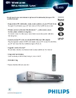
SL400I/05
Brand: Philips Pages: 2
SL400I/19
Brand: Philips Pages: 2

22RH541
Brand: Philips Pages: 33

22RH 545
Brand: Philips Pages: 38

SL400I/00
Brand: Philips Pages: 55

364215376135191
Brand: MonsterLabo Pages: 38

QB-35US3R+AES
Brand: Fantec Pages: 2

MR-35VU3R
Brand: Fantec Pages: 2

ENNHD-1GS
Brand: Encore Pages: 1

ENNHD-1000
Brand: Encore Pages: 1

HD:Book
Brand: 1life Pages: 18

RTX Secure 222-3QR
Brand: CRU Pages: 9

MAC501
Brand: CHIEF Pages: 8


