Pacific 110ACX, Operation Manual
The Pacific 110ACX Operation Manual is essential for understanding how to use your product effectively. Download this manual for free from manualshive.com to access detailed instructions and troubleshooting tips. Enhance your user experience and get the most out of your Pacific 110ACX with this comprehensive manual.
Share
Download


Reviews:
No comments
Related manuals for 110ACX

SCS200
Brand: E-T-A Pages: 48

Liebert MPX Elementary
Brand: Emerson Pages: 16
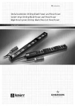
Di-Strip
Brand: Emerson Pages: 20
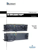
3U MP2-220N POD
Brand: Emerson Pages: 18

Liebert MicroPOD MP2-210K
Brand: Emerson Pages: 16

MPHR2204
Brand: Emerson Pages: 51

Liebert PPC 15-30 kVA
Brand: Emerson Pages: 24

Network Poewr MPH2
Brand: Emerson Pages: 36

Avocent PM 3000
Brand: Emerson Pages: 66

Power View PS570A
Brand: Black Box Pages: 32

ERIFLEX UD400212CU
Brand: Pentair Pages: 2

PDU-6SS
Brand: D&R ELECTRONICS Pages: 12

M7500-PRO
Brand: Panamax Pages: 17

00133757
Brand: Hama Pages: 42

battery protect BP 100
Brand: Victron energy Pages: 15

PDUMV30
Brand: Tripp Lite Pages: 3

PDUMNH20
Brand: Tripp Lite Pages: 4

PDUMH30ATNET
Brand: Tripp Lite Pages: 4


