Industrial Device Server
User’s Manual
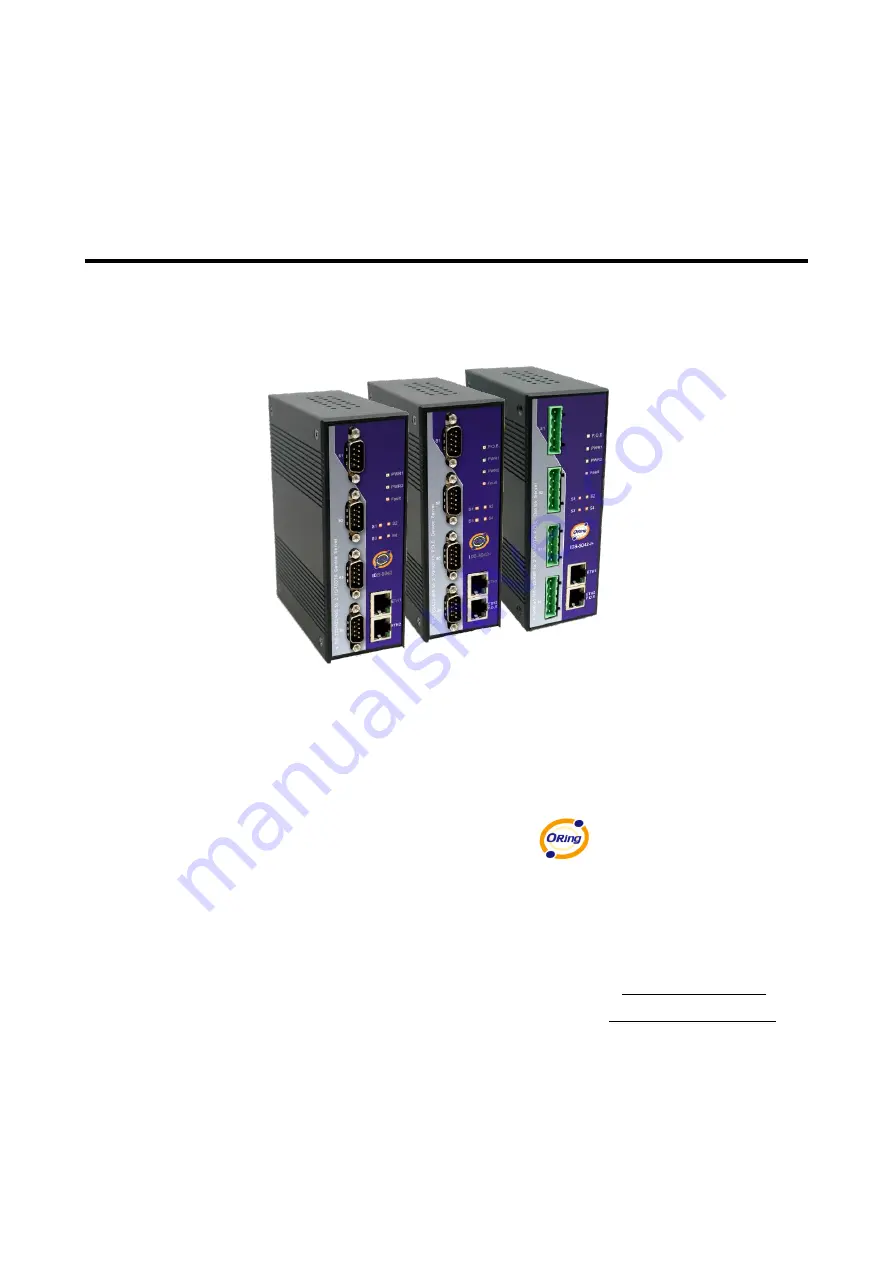
IDS-5042 Series
Version 1.00
Aug 2010.
ORing Industrial Networking Corp.
4F., NO.3, Lane235, Baociao Rd.Sindian City,
Taipei County 23145 Taiwan, R.O.C.
Tel:
+ 886 2 2918 3036
Fax: + 886 2 2918 3084
Website :
E-mail : [email protected]