DATA LOG + / DATA LOG 2+
DIGITAL TIME SWITCH
INSTRUCTIONS FOR USE
DATA LOG + / DATA LOG 2 + is a digital time switch designed for controlling any
electrical installation. It includes the possibility of carrying out short-duration or
pulsed operations (from 1 to 59 seconds), On and Off at a set time, repetitive
cycles (from 1 minute to 99 hours, 59 minutes), automatic summer/winter time
change, holiday (day/month) period, adjustable screen brightness and updating
from an infrared remote control. All these features can be applied to channel C1,
and to C2 if DATA LOG 2+ is used.
Function menus can appear in several languages and they display a chronogram
on screen that shows the programming for the current day.
To view the chronogram, as well as the other unit configurations, it is only
necessary to repeatedly press the
key (info) until the desired display is
obtained.
DATA LOG + has one independent voltage-free switched circuit that allows the
programming of up to 70 operations.
DATA LOG 2+ has 2 independent voltage-free switched circuits that allow the
programming of up to 70 operations between channel 1 and/or channel 2.
INSTALLATION
WARNING: installation and mounting of electric apparatus shall be carried out by
an authorised installer.
ALL POWER MUST BE REMOVED BEFORE PROCEEDING WITH THE INSTALLATION,.
The unit is internally protected from interference by a safety circuit. However,
certain particularly strong fields can alter its operation. Interference can be avoided
if the following installation rules are followed:
- The unit should not be installed next to inductive loads (motors, transformers and
contactors etc.)
- It is recommended to provide a separate line for the supply (if necessary,
equipped with a mains filter).
- Inductive loads must be fitted with interference suppressors (varistor, RC filter).
If the time switch is used in combination with other units at an installation, it is
necessary to check that the assembly so formed does not generate parasitic
interference.
THE POWER SHALL ONLY BE RESTORED WHEN THE EQUIPMENT IS COMPLETELY
INSTALLED.
MOUNTING
Electronic control device for independent installation in distribution cabinet fitted
with symmetrical 35 mm profile in accordance with the standard EN 60715 (DIN
Rail EN 60715 (Rail DIN).
CONNECTION
Connect the mains supply according to the following schematic:
The Line and Neutral position must be respected, checking the connections made.
A wrong connection can destroy the unit.
PUTTING IN SERVICE
For the device to be able to execute control over the installation, IT MUST BE
POWERED UP.
The display will light up and the MAIN screen will appear.
When the equipment is switched off, the screen will also be off, but the date, time
and all programming will be maintained during the four-year lifetime of the
incorporated lithium battery.
In this case, if any key is pressed, the display will temporarily switch on to allow
programming. If no keys are pressed during fifteen seconds, the display will be
switched off again.
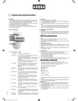
These units have an LCD panel and four keys for adjustment and programming.
The following information is shown on the LCD:
•
Day of the week in text line 1 in the ON state
•
Complete time and date
•
Symbol
= Vacation state
•
Chronogram with the operations for that day
•
State of circuits C1 / C2: ON
, OFF
•
INFO symbol
•
PERMANENT
text in line 2 (if activated)
•
OFF
text in line 1 (if in switched-off state)
•
LOG technology: two text lines for programming help menus
•
Two lines of text in programming help menu style and a chronogram with
48 divisions in which each segment represents thirty minutes
CONFIGURATION
DATA LOG +/ DATA LOG 2+ units leave the factory configured with the current
date and time, and configured as follows:
Hour Mode:
24 h
W-S Change
Automatic (last Sunday of March)
S-W Change
Automatic (last Sunday of October)
Vacations: NO
(deactivated)
Programs:
None (memory empty)
PROGRAMMING
The programming is based on menus and submenus through which we can move
to program operations or make adjustments to the unit. Access to the main menu
from the idle screen is by pressing key
√
. Use the
▼
and
▲
keys to step through
the different menus, which can be entered by pressing key
√
. To go back to the
previous menu, press key
C
.
The data to be entered always appear flashing on the screen.
The structure of the menus is the following:
MAIN MENU
•
PROGRAMS.
This is the menu where the different operations are programmed.
There are 70 memory slots (from PROG_01 to PROG_70).
o
ENTER.
Where we will edit the different programs. With the
▼
and
▲
keys,
we can step from PROG_01 to PROG_70. After selecting one, it is entered
by pressing
√
. Once inside the program, we have the following options:
-
EDIT. The message “PROG_01: EDIT” is shown on screen. By
validating with
√
TYPE C1: ON appears on screen. The type of
operation for the DATA LOG is selected with the
▼
and
▲
keys: C1:
ON, C1: OFF, C1: PULSE, C1: CYCLE. In the case of DATA LOG 2+,
we also have C2: ON, C2: OFF, C2: PULSE, C2: CYCLE. The choice
made is validated with key
√
. Next the hour, minute and combination of
days of the week are chosen for the operation.
In the case of PULSES, it will be necessary to specify the pulse
duration in seconds.
In the case of CYCLES, it is necessary to specify when the cycle will
begin (hour, minute and day of the week); and then, when the cycle
finishes (hour, minute and day of the week). To end the CYCLE
definition, it would only remain to indicate the ON period and the OFF
period respectively (in hours and minutes).
-
COPY. It copies the operation of a program for use in another.
-
PASTE. It pastes the previously copied operation.
-
ERASE. It deletes the selected program.
o
ERASE.
It allows a deletion to be carried out of all the operations in the
programs in one step.
•
CLOCK.
This will set the equipment time. The variables to be configured are (in
this order): year, month, day, hour and minute. The day of the week is
automatically calculated.
•
PERMANENT.
This is the menu in which we can fix a permanent operation (On
/ Off) of channel C1, and of channel C2 in the case of DATA LOG 2+. With the
▼
and
▲
keys we step through the different options:
C1: YES
Æ
C1: NO
Æ
C2:
YES
Æ
C2: NO.
We validate the case we want with
√
. The equipment will not
follow the operations programming for the selected channel if OPTION YES is
selected.
The contact position can be changed manually.
•
LANGUAGE.
This is the menu where the unit language is set.
•
SETTINGS.
This is the menu in which most of the unit configurations can be
carried out.
o
SEASON.
It establishes the time change mode
Summer - Winter
and
Winter
- Summer
.
-
AUTO. It automatically carries out the time change on the last Sunday of
March and on the last Sunday of October.
-
MANUAL. It allows the day and time to be chosen for carrying out the time
change.
-
DESACT. The time change is not carried out.
DAY OF THE WEEK
CHRONOGRAM
INFO SYMBOL
DATE
CURRENT TIME
HOLIDAY
SYMBOL
INFO SYMBOL
CIRCUIT 2
STATUS
STANDBY STATUS DISPLAY
C1 (INFO) STATUS DISPLAY
CIRCUIT 1
STATUS
3
2
1
6
5
4
N
L
M
~
ON
C1
1 - 2
C2
4 - 5
C1
C2
3
2
1
N
L
M
~
C1
DATA LOG +
DATA LOG 2+
OPEN
CLOSE