Optoma HD33, Service Manual
The Optoma HD33 is an exceptional projector designed for true 3D enthusiast viewing. With its impressive specifications and 1080p resolution, this projector delivers an immersive cinematic experience. Access the user manual free of charge from our website for detailed instructions on maximizing the full potential of this remarkable device.
Share
Download


Reviews:
No comments
Related manuals for HD33

REALIS WUX10 MARK II D
Brand: Canon Pages: 12

Multimedia Projector MP8670
Brand: 3M Pages: 2

FL40 series
Brand: Barco Pages: 2
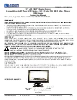
SCR-10IN-LCD-1080P-12V
Brand: Larson Electronics Pages: 2

D13HD2-HS
Brand: Christie Pages: 107

TAB Series
Brand: Kingpin Pages: 4

Table Top
Brand: InFocus Pages: 2

IN5110
Brand: InFocus Pages: 2

FLC200 LED Series
Brand: WE-EF Pages: 9

MP615P
Brand: BenQ Pages: 2

VP1000-W
Brand: Ltc Audio Pages: 32

TDSGABC14
Brand: ERICO Pages: 2

SUPERNOVA 10K
Brand: Vicom Pages: 37

LQMWP
Brand: LinQTab Pages: 23

S1210 Series
Brand: Acer Pages: 56

S5301WM Series
Brand: Acer Pages: 68

X1270 Series
Brand: Acer Pages: 66

X1230S Series
Brand: Acer Pages: 96


