OPTO-EDU A23.0910, Instruction Manual
The OPTO-EDU A23.0910 microscope comes with an easy-to-follow Instruction Manual for seamless setup and operation. You can download the manual for free from our website, ensuring you have all the information needed to make the most of this powerful tool in your research or educational activities.
Share
Download


Reviews:
No comments
Related manuals for A23.0910

CHA
Brand: Olympus Pages: 15

UM08-GN
Brand: ViTiny Pages: 40

SZM Series
Brand: OPTIKA MICROSCOPES Pages: 36

76825
Brand: Levenhuk Pages: 42
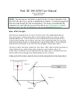
XE-100
Brand: Park Systems Pages: 10

Video Flex® except 2000 series
Brand: Ken A Vision Pages: 1

T-2701
Brand: Ken A Vision Pages: 1

T-1953BP
Brand: Ken A Vision Pages: 2

Vision T-2200C Series
Brand: Ken A Vision Pages: 4

Comprehensive Scope T-1901
Brand: Ken A Vision Pages: 4

T-19541C
Brand: Ken A Vision Pages: 8

T-1941
Brand: Ken A Vision Pages: 8

T-1931C
Brand: Ken A Vision Pages: 8

Digital Comprehensive Scope 2
Brand: Ken A Vision Pages: 8

Comparison Scope T-1924C
Brand: Ken A Vision Pages: 8

Comparison Scope 2 T-19241C
Brand: Ken A Vision Pages: 8

T-22 Series
Brand: Ken A Vision Pages: 12

CoreScope 2 T-17011C
Brand: Ken A Vision Pages: 12


